
Abstract
Immersed boundary-lattice Boltzmann method was used to study the failure of automobile door sealing strip considering fluid-structure interaction under pressure difference. Based on the actual vehicle model, a two-dimensional calculation model of simplified automobile door sealing strip was established by using immersed boundary method, and practical problems such as the equivalent sealing strip wall thickness correction, wall friction, and pressure balance holes were solved. The accuracy of the model was verified by finite element method. The unsteady pressure outside the vehicle was obtained by CFD and verified by wind tunnel experiment, which could be used as references for setting boundary conditions. In the process of studying the seal failure, by setting the average value, the fluctuation amplitude and the frequency of pressure difference, an automatic iterative program was compiled to obtain the failure situations of the seal under critical pressure difference conditions. The results show that the constant value of the unsteady pressure outside vehicle is the dominant factor, then the coupling between the unsteady pressure frequency and the sealing strip natural frequency, or the increase of the fluctuation range will aggravate seal failure.
Keywords
Introduction
When a car drives at a high speed, the pressure on the body surface varies greatly. The pressure difference on both sides not only squeezes sealing strips, but also has an outward aerodynamic effect on the door, resulting in deformation of the door. 1 In this case, the pre-compression of the sealing strip will change and may lead to failure, resulting in a strong leakage noise. 2 During seal failure process, the deformation of the sealing strip and the flow field around it form fluid-structure interaction (FSI),3,4 which makes the study very difficult. In addition, to balance the internal pressure after compression, actual door sealing strips usually have pressure balance holes, 5 which will affect the deformation characteristics of sealing strips and fluid-structure interaction results. In addition, the pressure difference fluctuation caused by the unsteady flow field outside the vehicle will affect the fluid-structure interaction and may exacerbate seal failure, which further increases the simulation difficulty.
Static analysis of mechanical properties and design performance of sealing strips are typically evaluated using nonlinear finite element method (FEM), 6 which can accurately simulate the pre-compression deformation of sealing strips, 6 as well as the deformation and failure under steady pressure difference.7,8 The deformation behavior of the seal under compression, the deformation shape during compression, the contact pressure distribution on the seal and the pressure difference are defined as important performance factors to be considered in the design of door sealing strips. 9 Later, some scholars carried out research on seal leakages, and proposed that the critical leakage pressure mainly depends on the geometric shape and constraint conditions of the seal. 10 In addition to the basic sealing function of automobile seals, it also affects the noise inside vehicles. The decrease in sound insulation performances of sealing strips is directly related to seal failure. 11
However, the actual working conditions of vehicle sealing strips are more complex. The limitation of simulating sealing systems by traditional finite element method is that it cannot accurately simulate the flow and fluid-structure interaction after seal failure, which must be solved by computational fluid dynamics (CFD) method. To solve the FSI problem, Arbitrary Lagrangian Euler (ALE) method and Transformed Space Domain/Stable Space-Time (DSD/SST) method are mainly used.12,13 In these methods, to avoid severe grid distortions, the grids usually need to be regenerated frequently, resulting in a large consumption of computing resources. Whereas immersed boundary-lattice Boltzmann method (IB-LBM) is based on non-conformal Cartesian grids and is therefore more efficient when dealing with complex and moving geometries.
Lattice Boltzmann method (LBM) is derived from gas dynamics theory, and unlike traditional numerical methods, LBM is a particle dynamics-based method that avoids the discretization of Navier-Stokes equations. It has been widely used due to the simplicity of programming and easy parallelism. Based on application research of LBM, it has been successfully applied in the fields of incompressible flow, 14 heat transfer, 15 compressible flow, 16 multiphase flow, 17 suspended particle flow, 18 etc. The mechanism of many complex phenomena has promoted the development of related disciplines.
Immersed boundary method (IBM), first proposed by Peskin, 19 provides a simple method to solve complex fluid-structure boundaries and large deformations. 20 IBM uses Eulerian description of fluids and Lagrangian description of fluid-structure interfaces, without the need to generate complex body-fitting meshes according to the shape of object, which is widely used in fluid-structure interaction problems.
On this basis, a new FSI simulation techniques called immersed boundary-lattice Boltzmann method (IB-LBM) have developed rapidly in recent years.21,22 it has been developed to model fluid-structure interactions, including deformable particles, 23 elastic filaments, 24 flexible sheets 25 and flexible beams, 26 etc. The door sealing strip involved in this paper is a uniform thin-walled structure, and it has great advantages to use IB-LBM to simulate.
This paper uses IB-LBM to study the seal failure of fluid-structure interaction under dynamic pressure difference conditions. In previous modeling studies (citing our previous paper 27 ), an attempt has been made by using IB-LBM to simulate fluid-structure interaction of sealing strip, which solved a series of mathematics problems such as hyperelastic material mathematics, pre-compression, friction, etc. Based on the above research, this paper further refined the physical properties of uniform thin-walled sealing strips of actual vehicle doors, and solved practical modeling problems such as the thickness correction and pressure balance holes. The accuracy of the IB model was verified by finite element method. After the modeling is completed, the failure simulation of typical working conditions of the sealing strip under different dynamic pressure differences was carried out, and the specific relationships among the failure of the sealing strip, the dynamic pressure difference and the natural modal frequency of the sealing strip was studied.
Basic theory and mathematical derivation
Lattice Boltzmann method
This paper uses Multiple Relaxation Time (MRT) lattice Boltzmann model. 28 Compared with Single Relaxation Time (SRT) model, 29 MRT model has better computational stability. The governing equation is
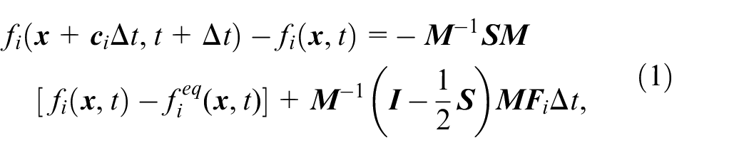
where the subscript
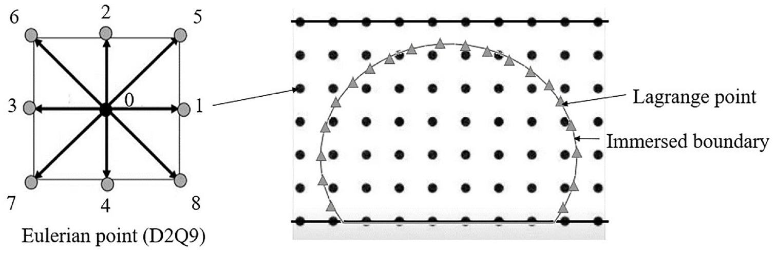
Immersed boundary and D2Q9 model in LBM.
Hyperelastic material mechanics model
The commonly used material for door seals is Ethylene Propylene Diene Monomer (EPDM). This kind of hyperelastic material can be represented by Rivlin nonlinear model based on measurements. In this paper, it is assumed that the sealing strip is incompressible, so the Mooney-Rivlin model of incompressible hyperelastic material is obtained as follows, 30 and its second-order expression is

where
According to previous research, 27 the internal forces of the sealing strip include, normal stress,
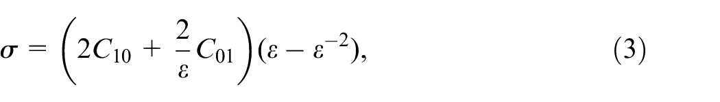
shear stress,

Among them,

where
Immersed boundary method
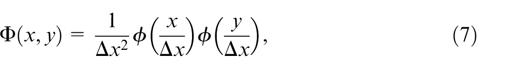
In this paper, IBM is used to simulate fluid-structure interaction between sealing strip and air. In immersed boundary method, the fluid is described by Euler grid, and the solid boundary is described by Lagrangian grid, as shown in Figure 1. The fluid lattice nodes have fixed positions
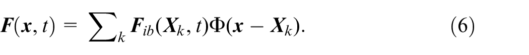
In this paper,
Modeling of the door sealing system
Computational domain and boundary conditions
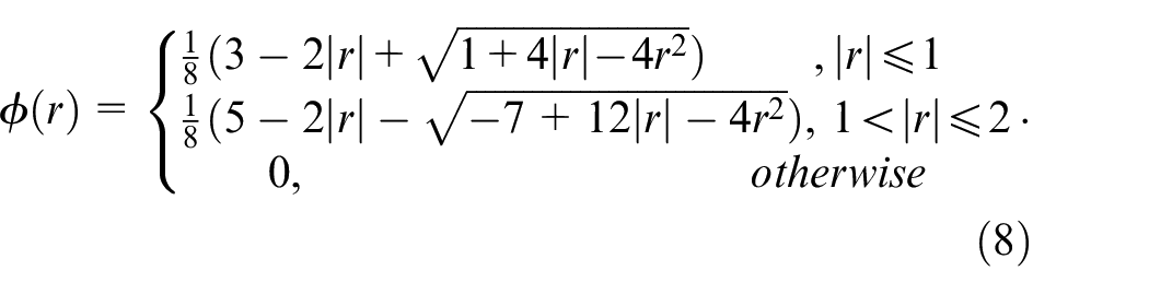
The IB-LBM computational domain is shown in Figure 2. The height
IB-LBM model.
The top and bottom boundaries were set as no-slip boundaries representing sheet metal. The left and right boundaries were set as non-equilibrium extrapolation scheme pressure inlet and outlet boundary, 32 so that the pressure difference can be adjusted by setting their pressure values. Considering the actual working conditions of door sealing strips, the pressure fluctuation usually occurs on the low pressure side outside the vehicle, so set the pressure inlet to a stable high pressure and the pressure outlet to a fluctuating low pressure. Considering that the instantaneous pressure loading has a large impact on the flow field and may cause a large instantaneous deformation of the sealing strip, the pressure was selected to be loaded in the form of a sine function. After the steady pressure was loaded, the dynamic pressure was superimposed on it.
Thickness correction
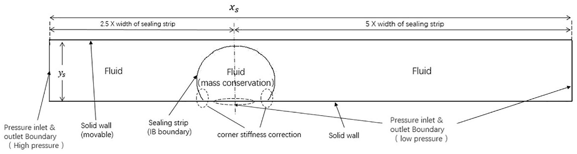
Since the IB model simplifies the evenly thick sealing strip into a single-layer immersed boundary, to match the properties of the sealing strip in the IB model with the properties of the actual sealing strip. Abaqus software was used to model the sealing strip, and static deformation analysis was carried out on the sealing strip of different thicknesses. As shown in the Figure 3, the sealing strip thickness is
The finite element static model of the sealing strip.
Under different sealing strip thicknesses, by adjusting the force F of the sealing strip, the cubic ratio of the force under the maximum deformation of 1 mm of the sealing strip and sealing strip thickness is approximately constant, that is, the equivalent stiffness of IB and the sealing strip thickness are cubic relationship, as shown in Figure 4.
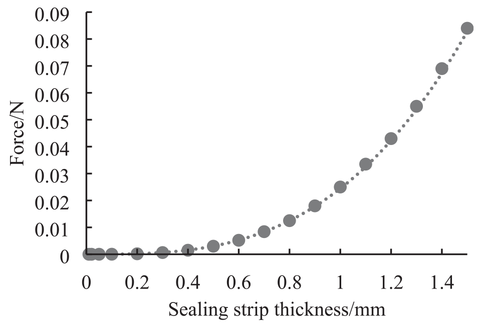
Relationship between the sealing strip thickness and the acting force under the same pre-compression.
To verify the accuracy of the sealing strip being simplified into single-layer IB grids, that is, the sealing strip thickness will not affect its deformation characteristics. Under different sealing strip thicknesses, multiply the force F that will deform the sealing strip by 1 mm maximum by different coefficients n, the maximum deformation under this force is shown in Figure 5. The maximum deformation of the sealing strips with different thicknesses is very close. It can be obtained that the sealing strip thickness has little effect on its deformation characteristics, and can be simulated by single-layer IB grids.
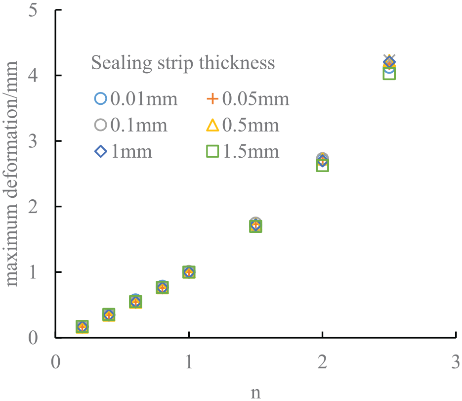
The maximum deformation of the sealing strip after changing the force.
In this paper, the modalities of the sealing strips with different thicknesses under the condition that the bottom is fixed were obtained by simulation. The first four-order vibration modes with greater influence on fluid-structure interaction are mainly selected, as shown in Figure 6. The first mode is that the sealing strip swings left and right in the x direction, the second mode is that the sealing strip is stretched and squeezed up and down along the y direction, the third mode shows a certain torsion trend, and the fourth mode shows the shape of extrusion in the middle while stretching on both sides of the upper side of the sealing strip. The relationship between the first four-order mode frequency and sealing strip thickness is shown in Figure 7. The modal frequencies of the sealing strip are approximately proportional to the thicknesses, which provides a reference for the subsequent selection of dynamic pressure difference.
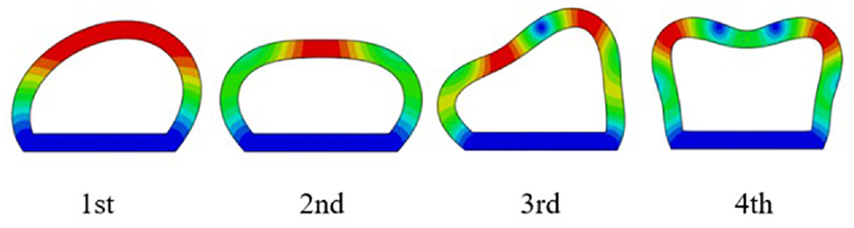
The first four modes of the sealing strip.
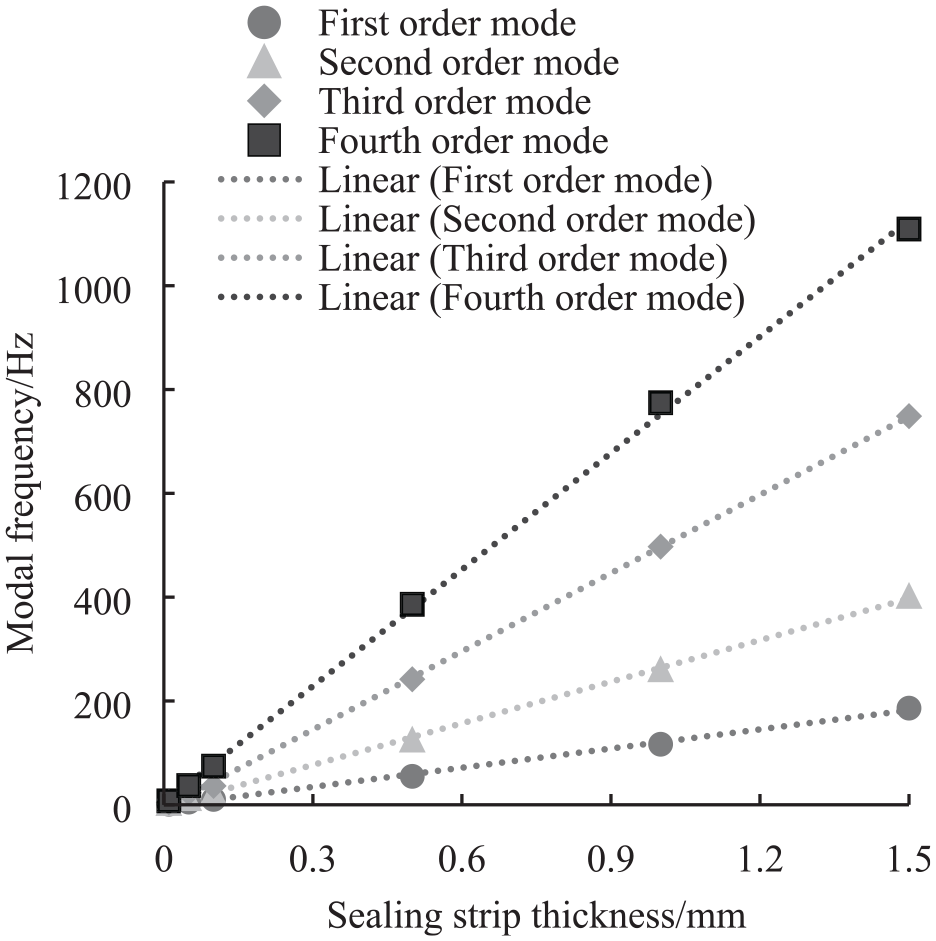
Relationship between the sealing strip thickness and the first four modes.
Pre-compression and friction
Typically, sealing strips are attached to the door and are subject to a certain pre-compression load when the door is closed. At the same time, the part in contact with the door sheet metal will be affected by friction, so the force on the contact position between the sealing strip and the sheet metal needs special treatment, which has been mentioned in our previous study, 27 and the modeling here is consistent with it.
Pressure balance hole
Considering that to balance the internal pressure after compression, actual door sealing strips are usually provided with pressure balance holes, 5 which are connected to the low pressure side outside the vehicle. It can be considered that the pressure inside the sealing strip is consistent with that outside the vehicle.
In order to simulate the pressure balance hole of actual door sealing strips, this paper sets a pressure inlet at the bottom of the sealing strip model, and the inlet pressure is consistent with the low pressure side. The width of the pressure outlet was selected as half of the length of the bottom of the sealing strip, as shown in Figure 2.
In order to verify that the deformation of the sealing strip can be more accurately simulated after applying the pressure balance hole, and the internal pressure can reach a state of equilibrium with the low pressure side, a force F was applied on the top of the sealing strip. The internal and external pressure and the deformation results of the sealing strip with and without the pressure balance hole are compared with the finite element simulation, as shown in Figure 8.
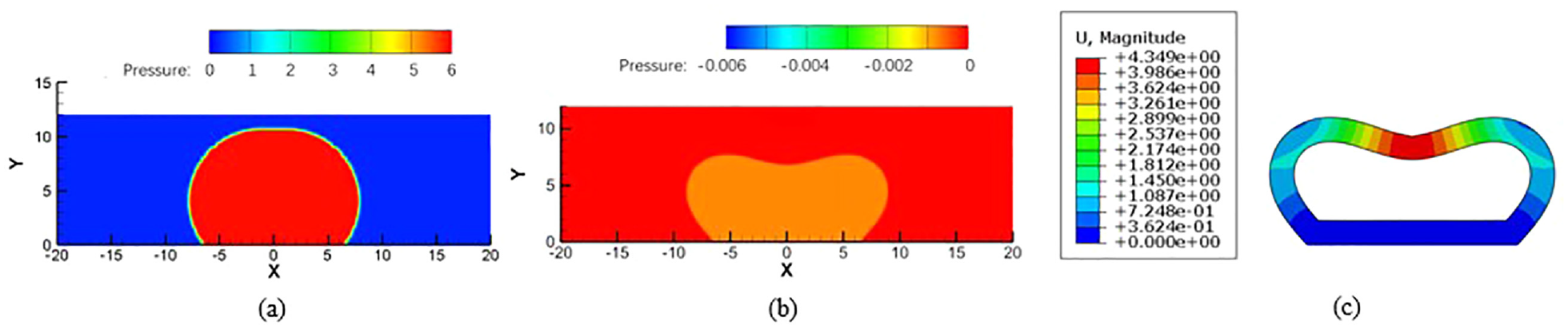
The deformation result of the sealing strip under the vertical downward force F: (a) without pressure balance hole,(b) with pressure balance hole, and (c) finite element deformation result.
When there is no pressure balance hole, the internal pressure of the sealing strip increases significantly after the internal volume of the sealing strip is reduced, and at the same time, due to the influence of the large internal pressure, the deformation of the sealing strip is small. After considering the pressure equalization hole, the pressure difference between inside and outside of the sealing strip is almost the same, and the deformation results are closer to the finite element simulation.
Static deformation verification
According to the above correction method, the immersed boundary was set, the IB sealing strip model was established, and the static deformation of the sealing strip was verified.
The pre-compression process in the pre-compression chapter is verified here. For the judgment of door seal failure, the contact between the sealing strip and the sheet metal is the main judgment condition. Therefore, the x-coordinate of the contact point between the sealing strip and the sheet metal after pre-compression is selected for comparison, as shown in Figure 9. The coordinates obtained by these two methods are very close. Therefore, it can be considered that the material properties of the IB sealing strip can simulate the deformation of the sealing strip accurately.
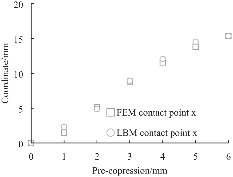
Quantitative verification of deformation of IB sealing strip.
Obtaining pressure difference boundary conditions
Vehicle unsteady simulation
In this paper, the research object of the sealing strip boundary conditions is a sedan, and the corresponding fluid boundary conditions are mainly obtained through simulation. The simulation used a full-scale model, the calculation domain was a cuboid, and its size is 12 times, 6 times, and 6 times the length, width, and height of the car, respectively. Meshing was performed using Hypermesh software, the surface mesh and volume mesh were triangular meshes and tetrahedral meshes, respectively, and the maximum mesh size was 200 mm. The maximum size of key positions such as near the car body was 25 mm, and this grid size met the requirements of grid independence. After the above settings, the total number of grids was about 35 million.
The numerical simulation was performed using Fluent software, and the velocity conditions included 80, 100, 120, 140, and 160 km/h. The turbulence model of the Reynolds time-averaged k-epsilon method was selected for the steady-state calculation, and the calculation accuracy was second-order accuracy, with a total of 10,000 iterations. Based on the steady state results, the unsteady flow field was calculated. The analysis frequency band was selected as 20–2500 Hz, so the time step of transient calculation was 0.0002 s. In the process of calculation, according to the change trend of parameters such as residual error and pressure, it is considered that the flow field parameter region was stable after 0.5 s. Therefore, in this unsteady calculation, the data within 0.5–1 s was collected and analyzed.
Usually, the negative pressure of the front door is significantly larger than that of the rear door, and the follow-up focus on the front door for analysis. The absolute value of the pressure inside the vehicle is usually small, while the pressure outside the vehicle fluctuates relatively greatly, so here the pressure difference between the inside and outside of the vehicle is set as the external pressure of the vehicle. Nineteen monitoring points are arranged on the sealing strip of the front side door, as shown in Figure 10.
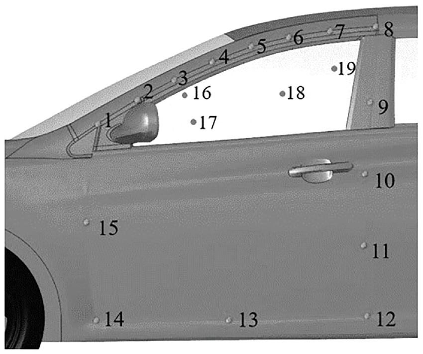
Pressure monitoring point at door sealing strip.
Wind tunnel test
To verify the reliability of the surface pressure data obtained from the vehicle simulation, the internal and external pressures of the vehicle were measured through the vehicle wind tunnel test. The test was completed in the vehicle aeroacoustics wind tunnel of Tongji University-Shanghai Automobile Wind Tunnel Center. 33 The test conditions included wind speeds of 80, 100, 120, 140, and 160 km/h, which corresponded to the above simulations.
This paper focuses on the unsteady pressure at the door seal. The unsteady pressure measurement used the GRAS 40PS-1 CCP surface microphone to measure the time-domain signal of the surface pressure at the key measuring points on the surface of the front side window. As shown in Figure 11, it was collected by the Head Acoustics SQLAB III multi-channel sampling system for 10 s signal with a sampling frequency of 48 kHz.
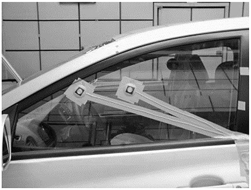
Unsteady pressure test measuring point.
Because measuring point 16 is close to the door frame, it has more reference value for the unsteady pressure difference between the inside and outside of the vehicle. At the same time, the working condition of the sealing strip is the worst at the speed of 160 km/h. Therefore, the frequency spectrum of the pressure pulsation level of measuring point 16 on the side window obtained by the wind tunnel test and CFD simulation at the vehicle speed is selected, as shown in Figure 12. The variation trend and order of magnitude of the simulation and test results are basically the same, and the pressure pulsation level decreases gradually with the increase of frequency in the entire analysis frequency band. From this, it is known that the unsteady calculation of the vehicle flow field has certain reliability.
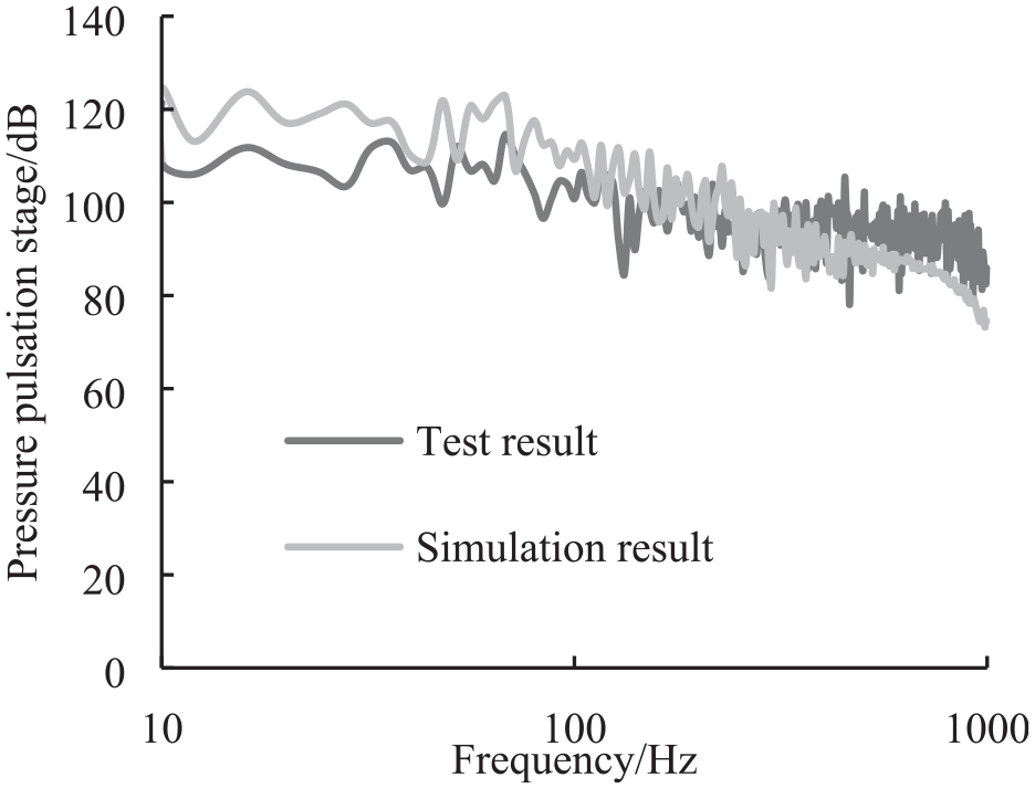
Pressure pulsation level spectrum of measuring point 16.
Unsteady pressure difference results
Under the speed of 160 km/h, the pressure difference between the inside and outside of each measuring point of the vehicle is shown in Figure 13. The pressure difference inside and outside the vehicle is mostly negative (the pressure inside the vehicle is larger than outside). The pressure difference near the upper edge of the window frame is large, while the pressure difference at the bottom of the door and the rear side is relatively small. Specifically, the average absolute value of the pressure difference at measuring point 3 is the largest, reaching −1000 Pa; the measuring point 2 has the largest fluctuation range of the pressure difference, while the minimum value is the smallest, reaching −2600 Pa.
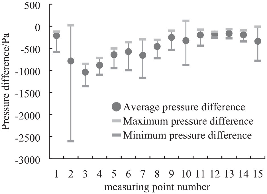
Pressure difference of monitoring points under 160 km/h.
From this, it can be concluded that the working conditions of measuring point 2 and measuring point 3 are relatively poor. Taking the pressure difference characteristics of these two working conditions as a reference to set subsequent boundary conditions.
Seal failure analysis
Seal failure judgment conditions
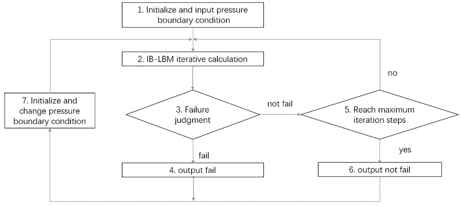
To quickly and conveniently judge whether the sealing strip fails under various specific pressure difference conditions, the program logic for judging seal failure is designed in this paper, as shown in Figure 14. In each step of the calculation of the flow field, a judgment step for seal failure is added.
Logic of seal failure judgment.
The judgment conditions are as follows:
Initialize and enter pressure difference conditions.
Perform IB-LBM flow field calculation iterations.
Judging at each iteration step, if the maximum point of the ordinate
Output the failure result under this pressure difference condition, and go to step 7.
Considering that no seal failure to seal failure is a dynamic process, to avoid misjudgment, a second judgment needs to be added. If it is guaranteed to reach a certain number of iteration steps, it is judged as no failure, then go to step. Otherwise, go back to step 2, enter the next iteration.
Output the result of no failure under this pressure difference condition, and go to step 7.
From this, the result of whether the sealing strip fails under this working condition is obtained. After outputting, the flow field conditions are initialized, and the pressure difference condition is updated. Return to step 2 to perform the calculation of the next working condition.
Static pressure difference condition
A two-dimensional cross-sectional model according to the size of the real vehicle sealing strip was established by using Abaqus software, as shown in Figure 15. The actual door seal is squeezed by the door to generate a certain pre-compression. To simulate this condition, the downward displacement of the door sheet metal was applied as the pre-compression δ of the seal. Generally, the door seal only fails when the pre-compression is very small, here, the pre-compression was taken as 1 mm, fixed constraints were imposed on the body sheet metal and the bottom of the sealing strip, and a pressure load was applied on the left side of the sealing strip to simulate the internal and external pressure difference. The friction coefficient between the sheet metal and the sealing strip was taken as 0.3, the deformation of the door and body sheet metal can be ignored, and they were all set as rigid bodies, and the boundary conditions are shown in Figure 15.
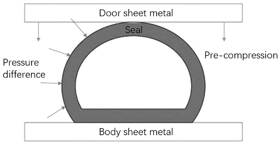
Quasi-static pressure difference boundary condition of finite element sealing strip.
According to the simulation results of the unsteady pressure difference outside the vehicle, the pressure difference is taken as 1000 Pa. According to the finite element simulation results, seal failure will not occur under larger thickness and pre-compression of the sealing strip. To reach the critical state of failure, after debugging, the sealing strip thickness was 0.8 mm and the pre-compression was 1 mm. The pressure load on left side of the sealing strip was set to 1000 Pa, and the simulation results shows that the sealing strip loses contact with the sheet metal, and a failure occurs.
The accuracy of IB static deformation has been verified in Section 3.6. Next, IB-LBM was used to solve the simulation flow field results of the pressure difference between the left and right sides of the sealing strip verify whether the seal failure can be accurately judged.
The deformation results of the sealing strip at 900 and 1000 Pa are shown in Figure 16. The sealing strip is still in contact with the wall under 900 Pa, which isolates both sides of the sealing strip. There is no airflow exchange between the left and right sides of the sealing strip, and the seal does not fail. At 1000 Pa, the upper part of the sealing strip loses contact with the wall surface, then air starts to flow at the formed slit and failure occurs. The failure pressure difference is also consistent with the finite element simulation.
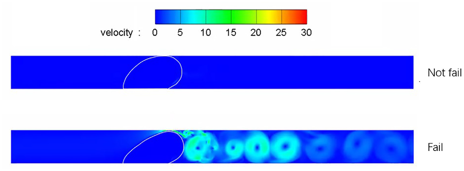
IB-LBM seal failure results and flow fields.
Typical dynamic pressure difference conditions
To obtain the influence of various parameters of different forms of pressure difference on seal failure, it was set as

Among them, A is the average pressure difference (effective pressure difference), B is the pressure difference fluctuation range, and
Steady pressure
When B = 0, that is, the pressure difference is constant, the relationship between seal failure and pressure difference is obtained as shown in Figure 17. The failure pressure difference is about 1000 Pa. When the pressure difference is lower than 950 Pa, the seal failure phenomenon will not occur. When the pressure difference is higher than 1000 Pa, the seal failure phenomenon will occur, and the number of failure steps generally shows a downward trend, indicating that the greater the pressure difference, the failure. The faster the speed is, and the critical failure pressure difference obtained by LBM is consistent with the finite element results, which also verifies the accuracy and applicability of LBM in simulating the seal failure problem.
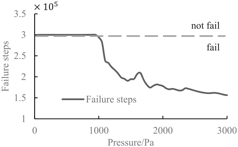
Seal failure results under steady pressure difference.
Different frequencies
Set the average pressure difference A to 1040 Pa, B = A/10, change the pressure difference fluctuation frequency
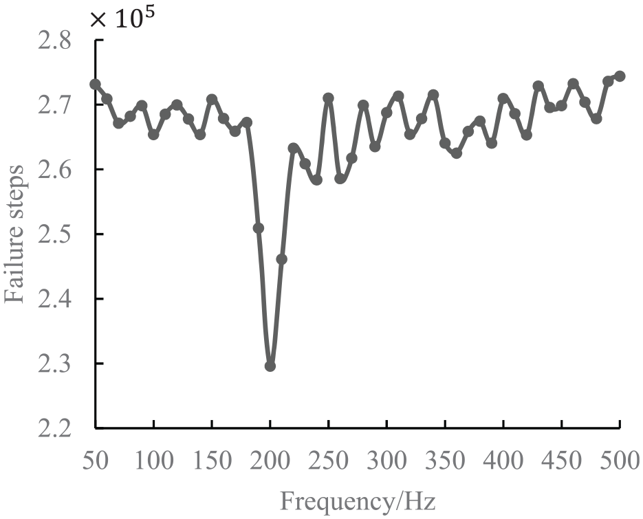
Failure steps under different pressure fluctuation frequencies.
Different pulsation amplitudes (uncoupling frequency)
To obtain the influence of the pressure difference fluctuation amplitude on the seal failure, the pressure difference fluctuation frequency
The results obtained are shown in Figure 19, and it will fail under different pressure fluctuation amplitudes under the pressure difference of 1000 Pa. At 960 and 980 Pa, the sealing strip will not fail when B/A = 0, that is, under the constant pressure difference, and gradually increase the pressure fluctuation range. At 960 Pa, the sealing strip fails at B/A = 1.5; at 980 Pa, the sealing strip fails at B/A = 0.6. And continue to increase B/A, the number of seal failure steps is shorter, the seal failure is faster, and the number of failure steps shows a step-like decrease.
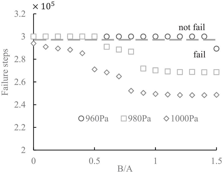
Seal failure results under different pressure fluctuations.
Different pulsation amplitudes (coupling frequency)
Compare the failure of the sealing strip when the unsteady pressure difference fluctuation frequency is 200 and 100 Hz, that is, the coupling frequency and the non-coupling frequency, the average pressure difference is 980 Pa, and the pressure difference fluctuation amplitude B gradually increases from 0.1 to 1.5 A, as shown in Figure 20.
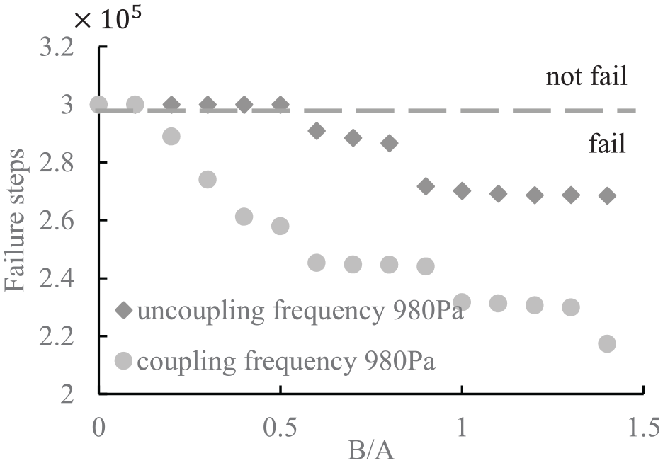
Seal failure results under different pressure fluctuation frequencies.
Under the same pressure fluctuation amplitude and coupling frequency, the seal failure situation is significantly aggravated compared with the non-coupling frequency, the fluctuation amplitude of the critical pressure difference for seal failure is smaller, and the number of failure steps is also less.
Conclusion
In this paper, a two-dimensional fluid-structure interaction simulation of the sealing system was carried out by IB-LBM, and the mathematical modeling of the force transfer between the fluid and the solid on both sides was established. In addition, it also solved the problems caused by actual engineering phenomena such as the setting of hyperelastic material properties of sealing strip, the friction between metal surface and sealing strip, and the inner pressure balance of the sealing strip. The static deformation and failure of the IB-LBM model were verified with the finite element method, indicating that the model has high accuracy.
After modeling, the seal failure judgment logic was established, and the pressure difference between inside and outside of the vehicle was obtained by CFD and wind tunnel tests. Through analysis of pressure difference conditions with small pre-compression and subcritical failure of the sealing strip, the following conclusions are obtained:
When effective pressure difference only contains steady part, its magnitude is the decisive factor for failure of the sealing strip, and the greater the pressure difference, the faster the sealing strip will fail.
When the pressure difference contains periodic pulsation, the pulsation frequency is the key factor affecting the seal failure. If it is close to the vertical modal frequency of the sealing strip, that is, when the fluid is coupled with the solid, the seal failure is significantly exacerbated. When the frequency difference between them is large, the influence of unsteady pulsation can be almost ignored.
When the fluid and solid are in the coupling frequency state, the increase of pressure fluctuation will aggravate the seal failure.
Footnotes
Declaration of conflicting interests
The author(s) declared no potential conflicts of interest with respect to the research, authorship, and/or publication of this article.
Funding
The author(s) received no financial support for the research, authorship, and/or publication of this article.