
Abstract
An advanced ignition technique is developed to achieve multi-event breakdown and multi-site ignition using a single coil for ignition quality improvements. The igniter enables a unique elastic breakdown process embracing a series of high-frequency discharge events at the spark gap. The equivalent electric circuits and current/voltage equations are identified and verified for the first time to explain the working principle that governs such an elastic breakdown process. Benchmarking tests are first performed to compare the elastic breakdown ignition with the conventional and advanced multi-electrode ignition systems. The elastic breakdown and spark events are thereafter analyzed through current and voltage measurements and high-speed imaging techniques. Finally, ignition tests in combustion chambers are performed to examine the effects on the ignition process in comparison with conventional coil-based ignition systems. The experiments show that, the elastic breakdown ignition can distribute multiple high-frequency breakdown events at all electrode pairs of a multi-electrode sparkplug while using only one ignition coil, thereby offering significant cost saving advantage and packaging practicability.
Keywords
Introduction
Ignition devices are widely used in propulsion applications primarily automotive gasoline engines. An ignition system serves the key purpose of providing a reliable ignition source at a desired timing, and it needs to guarantee reliable functionality over the entire engine operating range, in both steady-state and transient operations, and under all climatic and geographic conditions. An ignition failure can result in poor engine performance, high pollutant emissions, faulty powertrain maneuvers, and sometimes catastrophic hardware damages. 1 Therefore, the research and development of ignition systems traditionally focus on hardware robustness and at low cost throughout the service life. 2
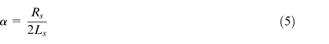
In recent decades, ignition products have evolved to offer continuous improvements in control precision and flexibility to address fuel economy and emission requirements. The ignition hardware design has advanced from mechanically timed ignition, for example, the break-point ignition, to electronic ignition control dedicated for each cylinder, for example, coil-on-plug ignition. 3 Despite the incremental hardware upgrades, the fundamental mechanism of coil-based inductive ignition remains the same, and these coil-based ignition systems dominate the mainstream markets of spark ignition engines.4,5
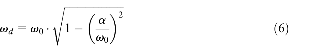
With regard to successful ignition, it is essential to secure flame kernel formation and sustain flame front propagation in an ignition event. 6 As demonstrated by the authors previous studies and investigations from other researchers, ignition quality depends on many impacting factors, including but not limited to the ignition energy, electrode contamination, gap distance, gas flow, and mixture properties such as the air-fuel ratio, density, temperature, and the molecular structures.7–9 The conventional ignition systems have been performing well for stoichiometric burn, naturally aspirated, and/or turbocharged gasoline engines. However, recent technologies enabling engine downsizing and diluted combustion aim to improve fuel efficiencies but inevitably alter the in-cylinder thermodynamic conditions beyond current boundaries, which poses substantial challenges on the ignition systems.10,11
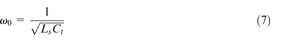
Downsizing demands a higher power density to deliver desired engine performance while meeting low load and idle quality requirements at the same time. The ignition system, therefore, faces a dilemma of sufficing both ends of a widened engine load range and the resultant greater span of cylinder pressure and temperature. For example, a common practice is to reduce the spark gap to ease the spark breakdown for a highly boosted engine at full load, but the ignitability at engine idle becomes a potential problem.
In the other aspect, the charge dilution naturally lowers the inflammation propensity when exhaust gas recirculation (EGR) and/or lean burn are applied. In a homogeneous mixture, the reduced ignitability near the spark poses challenges to reliable flame kernel formation and flame-front propagation development. 12 In a stratified mixture, the injection strategy intends to create conditions in the spark gap favorable for ignition; however, the mixture properties exhibit fluctuations near the spark in both spatial and temporal domains, especially when strong charge motion is introduced to accelerate the burning of diluted combustion.13,14 As a result, conventional ignition systems face demanding requirements for delivering successful spark events, due to the lack of desired discharge duration and/or sufficient spark area/volume.
Active research programs around the world target to develop advanced ignition technologies to tackle the abovementioned challenges. When the spark energy is deposited through a single spark discharge channel, such as using a conventional ignition system, the research approach primarily relies on enhancement of the ignition energy15,16 and the breakdown power. 17 At the same time, novel research has been conducted to extend the ignition duration and/or increase the number of ignition events via advanced techniques such as continuous discharge.18,19
Other innovative ignition technologies also aim to produce ignition at multiple sites or in a larger volume to accommodate the spatial inhomogeneity of the air-fuel mixture. The multi-site and volumetric ignition technologies have been demonstrated to effectively improve the combustion stability of a diluted cylinder charge.20,21 For instance, research results have shown that corona ignition generates an array of plasma steamers to reach a large volume in the combustion chamber. 22 Discharge along the ceramic surface is applied to form multiple ignition sites for racing applications. 23 Double-spark ignition systems utilize a bridging electrode to form more than one plasma channels, thereby extending the overall arc length in a spark event.24,25 Upon a spark command, electrode bridging allows multiple spark arcs distributed in the spatial domain, that is, between electrodes, but it cannot enable more than one breakdown events in the electrode gap.
Another innovative method patented by the authors’ group integrates multiple pairs of electrodes within a single sparkplug to enable multiple spark channels simultaneously. 26 As shown in Figure 1, spark events of a multi-core igniter are compared with a production sparkplug during spark discharge. The multi-core igniter generates three spark channels in different directions and locations, which substantially increases the probability of successful ignition as the air-fuel mixture flows across the spark gaps. The multi-core igniter has been studied in a single cylinder research engine to extend the lean-burn and EGR diluted combustion limits, 27 as well as demonstrated in a production engine to improve fuel economy. 28
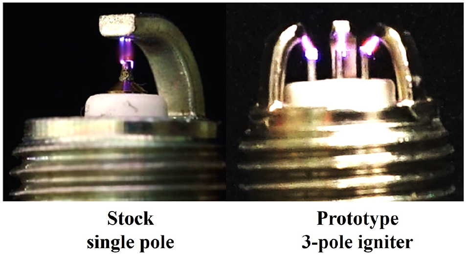
Spark event comparison between a production sparkplug and a multi-core igniter.
Conventionally, a coil-based ignition system employs one set of ignition coil to generate one spark event upon receiving the spark trigger. Achieving multiple breakdown events generally requires a fast-charging coil and high-frequency spark triggers to repeat the processes of primary coil charging and secondary coil discharging within a short time window.29,30 In other cases, multiple coils are needed along with staggered spark triggers to sustain one prolonged discharge process.31,32 Similarly, the multi-core igniter requires a matching number of coils to drive multiple cores. It is desired to produce multiple breakdown events using only one ignition coil upon one spark trigger, which offers system simplification and cost reduction. Therefore, this research targets to demonstrate an innovative ignition mechanism to generate multiple breakdown events with one ignition coil triggered by a single spark command, and reveal the working principle in great detail to understand the elastic breakdown concept as patented by Zheng and Yu. 33 In addition, the authors intend to combine such an innovative ignition mechanism with the multi-core ignition system to deliver spatially distributed sparks and, at the same time, sequentially generate multiple spark events at each spark gap using only one ignition coil, as shown in Figure 2.
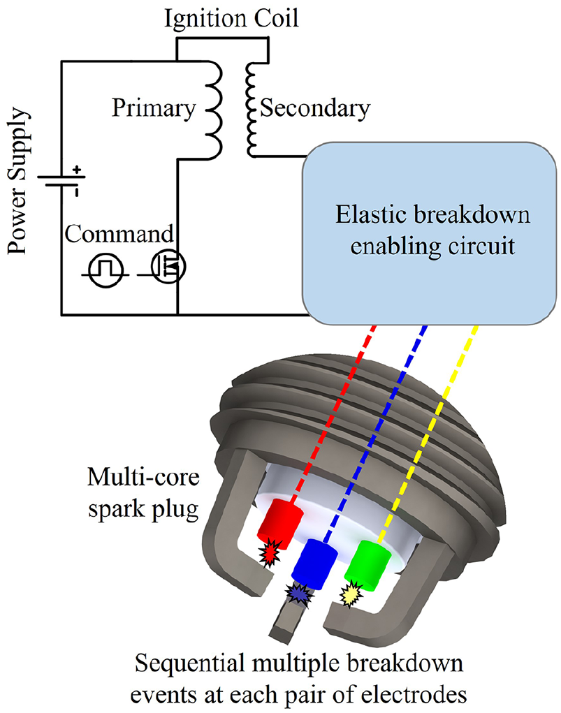
Schematic of multiple breakdown events at electrode pairs of a multi-core sparkplug.
Experimental setup
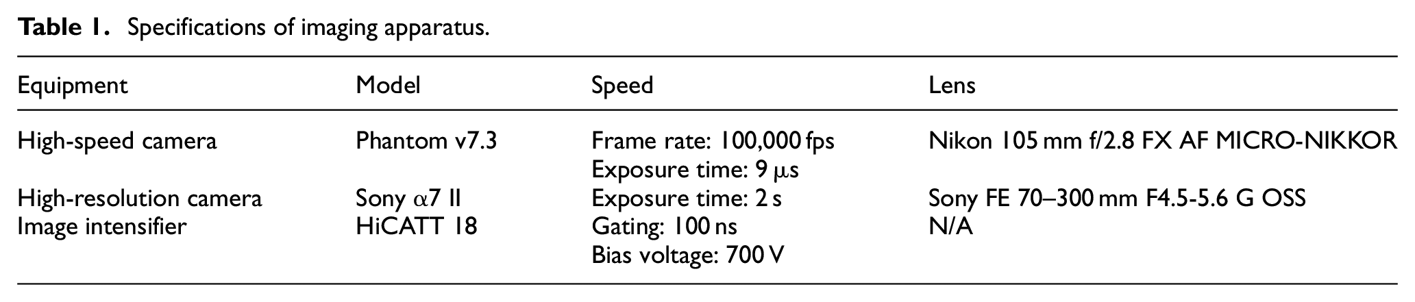
The advanced ignition research platform employs optical combustion vessels and high-speed imaging techniques to visualize the spark ignition and subsequent burning processes. As illustrated in Figure 3, the testbed comprises the high-precision control system, advanced ignition hardware, an optical combustion vessel equipped with gas exchange devices, and a high-speed camera and an image intensifier to capture direct images of the spark events. The ignition experiments use Schlieren imaging to visualize ignition and flame propagation. The specifications of the high-speed imaging equipment are given in Table 1.
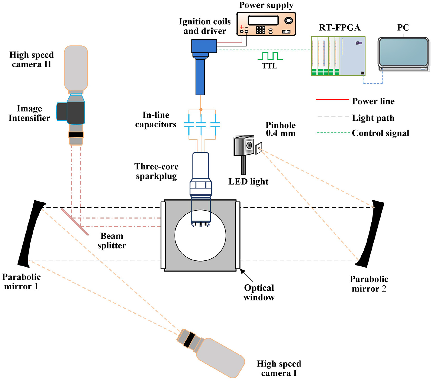
Ignition research platform with high-speed imaging capabilities.
Specifications of imaging apparatus.
A modular adapter at the top of the combustion vessel allows testing different sparkplug designs, including the multi-core igniter patented by the authors’ group. 20 In previous studies, 22 the multi-core igniter has demonstrated advantages of improving engine fuel efficiency operating under diluted gasoline combustion; each pole of the igniter generates one spark event per combustion cycle and in total 24 ignition coils are used for an eight-cylinder engine. Details of the multi-core igniter are documented in Hampe et al. 20 and Burrows et al. 22 This research, in contrast, deploys only one ignition coil along with separate in-line capacitors in the electrical circuits leading to individual electrodes.
The coil charging process is managed though an insulated gate bipolar transistor (IGBT) along with the control system encompassing a real time (RT) controller with a field programmable gate array (FPGA) module. The RT-FPGA system provides desired speed and precision of the ignition command and offers controllability of varying charging durations and charging strategies. The selected IGBT V3040p has a turn-off slope of approximately 4.8 µs and serves as the ignition coil driver in the research setup. Upon receiving the ignition signal from the RT-FPGA system, the IGBT actuation generates a transient high voltage in the primary coil. The system therefore enables programmable generation of controlled charging durations and offers flexibility of experimenting unconventional ignition strategies. The control capability of the ignition research platform is essential to generate high-quality data and make fair comparisons when studying different ignition systems and charging strategies, as demonstrated in previous studies.5,14
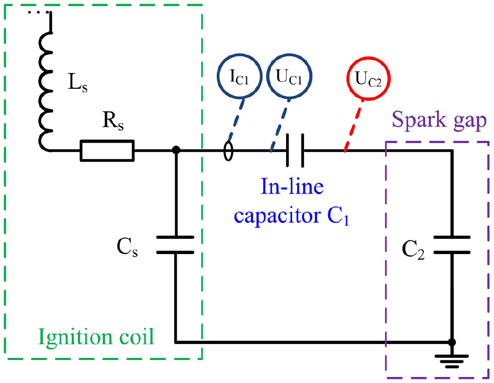
The electrical circuit of an ignition system is re-designed to enable multiple breakdown events upon a single spark trigger. Among other configuration changes, a key enabler is the in-line capacitor integrated between the secondary coil and the spark gap. The electrical circuit of the elastic breakdown ignition is shown in Figure 4. Prior to the breakdown in the spark gap, the secondary coil, the in-line capacitor, and the parasitic capacitor form a series RLC oscillation circuit, similar to that in the conventional ignition system. The unique feature of this circuit design is the altered electric voltage interaction at the ignition coil and at the spark gap when breakdown occurs, which offers the possibility of enabling multiple breakdown events. In order to understand the electrical circuit behavior, the experimental setup includes current and voltage measurements at both upstream and downstream of the in-line capacitor. These electric measurements complement the high-speed imaging techniques to better understand the spark discharge process and its effects on ignition and flame development. The specifications of the electrical measurement devices are listed in Table 2.
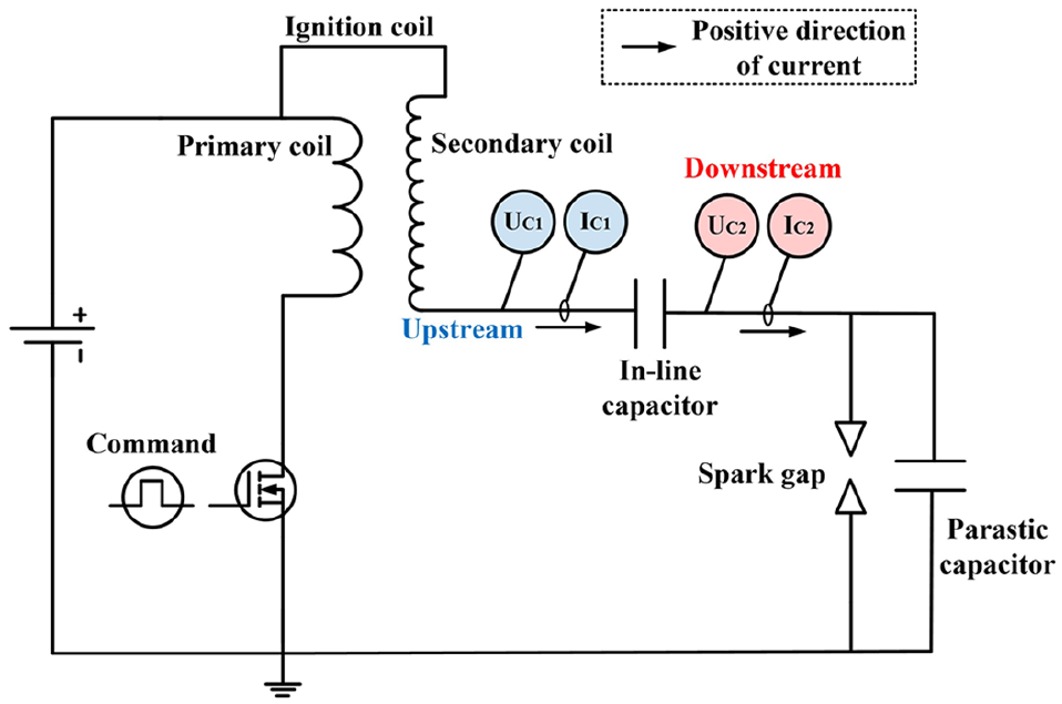
Schematic diagram of the elastic breakdown ignition system.
Specifications of electrical measurement devices.
The experimental investigation therefore leverages the sophisticated control and comprehensive measurements of the advanced research platform, and the working principle of the elastic breakdown concept is explained in subsequent sections with comparison against conventional and other advanced spark ignition strategies; the ignition capability of the new ignition mechanism is thereafter evaluated in optical combustion vessels to highlight the advantages of multi-event and multi-site spark discharge.
Results and discussion
Experiments are first carried out to benchmark conventional and multi-electrode ignition systems through electrical measurements and photographs of the discharge process. The discharge current and voltage profiles of the elastic breakdown phenomena are thereafter demonstrated with the multi-core sparkplug. Further experiments are conducted to examine the elastic breakdown mechanism in detail. Finally, the ignition capability of the new ignition technique is evaluated in optical combustion vessels.
Working principles of conventional and multi-electrode ignition systems
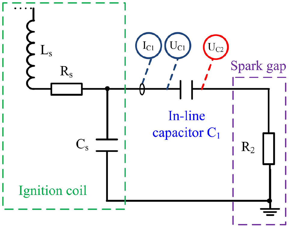
The electrical circuit of a common transistor coil ignition system is shown in Figure 5. There are also sparkplugs featuring additional ground electrodes (represented by the dashed lines in the electric circuit) to improve product durability. Despite the increased number of ground electrodes, the breakdown voltage only establishes a single spark channel connecting the central electrode to the ground electrode in the least resistance path. As the wear of the ground electrode lengthens the spark gap over time, the spark channel migrates to other ground electrodes, thereby enhancing the overall durability. However, the ignition capability is normally compromised because of the increased heat loss from the flame kernel to the multiple ground electrodes.
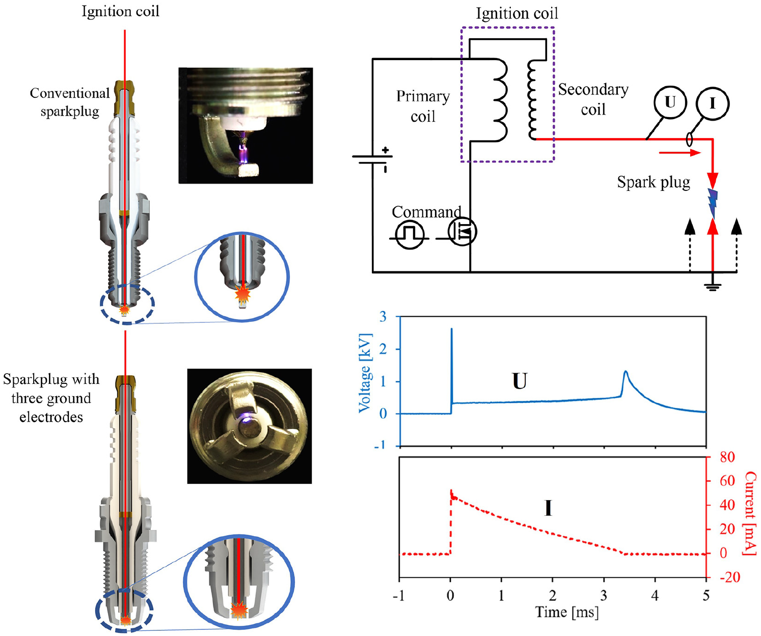
Electrical circuit and discharge waveform of a transistor coil ignition system.
The working principle is the same for these coil-based ignition systems. The charged ignition coil stores sufficient energy prior to the spark event. The electronic ignition driver interrupts the magnetic field at the moment of spark ignition command, which induces a high voltage across the spark gap. A spark discharge between the electrodes occurs once the secondary voltage becomes high enough to breakdown the spark gap. A parasitic capacitor exists in parallel with the spark gap, inherently formed between the central electrode and the cylindrical metal shell due to the capacitive ceramic insulator. This parasitic capacitance provides the primary breakdown energy. Post breakdown, the spark discharge continues with a glow phase discharge with relatively low voltage (e.g. a few hundred volts) but lasting for a few milliseconds. The high-temperature plasma generated in the spark gap ignites the gas mixture that subsequently forms the flame kernel and develops propagating flame front.
In order to enable spark channels at every spark gap, the sparkplug with multiple ground electrodes can integrate a matching number of high voltage electrodes in its core, with careful insulation between each other. An example of the multiple spark sites is illustrated by the photograph and discharge current measurements in Figure 6. Each central electrode of the multi-core igniter is connected to an individual coil, thereby allowing independent control of each pair of electrodes. Such an innovative ignition system has demonstrated strong ignition capabilities. 9 It is noted that, using a single coil connected to all central electrodes will result in a single spark channel established in the least resistance path, similar to that of a sparkplug with multiple ground electrodes. Therefore, the ignition flexibility offered by the multi-core igniter also requires complex control and increased cost, including a greater number of ignition coils and drivers, to operate such an ignition system.
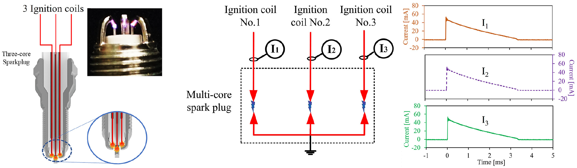
Working principle of multi-core sparkplug.
The elastic breakdown technique developed in this research has a unique advantage of enabling breakdown events at all electrode pairs using only one ignition coil. The modified electric circuit interrupts the direct connection between the ignition coil and spark gaps; therefore, the three electrode pairs work almost independently from each other. As shown in Figure 7, a single coil is used to drive the three-core igniter with additional in-line capacitors to enable elastic breakdown. The secondary voltage (U) starts to oscillate when the driver executes the ignition command on the primary coil side; the voltage measurement in each electrode branch (Ua, Ub, and Uc respectively) manifests breakdown occurrences and discharge processes at all spark gaps. The working principle and basic characteristics are explained and discussed in detail in the next section.
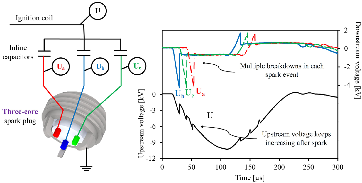
Discharge events at all spark gaps enabled by elastic breakdown technique.
Characterization of elastic breakdown ignition system
Working principle of elastic breakdown
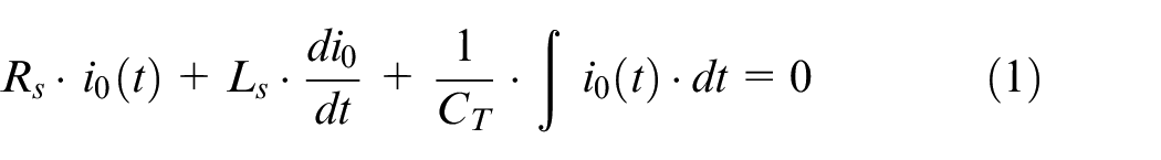
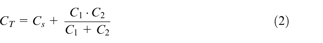
In order to understand the working principle of the elastic breakdown ignition system, experiments are first carried out using a controllable electrical circuit setup that fundamentally represents a production spark ignition system with an addition of selected in-line capacitance of 100 pF. The ignition coil has an inductance of 5 mH on the primary side. Critical parameters of the ignition coil on the secondary side are characterized. As labeled in Figure 8, the secondary coil has an inductance of 30 H, a resistance of 3.26 kΩ, and a parasitic capacitance of 66 pF. The parasitic capacitance of the spark gap is approximately 18 pF. The charging duration is set to 500 μs in this test. Voltage and current profiles are both measured upstream and downstream of the in-line capacitor, respectively. At the first step, an electrical insulator is placed in the spark gap to avoid the breakdown event, and measurements are acquired to show the energy oscillation process.
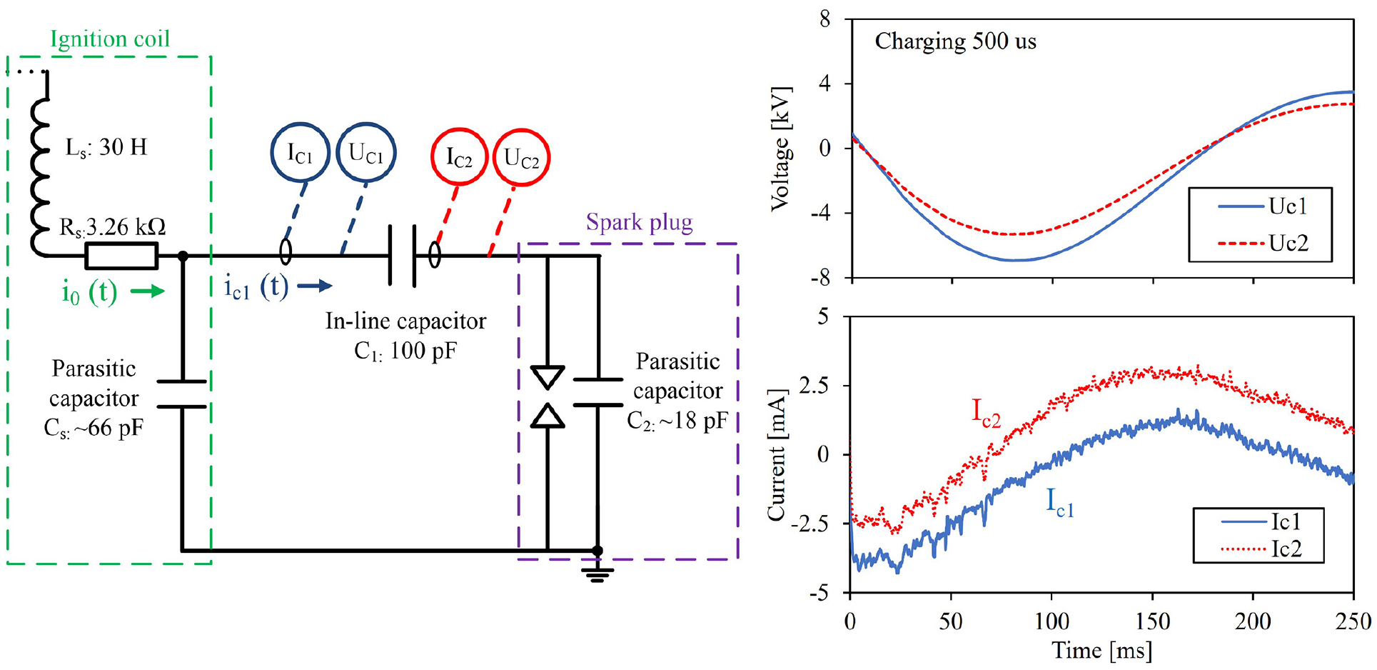
Electrical waveforms of the elastic breakdown system in a void discharge event.
An equivalent RLC circuit is formed by the in-line capacitor (
By solving the second-order differential equation (1), the total discharge current

where
The current upstream of the in-line capacitor
where
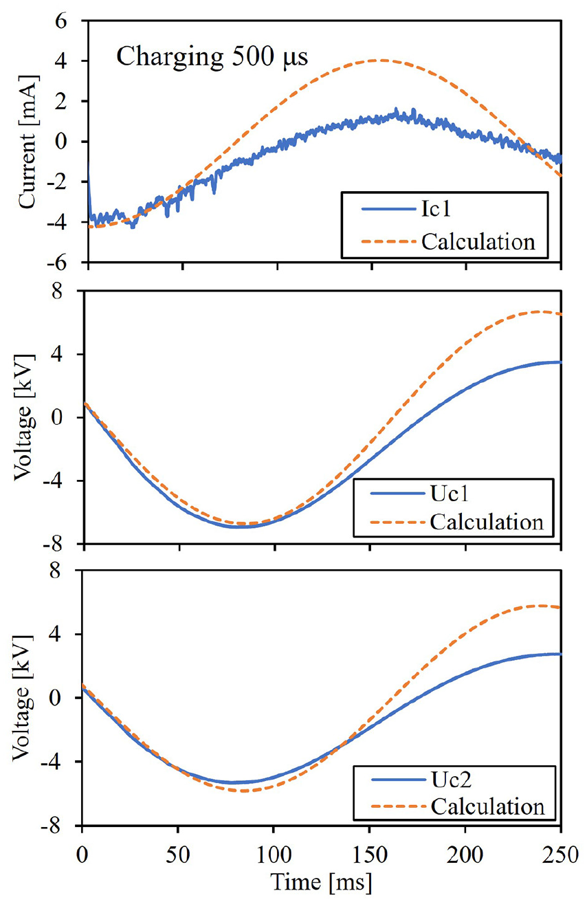
Comparison between measurement and calculation of the discharge profile for the elastic breakdown system in a void discharge event.
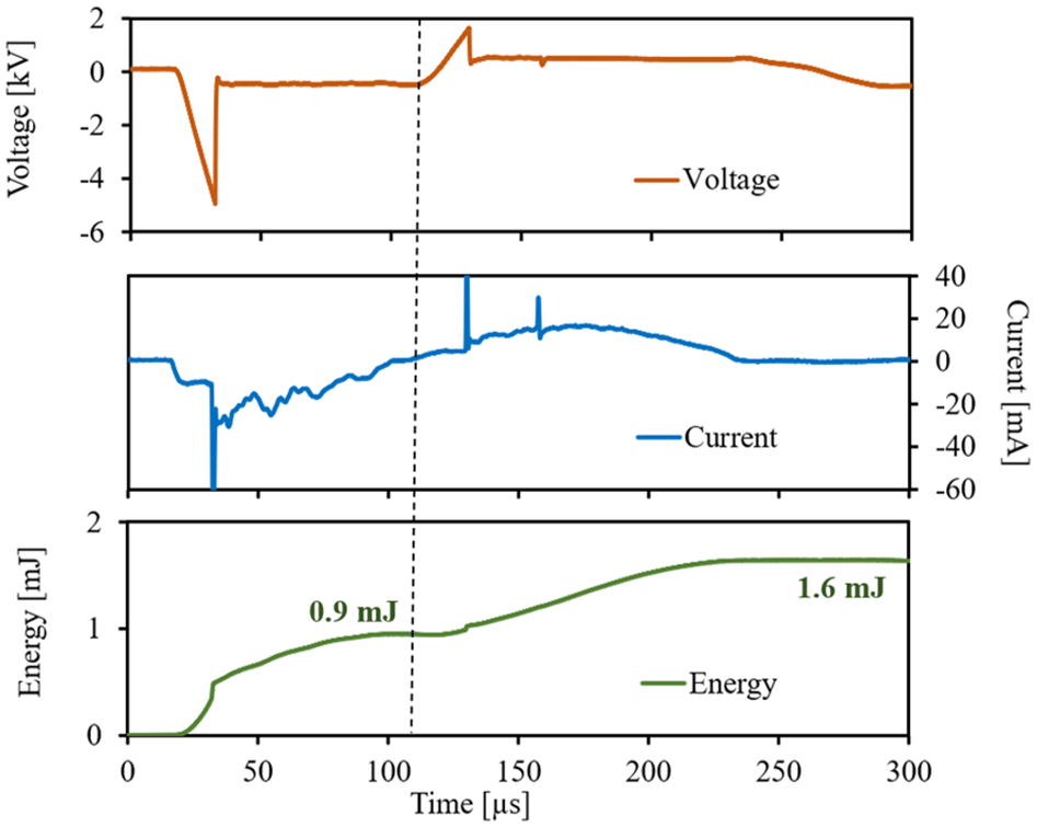
The same experiments are repeated after removing the electrical insulator in the spark gap. Voltage and current measurements are placed upstream and downstream of the in-line capacitor. In order to have successful breakdown events, the charging duration of the ignition coil is set to 1 ms. In addition, these experiments incorporate high-speed imaging synchronized with the electrical measurements to better understand the experiment observations. A typical discharge process of the elastic breakdown is shown in Figure 10. Plots at the bottom right corner present the voltage and current profiles during the spark events, while plots on the left show the zoom-in views of voltage measurements at upstream and downstream of the in-line capacitor. At time zero, the RT-FPGA system sends the ignition command and triggers data acquisition at the same time. The high-speed camera is synchronized to start recording at 100,000 frames per second (fps) and an exposure time of 9 μs for each image.
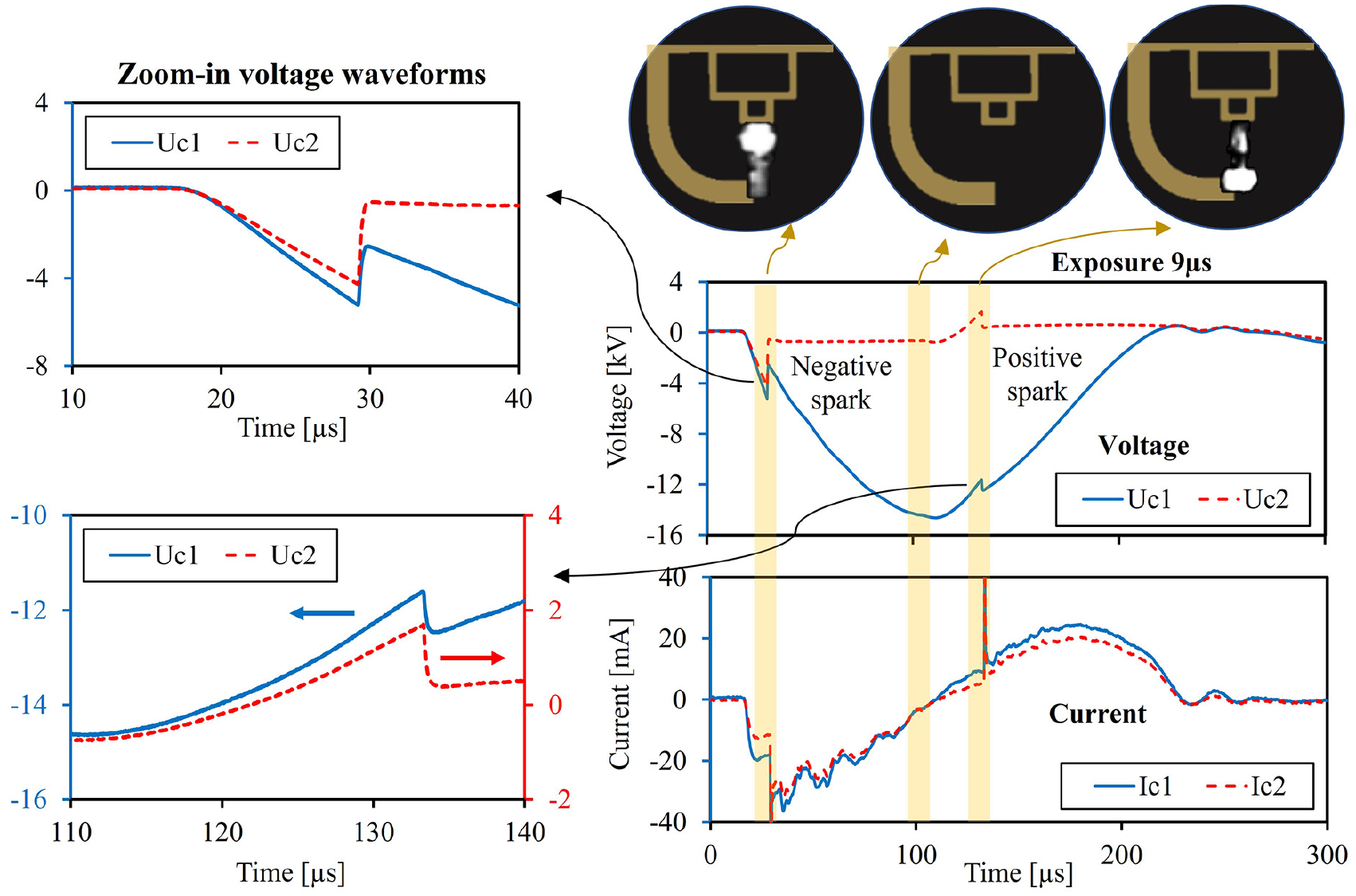
Electrical measurements and high-speed images of a typical elastic breakdown discharge.
As shown by the voltage measurements, both Uc1 and Uc2 start oscillating approximately 15 μs after the ignition trigger and increase in magnitude till around 30 μs time stamp. Prior to breakdown, the voltage pattern is very similar to that of the void discharge shown in Figure 8, and the current measurements also present a classical charging process of capacitors in-series under alternating current (AC). The current and voltage in this pre-breakdown stage are governed by equations (3), (4), (8), and (9), and the equivalent circuit is shown in Figure 11.
Equivalent circuit of the elastic breakdown ignition system in the pre-breakdown discharge stage (0–30 μs).
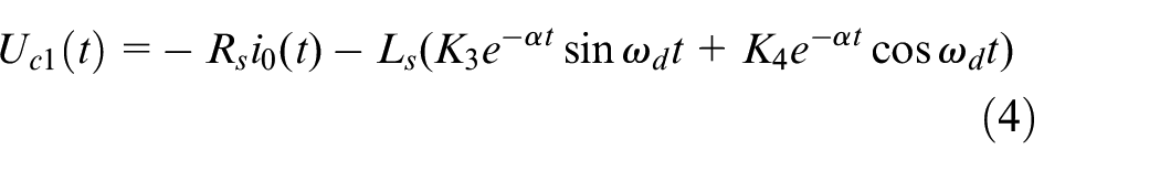
At the time stamp of 30 μs, breakdown occurs as Uc2 reaches the breakdown voltage threshold across the spark gap, and a plasma channel is established. The spark gap thereupon becomes conductive, and Uc2 stops following the trajectory governed by equation (9). Instead, Uc2 decreases in magnitude rapidly at the time of breakdown and then maintains a discharge voltage near −400 V as the discharge process continues, as manifested by the voltage measurements in the time window of 30 to 110 μs. With the plasma channel established, the spark gap can be represented by a resistor, and the equivalent circuit is shown in Figure 12. It is important to note that Uc1 largely remains a sinusoidal waveform during this period, which presents a unique feature of separating Uc1 and Uc2 during the discharge process. Therefore, Uc1 is still governed by equation (4), but its oscillation frequency changes due to the changes in the equivalent circuit and coefficients need to be re-calculated.
Equivalent circuit of the elastic breakdown ignition system in the glow phase discharge stage (30–110 μs).
After the first breakdown, the current magnitude shows a decreasing trend. When Uc1 reaches the valley at ∼110 μs, the current traces cross zero and the spark gap becomes an open circuit, which marks the finish of the first discharge event. The ignition system returns to the equivalent RLC circuit as shown in Figure 11. After passing the valley, Uc1 continues to oscillate but with a positive slope, and Uc2 starts to rise from near −400 V toward the positive direction. The current flow also changes directions.
The voltage oscillation continues, and Uc2 keeps increasing till the positive voltage is high enough to result in another breakdown across the spark gap. It is noted that the amplitude of the breakdown voltage in the second breakdown event appears to be lower than that of the first event; the gas media between the spark gap may be more reactive after the first discharge event, which may contribute to the breakdown voltage difference. After the second breakdown, Uc2 maintains at about 400 V till the end of the second discharge event. The equivalent circuit of the positive glow phase can also be represented as in Figure 12. It is noted, however, that the voltage polarity at the spark gap changes from negative to positive.
After solving the coefficients for each stage during the breakdown events, comparisons between the measured current and voltage waveforms and the calculation results are plotted in Figure 13. As shown, the governing equations can well capture the overall trends and characteristics of the breakdown events. The calculation details are included in the Appendix.
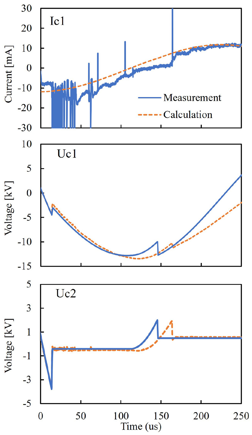
Comparison between measurement and calculation of elastic breakdown events.
The breakdown and discharge processes are captured by the high-speed images. By convention, the ground electrode of the sparkplug is considered to have zero voltage potential. During the first breakdown and discharge process, the high voltage electrode works as a “cathode” since it has a negative voltage potential relative to the ground electrode, and thus the first breakdown and discharge process is considered as a negative spark event. Similarly, the second breakdown and discharge process are deemed as a positive spark event because the voltage of the central electrode rises to positive relative to the ground electrode and the high voltage electrode becomes an “anode.” Generally, the glow observed in the vicinity of the cathode and anode is called cathode glow and anode glow, respectively. 35 The high-speed images have also captured distinct differences between the cathode glow and anode glow in the two spark events. It is observed that both shape and brightness of the cathode glow differs from that of the anode glow. The cathode glow shift from high voltage electrode to ground electrode when the polarity of the high voltage changes from negative to positive. During the transition period where Uc1 reaches its peak value and Ic1 passes zero, the high-speed image also confirms that the plasma channel does not sustain. Therefore, the elastic breakdown technique has demonstrated its capability of enabling multiple spark events with one ignition coil and a single spark trigger, as evidenced by the voltage and current measurements and the synchronized high-speed images.
With the voltage and current measurements, the discharge energy can be calculated using equation (10).
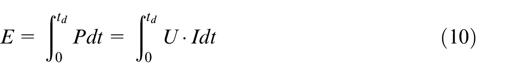
where E is the energy in a discharge event, P is the discharge power, U and I are the measured discharge voltage and current, td is the discharge duration. The discharge energy is plotted in Figure 14 along with the discharge voltage and current in the exemplary case shown in Figure 10.
Discharge energy of elastic breakdown ignition.
Inclusion of the in-line capacitor adds another variable in controlling the discharge energy. In conventional coil-based ignition system, the discharge energy is usually controlled by regulating the charge duration. In the elastic breakdown ignition setup, the in-line capacitance effectively determines the energy storage and charging profiles of the capacitor, and thus impacts the discharge energy released during the spark events. Figure 15 shows the calculated discharge energy as a function of the charging duration at three levels of in-line capacitance (plots on the left), along with the discharge energy profiles at 4 ms charge duration (plots on the right). Similar to conventional ignition systems, the elastic breakdown ignition delivers higher discharge energy when the charging duration is prolonged. Moreover, the use of a greater capacitance can also increase the discharge energy.
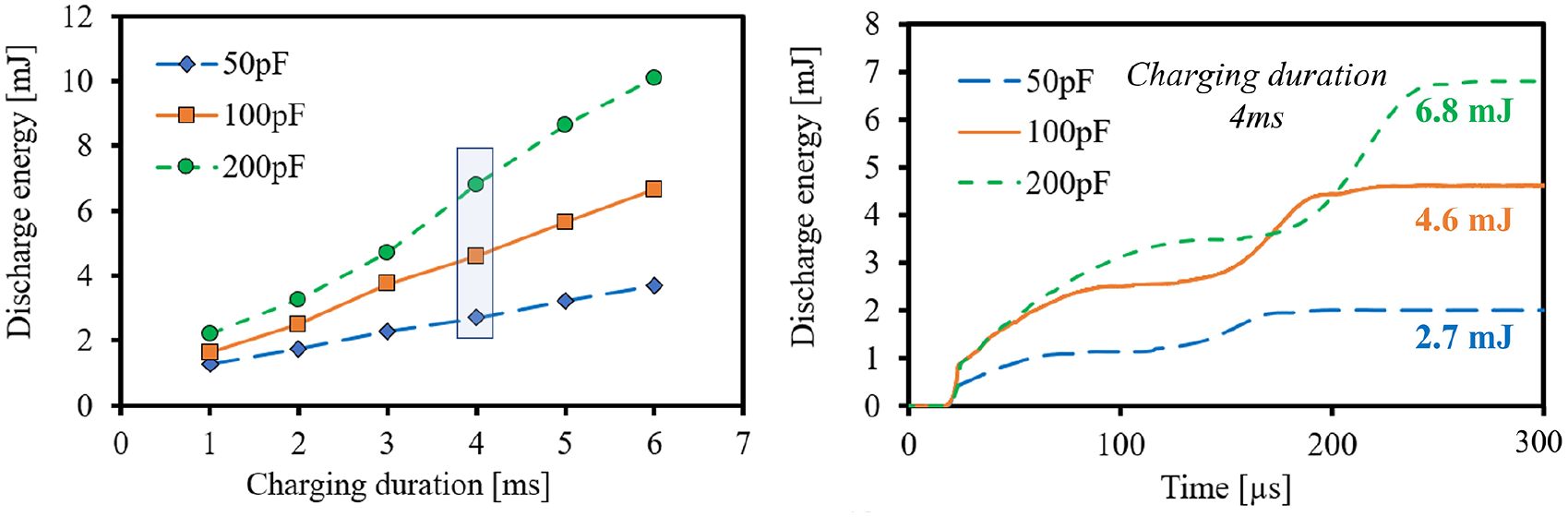
In-line capacitor impacts on discharge energy.
Elastic breakdown ignition to generate multiple spark events at multiple sites
As mentioned earlier, the multi-core ignition system requires a matching number of coils to enable spark events at all electrode pairs; however, the elastic breakdown technique offers advantage of using only one set of ignition coil. When connected to the multi-core igniter, the elastic breakdown circuit comprises a dedicated in-line capacitor for each electrode pair, thereby allowing the voltage at each spark gap to act almost independently from others, because breakdown occurrence at any electrode pair does not result in short circuit at any other pairs. An example of the experimental results is shown in Figure 16. Essentially, the breakdown and discharge process as described in the last section (Figure 14) takes place at each electrode pair of the multi-core igniter. The breakdown voltage varies among spark gaps and between breakdown events due to gap differences and condition changes, for example, the gap size and ionization activity, and therefore multiple breakdown events occur in a seemingly stochastic manner.
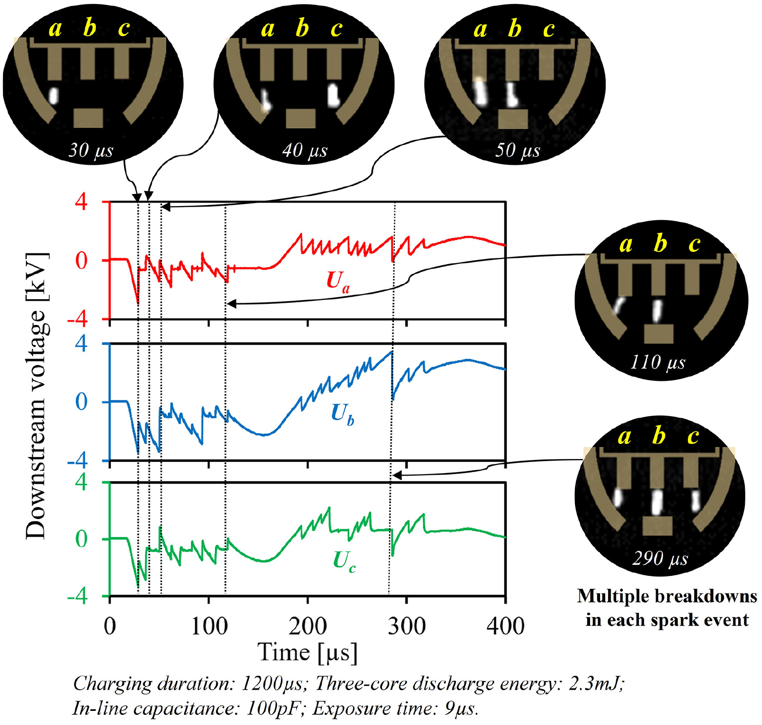
Multiple sparks generated by elastic breakdown strategy with multi-core igniter.
Although the individual voltage measurement receives noise interference from breakdown at other electrode pairs, the high-speed images are helpful to identify and correlate the breakdown events with the associated voltage waveforms. In this experiment, the optical setup leverages the image intensifier to enable clear imaging of breakdown and discharge with an exposure time of 9 μs. As shown in Figure 16, both negative and positive breakdown events are captured at all three spark gaps. The camera captures the first appearance of a plasma channel at 30 μs in spark gap “a”; the discharge sustains till 110 μs, as evidenced by subsequent high-speed images. The breakdown and discharge in spark gap “b” resemble those in spark gap “a” but occur ∼20 μs later as shown in the image at 50 μs. The spark event in spark gap “c” is first observed at 40 μs, and the plasma channel disappears at 50 μs, manifesting a very short spark event. As the spark voltage turns to positive, the high-speed image at 290 μs, as an example, demonstrates spark occurrence at all three electrode pairs simultaneously.
Performance of multi-site elastic breakdown ignition
Combustion tests under quiescent condition in the optical combustion vessel are carried out to examine the ignition capability of the multi-core elastic breakdown strategy. The experiments also include testing with a conventional spark ignition system for comparison. Methane and air are premixed at an excess air ratio of 1.4, and the combustion vessel is charged to a pressure level of 4 bar at 25°C. Although the temperature effect is not simulated, the density of the gas mixture in the combustion vessel is estimated to be equivalent to that of an engine cylinder charge at 10 bar during the compression stroke. The ignition setup uses the same ignition coil for fair comparison.
High-speed imaging is used to visualize the spark and flame, and the time instant of spark breakdown is assigned as “0 ms.” In Figures 17 and 18, comparisons of ignition and flame propagation are shown for charging durations of 1 and 6 ms respectively. Both ignition systems have successfully ignited the lean methane-air mixture. It is important to note that the multi-core elastic breakdown ignition generates more than one flame kernel near the sparkplug, thereby contributing to faster flame propagation. Such an effect becomes more obvious as the charging duration is increased from 1 to 6 ms.
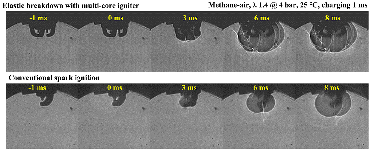
Comparison of ignition and flame development in combustion vessel (charging duration 1 ms).
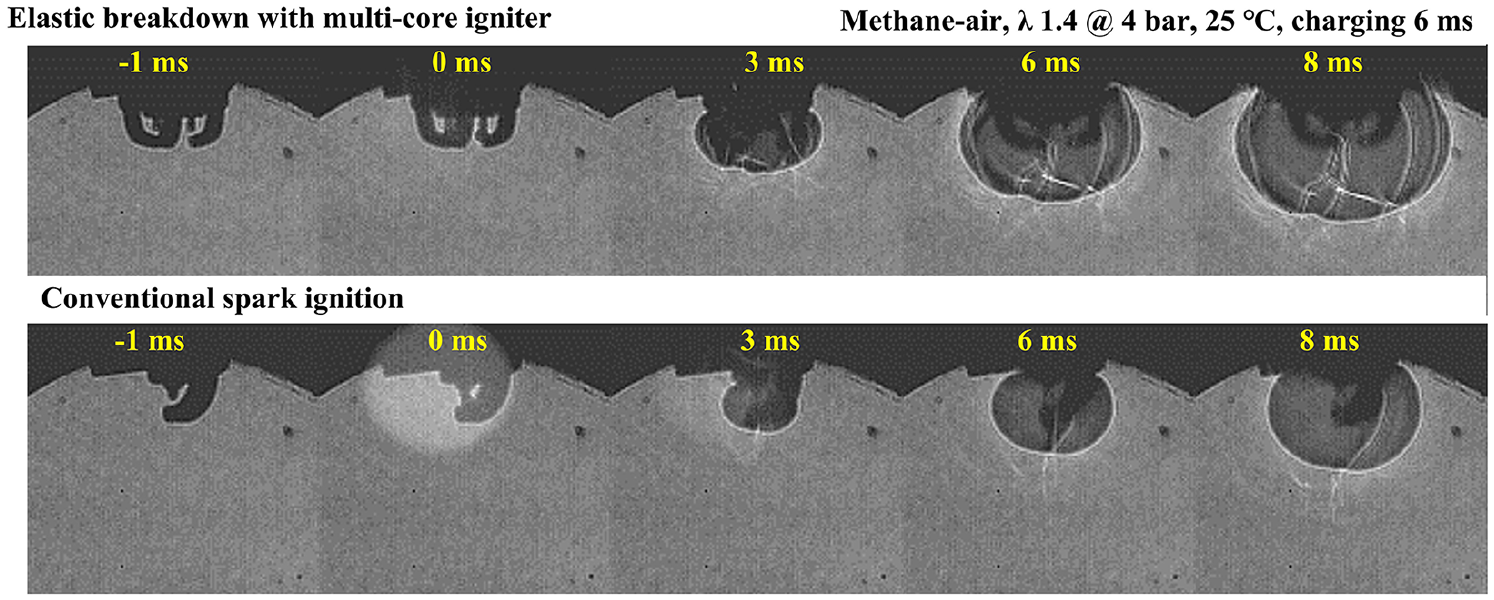
Comparison of ignition and flame development in combustion vessel (charging duration 6 ms).
Under the tested conditions, increasing the charging duration of the conventional ignition system results in minor improvements in flame kernel formation and flame propagation, whereas the multi-core elastic breakdown ignition forms a larger flame kernel and a greater ignition volume. The flame area is calculated for each case and the comparison is shown in Figure 19. Compared to the conventional ignition cases, the calculated flame area of the new ignition system increases by 50% and 100% at 1 and 6 ms charging time, respectively.
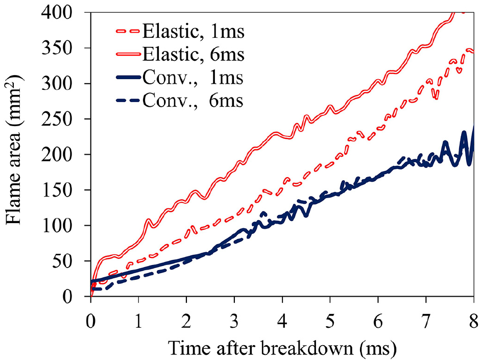
Calculated flame area comparison between elastic breakdown and conventional ignition.
Additional considerations and future work
Experiments and analyses in previous sections show that the discharge duration of the elastic breakdown ignition is noticeably shorter than that of the conventional ignition mechanism. The in-line capacitor allows Uc1 to continue oscillating while breakdown occurs downstream, thereby enabling possibilities of subsequent breakdown events; however, the in-line capacitor limits the energy passing to the spark gap during each discharge. As a result, the elastic breakdown ignition generally releases lower energy than that of conventional ignition systems. The success of ignition requires, among other things, that the delivered ignition energy meets the minimal ignition energy demand for self-sustained flame kernel formation. Nonetheless, once the minimal ignition energy requirement is met with a safety margin, additional spark energy makes diminishing contributions to ignition improvements, whereas increasing ignition volume and thus the initial flame kernel size become more effective to accelerate flame propagation. Therefore, the multi-core elastic breakdown can take advantage of the volume ignition at multiple sites, provided that it can deliver enough ignition energy. Further studies will be carried out to identify the ignition energy requirements for different fuel/air mixtures under different operating conditions, as well as methods to increase the discharge energy of the elastic breakdown. The enabling of multi-event multi-site spark ignition are expected to be more beneficial when mixture heterogeneity and strong flow exist near the sparkplug, as the new ignition technique increases the chance of contact between spark channels and mixture pockets more favorable for ignition, in both temporal and spatial domain. Moreover, experimental results also show a potential of controlling the elastic breakdown duration via charging duration and capacitance matching. Strategies can thereafter be developed to predict and control the breakdown timing and the number of breakdown events.
Conclusions
In this research, the elastic breakdown ignition system is studied with detailed current and voltage measurements in systematic experiments to understand the electrical characteristics, in comparison with the conventional and advanced multi-electrode ignition systems. Analyses of the experimental results have revealed the working principle and identified the governing equations of the elastic breakdown process. A series of elastic breakdown events under one spark trigger command have been demonstrated via high-speed imaging techniques. In addition, elastic breakdown events at multiple electrode pairs of a multi-core sparkplug have been established using only one spark coil. Ignition experiments in combustion chambers have proved the capability of the elastic breakdown ignition system to secure the ignition of the air-methane mixture. The major findings and contributions are summarized as follows.
Fundamentally, in order to enable multiple breakdown events, the voltage at the spark gap needs to reach the breakdown voltage multiple times. The secondary voltage oscillation in conventional ignition event finishes once breakdown occurs, and the secondary voltage magnitude reduces, resulting in only one possible breakdown occurrence within a single ignition event. The integration of an in-line capacitor into the secondary coil circuit preserves the secondary voltage oscillation upstream of the in-line capacitor while breakdown occurs downstream of the in-line capacitor at the spark gap, allowing the voltage at the spark gap to build up again after one breakdown and thus enabling subsequent elastic breakdown events. It is then possible to energize multiple spark gaps using a single ignition coil with single spark command.
The first breakdown event of the elastic breakdown ignition is similar to that of the conventional ignition, where a negative breakdown is typically enabled by the negative voltage at the spark gap. However, as the spark voltage builds up again in the elastic breakdown system, it is possible to generate positive breakdown events as the voltage changes polarity and the current flows in the opposite direction. The negative and positive spark events have been validated by matching high-speed imaging and voltage/current measurements.
This research has demonstrated multiple breakdown occurrences in an electrode gap upon one spark command. It is the first time that an ignition system uses only one spark coil with the multi-core igniter to enable a series of breakdown events at multiple sites.
The working principle of the elastic breakdown is explained in detail for the first time, with governing equations identified for each stage in the ignition process. The calculation of voltage and current can capture the overall trend and oscillation period of the elastic breakdown events.
In the preliminary combustion chamber tests, the elastic breakdown ignition with multi-core sparkplug outperforms the conventional ignition system by offering faster burning of the methane-air mixture, mainly contributed by the multiple flame kernel initiated. As demonstrated by the high-speed images of the flame kernels, the flame area nearly doubles with the new ignition system with 6 ms charging duration.
Footnotes
Appendix
Declaration of conflicting interests
The author(s) declared no potential conflicts of interest with respect to the research, authorship, and/or publication of this article.
Funding
The author(s) received no financial support for the research, authorship, and/or publication of this article.