
Abstract
The development, modelling and testing of a novel, fuel-efficient hydraulic hybrid light truck is reported. The vehicle used a Digital Displacement® pump/motor and a foam-filled hydraulic accumulator in parallel with the existing drivetrain to recover energy from vehicle braking and use this during acceleration. The pump/motor was also used to reduce gear-shift times. The paper describes the development of a mathematical vehicle model and the validation of this model against an extensive testing regime. In testing, the system improved the fuel economy of the vehicle by 23.5% over the JE05 midtown drive cycle. The validated mathematical model was then optimised and used to determine the maximum fuel economy improvement over the diesel baseline vehicle for two representative cycles (JE05 midtown and WLTP). It was found that the hybrid system can improve the fuel economy by 24%–43%, depending on the drive cycle. When this was combined with engine stop-start, the system improved the fuel economy of the vehicle by 29%–95%, depending on the drive cycle.
Keywords
Introduction
The hybridisation of both new and existing vehicles is considered to be crucial if the world is to meet the emissions targets set for transportation. 1 A range of technologies are available for this hybridisation and previous analysis has shown that hydraulic hybridisation is best for some goods vehicles. 2 In future it may be possible to use heavy goods vehicles with steerable axles3–5 for long-haul and extra-urban delivery, and light goods vehicles could be used for ‘last mile’ deliveries in difficult-to-manoeuvre town centres or suburban neighbourhoods. 6
Light goods trucks are defined here as commercial vehicles with a fully laden mass of 6600 kg or less and which have a separate cab and cargo compartment, unlike a van. Previous research has investigated electric7–10 and series hydraulic hybridisation11–16 of similar vehicles. However, previous research has focussed on simulation models or engine-in-the-loop17,18 experiments to validate the model and evaluate the system benefits.
This paper presents a unique and significant contribution in that it reports the development of a computer model of a diesel-engine parallel hydraulic hybrid light goods truck; the use of this model to specify the system; the validation of the model against a suite of full-vehicle tests in a controlled environment; and the use of the model to determine the maximal benefits of hybridisation for two drive cycles, the JE05 Midtown and the Worldwide Harmonised Light Vehicles Test Procedure (WLTP).
This is the first time that Danfoss’ Digital Displacement® technology has been used to parallel-hybridise a vehicle through the power take-off, the first time that a truck has been hybridised with this technology, the first time such a vehicle has been tested under controlled conditions and had its fuel consumption measured and used to validate a vehicle model. Parallel hybridisation was chosen because it allows after-market hybridisation of the vehicle, improving the flexibility of the solution.
A Danfoss Digital Displacement® pump/motor (DDPM) was chosen by the vehicle manufacturer because of its superior controllability and much reduced losses when compared to conventional hydraulic pump/motor technologies such as a swashplate pump/motor. A 3D overview of a DDP (Digital Displacement® Pump, similar to a DDPM) with cutaway is shown in Figure 1 and a section drawing showing labelled components is shown in Figure 2. The operating principle of a DDPM is similar to that of a DDP, except that the DDPM has been modified to produce both motoring and braking torque.
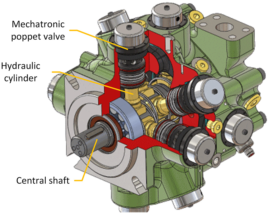
Isometric cutaway of a DDP (the DDPM used in this study was similar to the model shown here).
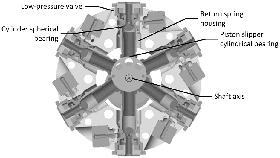
Section view detail showing the operating parts of a DDP, after Caldwell. 19
In previous studies, the DDPM has been shown to be 20%–50% more efficient than a comparable swashplate pump over a given cycle. 19 In addition, due to the fast-acting computer-controlled mechatronic valves used in the DDPM, the machine can respond to control input more quickly than the traditional mechanical swashplate pump 20 used in other hydraulic hybrid vehicles.
System modelling and specification
A schematic of the vehicle showing the added hydraulic hybrid components is given in Figure 3, where the pump/motor (P/M) is a Digital Displacement® pump/motor (DDPM) manufactured by Danfoss and is connected to the gearbox power take-off (PTO). The PTO is effectively a clutched splined shaft that is connected to the vehicle’s drivetrain.
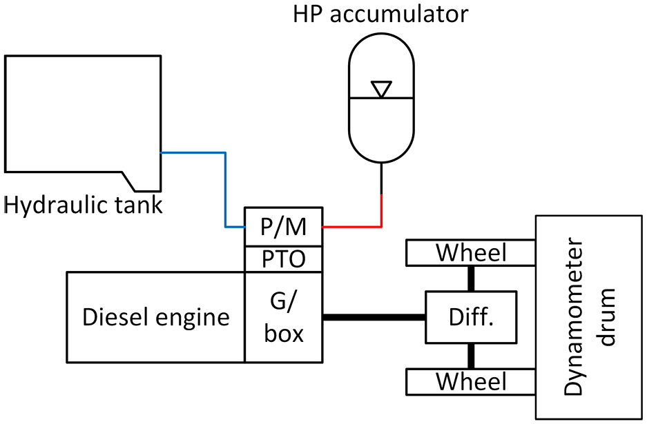
Schematic showing the layout of the experimental vehicle.
The mechanical components (vehicle drivetrain and diesel engine) were left unaltered for this conversion. Accelerating and braking torque is generated by the P/M and the hydraulic circuit (see Figure 3), which is controlled by the hydraulic system controller (see Section 2.2). This torque is transmitted through the PTO to the vehicle drivetrain to accelerate or decelerate the vehicle.
To specify the test system’s properties, such as accumulator pre-charge pressure and accumulator volume, a detailed model of the vehicle that combined both mechanical and hydraulic components was built in MATLAB/Simulink.
Mechanical modelling
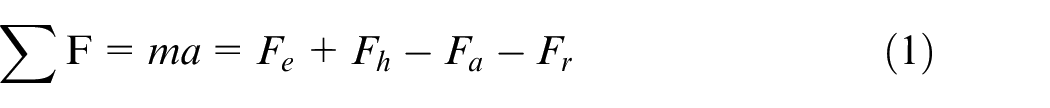
The mechanical model of the vehicle is a backward-facing model similar to Markel et al. 21 and Guzzella and Amstutz, 22 where the load on the engine is determined by working backward from the wheel torque required to match the desired speed. The forces acting on the vehicle are calculated from aerodynamic drag, rolling resistance and the torque generated by the engine:
where

where A,
Key model parameters.
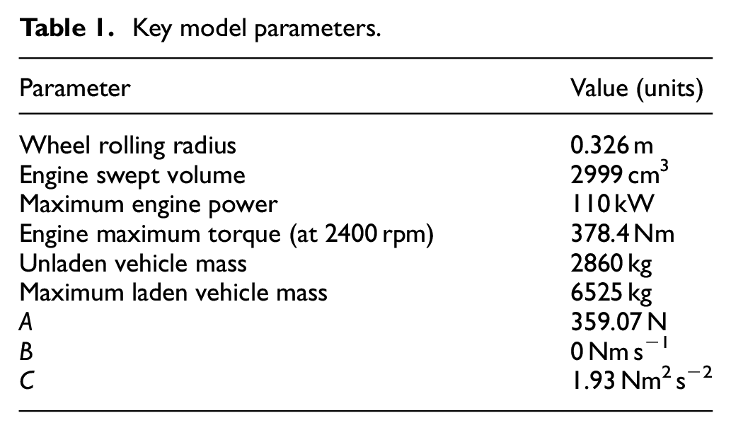
Gradient forces were neglected in both testing and modelling. Further details of the model, such as detailed equations and methodology, can be found in Taylor et al. 23
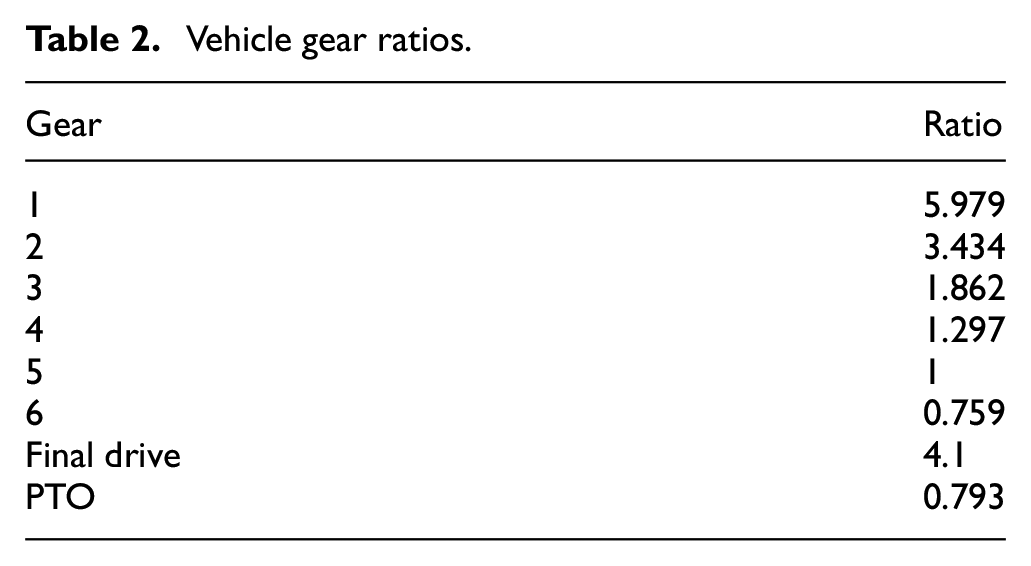
The vehicle manufacturer supplied an engine map of the vehicle, which gave the fuel consumed by the engine at a range of torque-speed points. This was incorporated into the model to provide the total fuel used over a given drive cycle (see Figure 4). Also included in the model was a gearshift map, as specified by the vehicle manufacturer, which allowed for modelling the realistic shifting of the automated manual transmission (AMT), the inertia of the drivetrain of the vehicle and the losses of the differential, gearbox and PTO, to which the DDPM is connected. Key parameters for the vehicle model are given in Table 1, and the gear ratios for the vehicle are given in Table 2.
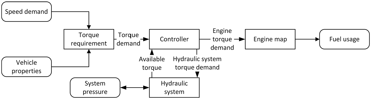
Backward-facing model schematic.
Vehicle gear ratios.
Hydraulic modelling
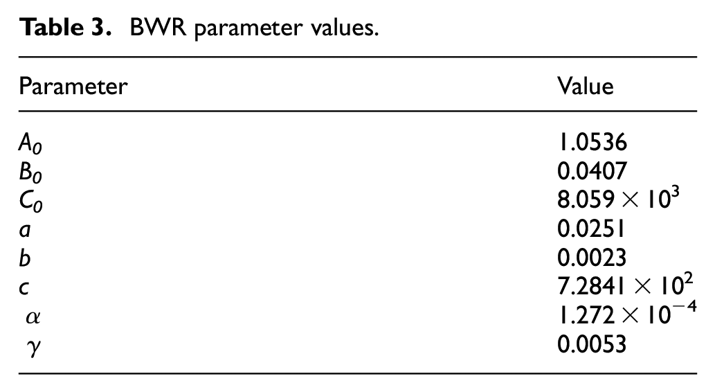
The simulation included detailed models of the hydraulic system, comprising a high-pressure (HP) nitrogen-filled bladder accumulator, the DDPM and a hydraulic system controller. The state of bladder accumulator was modelled according to the Benedict-Webb-Rubin equation of state 24 :
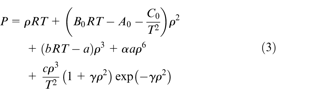
where P is the instantaneous pressure,
BWR parameter values.
The DDPM was modelled by a validated semi-empirical loss model taken from previous studies.19,29,30 The efficiency map of the DDPM at 200 bar is given in Figure 5.
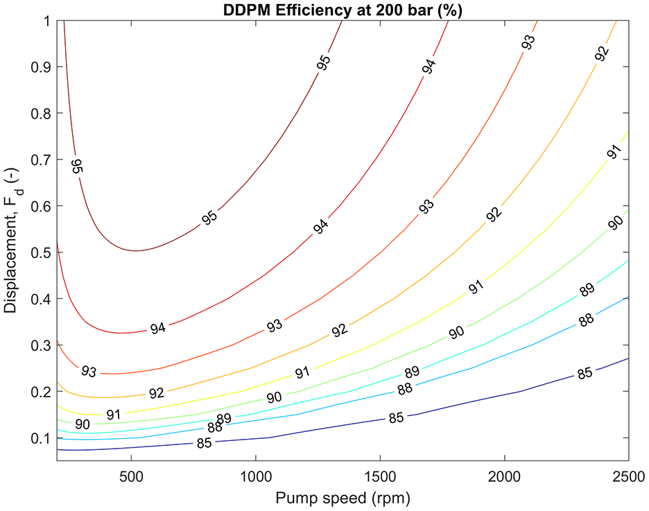
Measured mechanical efficiency map for the Danfoss DDPM at 200 bar.
Controller
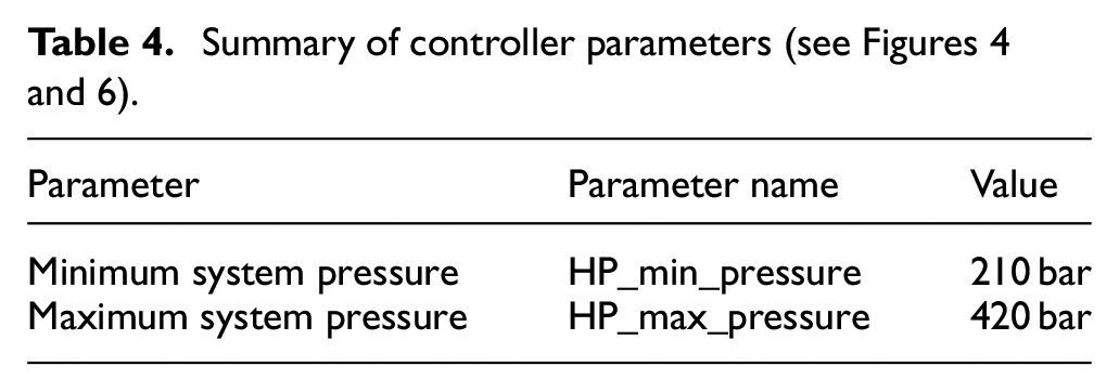
Also modelled was the system controller, which was responsible for controlling the DDPM. The controller uses a greedy algorithm 31 to control the hydraulic system, with additional logic to reduce high-frequency mode cycling. If the torque request from the driver is negative (braking torque) and the high-pressure (HP) accumulator is below its maximum pressure, the system pumps fluid from the tank to the HP accumulator using the DDPM. This reduces the load on the traditional friction brakes and stores the recovered energy in the HP accumulator. The maximum HP accumulator pressure is set by the limit of the equipment, in this case it was 420 bar.
The minimum HP accumulator pressure (

where the HP pre-charge pressure (
When the driver demands positive (driving) torque and the HP accumulator is above its minimum set pressure, the system uses the energy stored in the HP accumulator to provide driving torque and return fluid to the tank. A pseudocode implementation of this greedy control algorithm is given in Figure 6 and the relevant parameters for the controller are given in Table 4.
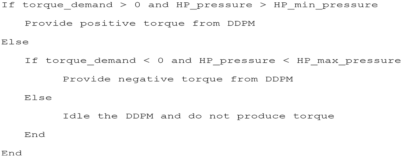
Pseudocode describing control system operation.
The DDPM has a separate controller that regulates the timing of the valves for each cylinder in response to a torque demand from the system controller. This controller uses a sigma-delta algorithm 19 to decide which cylinders to enable on a stroke-by-stroke basis, based on the demand.
System specification
The simulation model of the hybrid vehicle was used to find the optimal parameters for the various hydraulic components. The parameters that could be changed were the displacement of the DDPM; the pre-charge pressure (i.e. pressure in the accumulator when there is no hydraulic fluid present) of the high-pressure accumulator; and the volume of the high-pressure accumulator.
Parameter-sweep optimisation was used to determine the pre-charge pressure, accumulator volume and pump displacement that gave the lowest fuel consumption over the JE05 drive cycle. In all cases the model started and ended with the same pressure (i.e. stored energy) in the high-pressure accumulator, to ensure that no undue benefit was gained from the difference in stored energy at the beginning and end of the cycle. 32 The graphs showing sweeps of pre-charge pressure, accumulator volume and pump displacement are given in Figure 7.
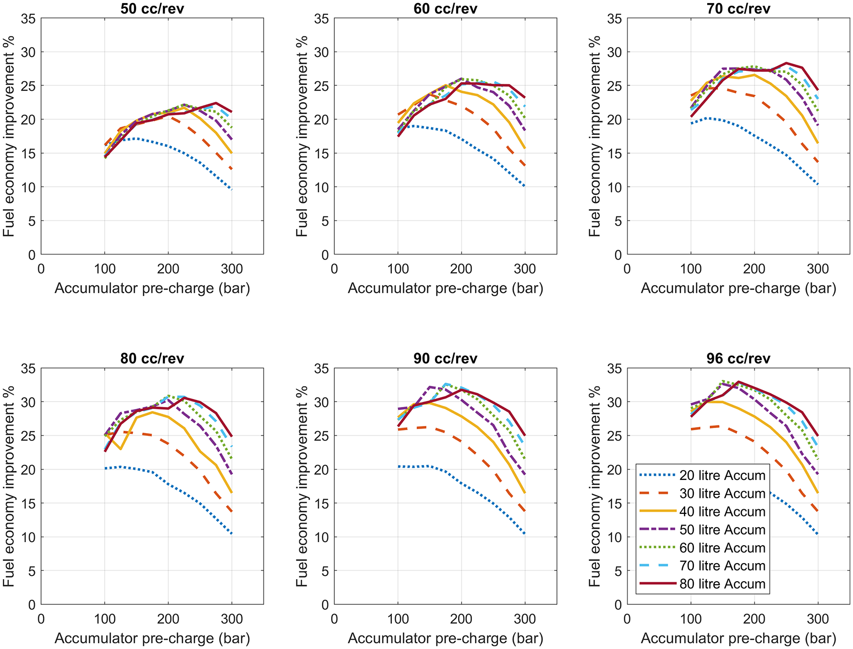
Parameter sweeps over the JE-05 midtown cycle for accumulator pre-charge pressure and accumulator size for different pump sizes in cubic centimetres per revolution (cc/rev).
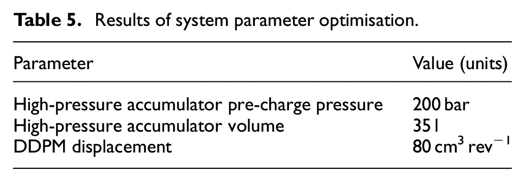
The sweeps in Figure 7 show that higher displacements result in higher energy savings, but this has diminishing returns with displacements larger than 80 cm3 rev−1. The optimal pre-charge pressure for this displacement was at 200 bar, and an accumulator volume of 35 l was chosen since larger volumes gave diminishing returns and would have been difficult to package in the chassis.
The final system properties are given in Table 5, below. The system model predicted a 28% fuel economy improvement over the JE05 drive cycle for the given parameter set.
Results of system parameter optimisation.
System testing
The hybrid system was retrofitted to a light goods truck and was tested on a rolling road dynamometer. Note that the PTO could be disengaged with a solenoid valve, thus allowing baseline tests and hybrid tests to be run sequentially. A photo showing the underside of the vehicle under test is given in Figure 8.
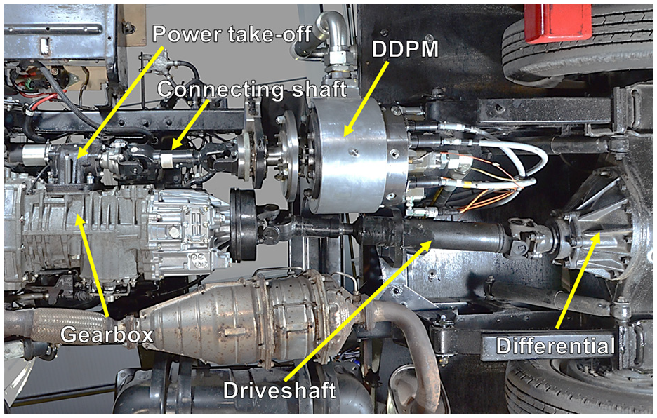
Image of test vehicle from below, showing power take-off and DDPM (Digital Displacement® pump/motor).
Test set-up
The resistance force generated by the dynamometer was given by equation (1), and the values for the dynamometer coefficients are given in Table 1.
A range of parameters were measured during the tests, as shown in the schematic in Figure 9. These values were logged by a Dewesoft datalogger at a maximum frequency of 5 kHz. Desired fuel rate was measured from the vehicle’s controller area network (CAN), which was fitted against total fuel dispensed to give an empirical formula for instantaneous fuel usage. An adjustment was made to the fuel consumption to account for the power used by the datalogging equipment, as it was powered off the vehicle’s alternator.
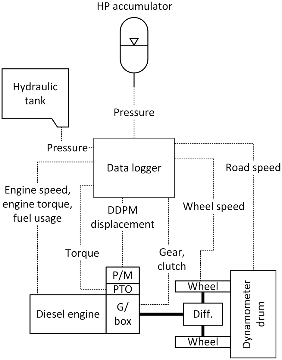
Schematic showing signals logged during testing.
The same professional driver was used for all the tests. The driver was given a speed demand to follow and upper/lower limits of speed error, as is typical in drive cycle testing. The tests were run three-at-a-time, with a warm-up test cycle before the first cycle to ensure the running gear, engine and hydraulic fluid were up to temperature.
The testing campaign was time-constrained, and so it was restricted to only the urban or ‘midtown’ part of the cycle (644–1409 s). This was the part of the cycle over which it was assumed that the system would provide the greatest benefit. However, the system had been specified (see Section 2 above) for the whole JE05 cycle and so was not optimal for the truncated cycle used during testing.
System improvements
The DDPM was used to decrease the time in which the AMT could change gear, increasing the driveability and performance of the vehicle. Under normal conditions, the AMT waited for the engine speed to increase or decrease to match the drivetrain rotational speed, assisted by the synchroniser rings. In the test vehicle, the DDPM was used to speed up or slow down the engine more quickly than would have been possible using traditional engine controls (additional fuel to speed up the engine, waiting for friction effects to slow down the engine). This had not been implemented or tested in previous iterations of parallel hydraulic hybrids with Danfoss technology. 23 In addition, the DDPM used in this application allowed the implementation of engine stop-start (i.e. stopping the engine when idling and re-starting the engine when accelerating), which was not possible with previous DDPM hybrid implementations.
The DDPM used a novel form of closed loop timing control, which continually monitored the status of individual valves, making micro-adjustments to the actuation timing on a stroke-by-stroke basis to ensure efficient use of the stored energy.33,34 In addition, when certain events at the PTO shaft were predicted (such as gear shifts), valve timing was further adjusted in a feed-forward manner to reduce latency in the DDPM’s response. This control was implemented on the Danfoss AMC2 controller 23 and displacement demand was satisfied using the previously described sigma-delta 19 control algorithm.
Test results
The speed, pressure and total fuel consumption results from one of each of the cycles (with and without the hydraulic hybrid system) are given in Figures 10 to 12, respectively. The professional driver was demonstrated to drive consistently, with the standard distribution of total distance for all cycles of 0.3%.
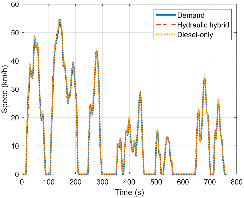
Vehicle speed traces from testing (demand – JE05 ‘midtown’ section).
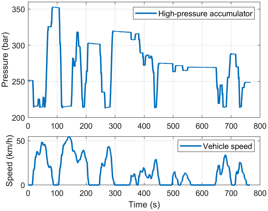
Pressure in the high-pressure accumulator during a test cycle.
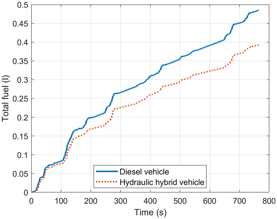
Measured fuel consumption for the diesel engine only and the hybrid vehicles over one JE05 midtown test cycle.
In Figure 11 the HP accumulator pressure is shown with the vehicle speed. As is expected for a hydraulic hybrid system, when the vehicle decelerates, fluid is pumped from the tank into the HP accumulator. Similarly, when the vehicle accelerates, the high-pressure fluid is used to provide torque and is returned to the tank, lowering the pressure in the high-pressure accumulator.
Also clear from this figure is the effect of cooling in the gas in the accumulator’s bladder. When fluid is forced into the accumulator, the gas in the bladder is compressed, causing it to increase in temperature. When the vehicle is stationary, for example between 292 and 354 s, the gas slowly cools as energy is dissipated, reducing the pressure in the accumulator and therefore the stored energy. The rate of this dissipation was minimised by using foam-filled accumulators, as described in Section 2.2.
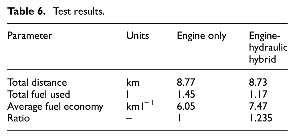
The fuel consumption of each of the two vehicles over the three back-to-back JE05 ‘midtown’ drive cycles are given in Figure 12. This figure shows the marked difference in fuel consumption between the two vehicles, with the hydraulic hybrid using 19.1% less fuel for this single cycle. Full results for the differences in fuel consumption are given in Table 6, which shows that the hydraulic hybridisation increases fuel economy by 23.5% when averaged out over the three back-to-back cycles. This was less than expected from modelling done before the test campaign.
Test results.
Model validation
Diesel engine-only model validation
The diesel-only version of the model was validated against test data as described above. The results of this validation are given in Figure 13. The fuel economy was 6.14 km l−1, compared to 6.05 km l−1 for the test, which means the model over-estimated by 1.6%, which is a reasonable fit for a quasi-static model. There may be opportunities to further improve the model by adding transient effects and engine inertias.
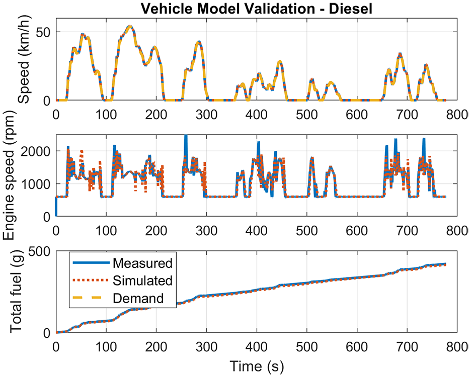
Validation of diesel engine only model.
Hydraulic hybrid model validation
Key differences between the model and actual vehicle
During testing it was found that there were some differences between the vehicle model developed above and the test vehicle. Most notable was the gear shift strategy. In the initial simulations it was assumed that it would be acceptable to shift down to any gear as soon as braking was requested, in order to give the best gearing for energy recovery. However, this gear shift strategy was not acceptable due to its impact on driveability as the driver may request braking for a short time and then demand acceleration. The gear would then need to shift back up to match the engine speed, and this would incur an unacceptable delay. The speed/displacement calculations used to specify the DDPM were based on the incorrect gear shift strategy. Instead, a larger-displacement DDPM could have been installed on the vehicle. It is likely that this larger-displacement DDPM would have increased the fuel economy, and this assumption is explored further in the following sections.
Additionally, the engine was programmed to increase fuelling during downshifts to assist with synchronisation. This was not included in the original model, as it was known that the DDPM could assist with gearshifts. However, the additional fuelling during downshifts could not be switched off on the engine electronic control unit (ECU), meaning it was present in all tests.
Finally, it was originally assumed that the DDPM would be able to provide driving torque to the wheels while the engine was still de-clutched (i.e. idling and not connected to the wheels). There was not sufficient time to overcome the instability issues that this presented during development, therefore this possibility is explored further in the later sections of this paper.
Model improvement
With these differences in mind, the model was improved by modifying the gear strategy as mentioned above, adding in the downshift fuelling and ensuring the engine was always clutched in when the DDPM was motoring. The fit between the improved model is demonstrated in Figures 14 and 15. A zoomed-in version of the validation set, covering 100–220 s, is given in Figure 16.
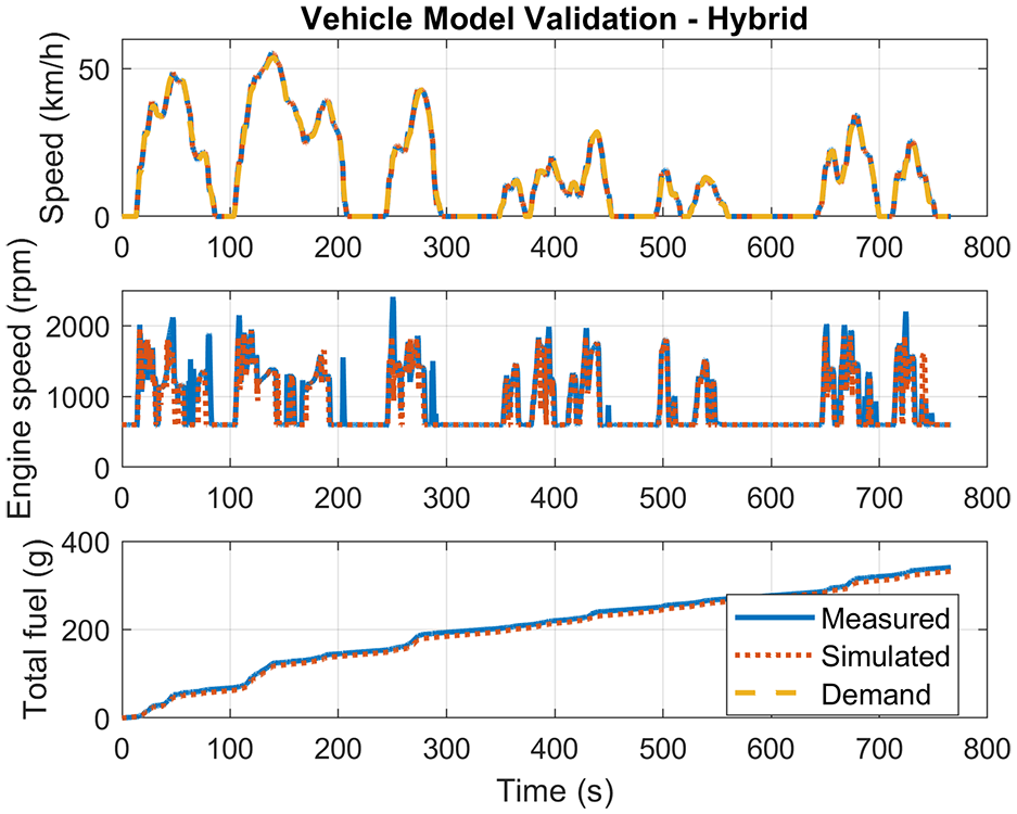
Validation of hybrid model.
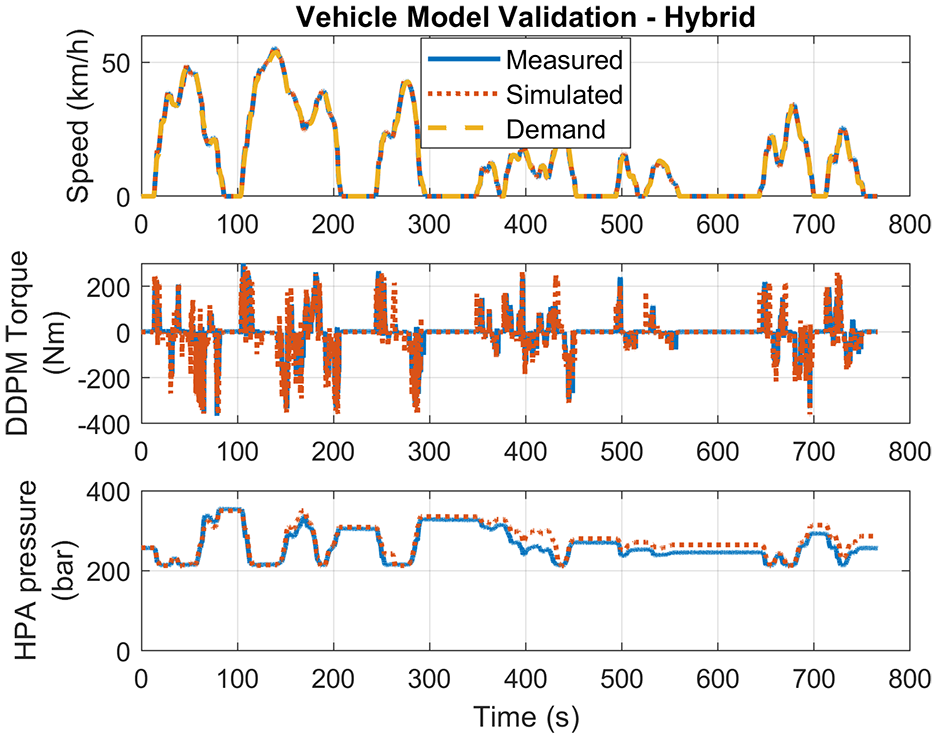
Validation of hybrid model – hydraulic system.
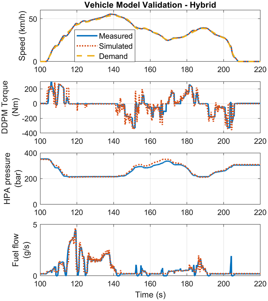
Closeup of stop-start section of hydraulic model validation.
Figure 14 shows the fuel consumption of the model after the improvements, as compared to the test results. The fuel economy of the hybrid vehicle calculated from the simulation was 7.63 km.l-1, over-estimating by 2.1% compared to the measured 7.47 km l−1. The modelled fuel economy improvement was therefore calculated to be 24.3%, which is 2.9% higher than the measured fuel economy improvement of 23.6%.
Figure 15 shows the performance of the model when comparing the hydraulic system behaviour. The total energy from the accumulator in simulation was 1.435 MJ compared to the measured 1.292 MJ, a 10% difference.
Evaluation of possible benefits
This section uses the model to investigate the benefits of hydraulic hybridisation if a more optimal system were used, or if the driving cycle were changed.
The JE05 midtown cycle
The validated model was modified to remove the fuel used for down-shifts and allow motoring with the engine de-clutched, as discussed above. The DDPM size was increased to 96 cm3 rev−1. Such an increase could be achieved simply by increasing the stroke of the hydraulic drive (i.e. increasing the eccentricity of the cams within the DDPM – see Figure 2), without impacting on the packaging space.
The PTO torque limit and maximum pressure were increased to 550 Nm and 420 bar respectively. With these modifications, the optimal accumulator pre-charge was found to be 250 bar, resulting in a fuel economy improvement of 43%, to 8.76 km l−1. The results from this modified simulation are shown in Figure 17.
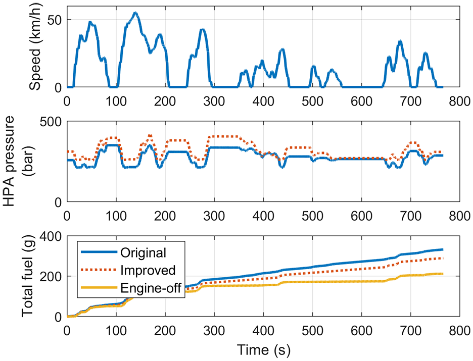
Results of increasing DDPM size and including engine stop-start on vehicle performance and fuel usage.
It was found that increasing the DDPM above 96 cm3 rev−1, which would require a re-designed PTO with a higher torque limit and possible chassis re-design, yielded relatively small increases in fuel economy, so would likely be un-economical.
Figure 17 also includes a line showing the fuel consumption of the system if engine stop-start were implemented on the vehicle, which was not possible in previous DDPM hybridisations. 23 In this case, the engine is turned off when the vehicle is stopped, stopping the fuel consumption, and turned back on when the DDPM could no longer satisfy the acceleration demand. With this additional change, the fuel economy of the vehicle would be increased further, by 95.2% compared to the baseline vehicle, to 11.99 km l−1.
It would be possible to add further hydraulic accumulators, to increase the energy storage of the system. However, this begins to produce diminishing returns since most of the braking energy was captured by the 25 l accumulator and the additional weight of larger accumulators would reduce the carrying capacity of the vehicle.
The worldwide harmonised light vehicles test procedure (WLTP)
To determine the benefits of the system over a more widely used drive cycle, the model was run over the WLTP (class 3b) cycle commonly used for passenger cars and commercial vehicles. The light vehicle in this analysis has a maximum speed of 110 km h−1 and the limited power available made it impossible for the vehicle to follow the extra-high section of the WLTP. Therefore, as suggested in official guidance, the extra-high section of the WLTP was excluded from these analyses. 35
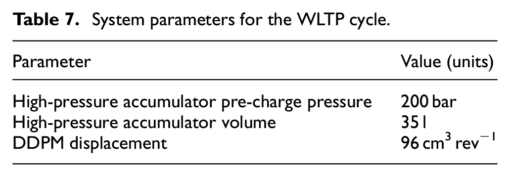
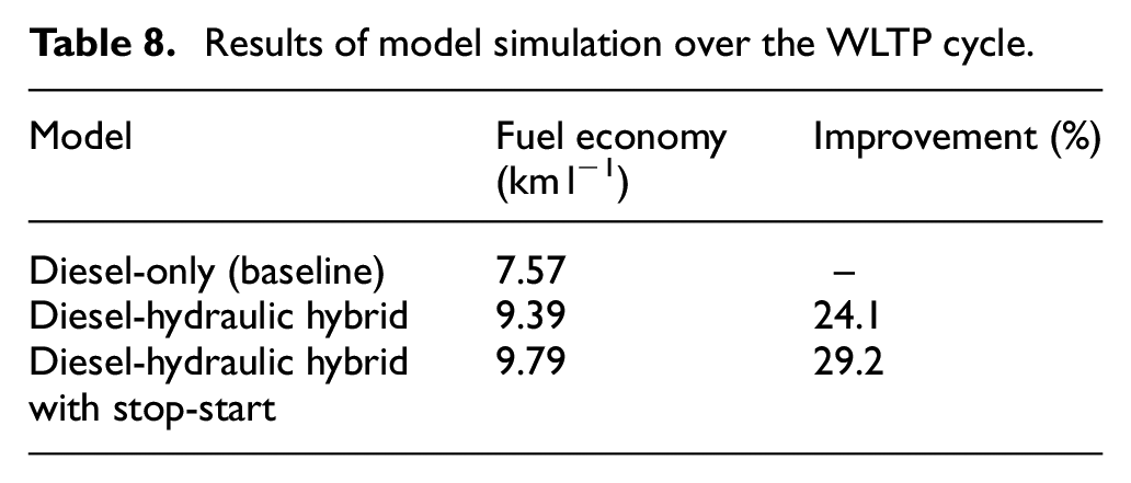
The 96 cm3 rev−1 DDPM was used and the accumulator pre-charge was re-optimised. The system parameters are given in Table 7, and the results from the simulation are given in Figure 18 and Table 8. These results show that the hybridisation can increase fuel economy by 24%, which can be further increased to 29.2% with engine stop-start.
System parameters for the WLTP cycle.
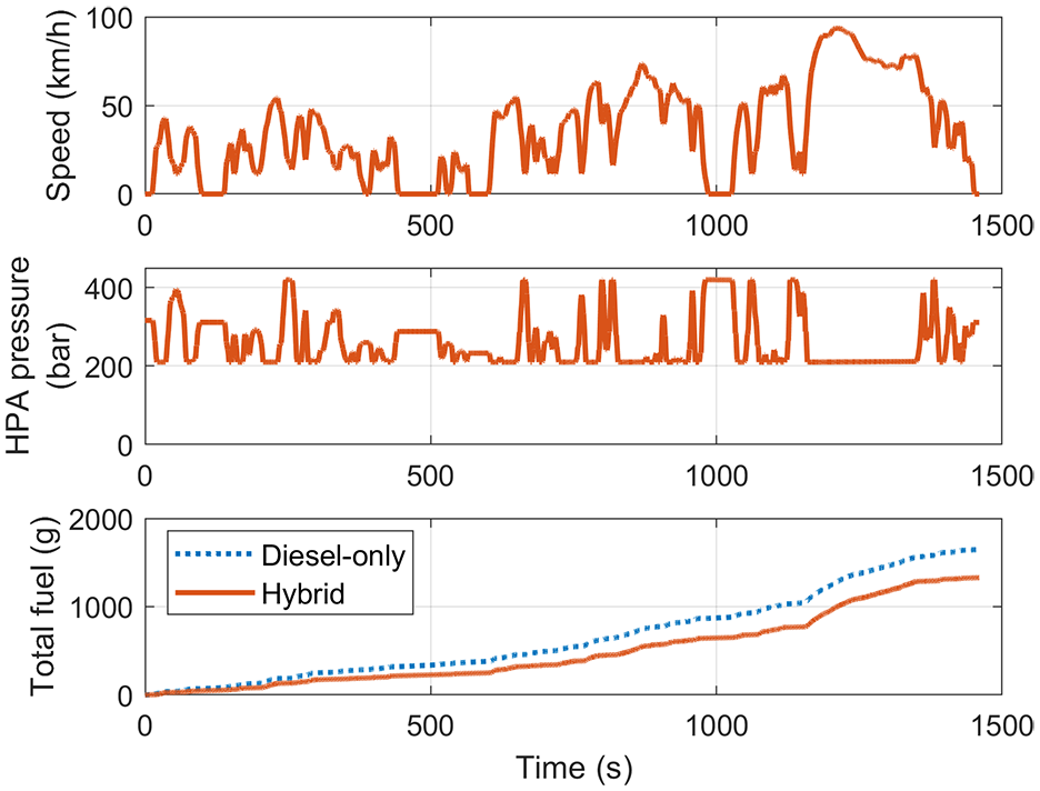
Modelled fuel consumption for the hybrid vehicle and the diesel engine only vehicle over the WLTP cycle.
Results of model simulation over the WLTP cycle.
Generalising the results
Previous studies have shown that the DDP is 20%–50% more efficient than a swashplate pump 19 and it is expected that a DDPM would show similar efficiency gains when compared to a swashplate pump/motor. This has two implications for parallel hydraulic hybridisation. Firstly, that efficiency gains could be made in existing hydraulic hybrid vehicles if the existing hardware were replaced with DDPMs. Furthermore, if the DDPM in this vehicle were replaced with a swashplate pump/motor it would reduce the fuel economy improvement by approximately 30%–75% due to the additional energy lost during the wheel-accumulator-wheel round trip. However, as previous studies have shown, there are still fuel usage reduction benefits from hydraulic hybridisation with these less efficient technologies.
The model developed in this study is modular in nature, allowing components to be swapped out easily. For example, it is possible to replace the DDPM model with a similarly detailed loss model of a swashplate pump/motor if one were available.
Other sources of energy saving
Light goods vehicles, such as the one under consideration in this study, often have additional hydraulic equipment such as refuse compactors and lift functions. The presence of the hydraulic hybrid system presents an attractive opportunity to integrate this equipment with the hybrid system to further improve the fuel savings. Recent tests at Danfoss using a DDPM with a loaded linear actuator have shown that between 78%-88% of the energy originating from the prime mover can be recovered. 36
Conclusions
This paper has reported for the first time the analysis of a novel hydraulic hybrid light truck that uses a Digital Displacement® pump/motor (DDPM). The new model was validated against test data and was used to determine the benefits of hydraulic hybridisation over a Japanese urban cycle (JE05 midtown) and the WLTP cycle, showing significant fuel economy improvements over both cycles.
The significant conclusions for this work are as follows:
A light goods vehicle has been successfully converted to a hydraulic hybrid vehicle using a DDPM;
In testing, the hybridisation increased the fuel economy of the vehicle by 23.5% over the JE05 midtown cycle;
A validated model was created, which matches the tested vehicle’s fuel consumption to within 2.1%;
When the vehicle model was optimised, and engine stop-start was included, the hybrid system increased the fuel economy of the vehicle by 95.2% over the JE05 cycle and by 29.2% over the WLTP cycle.
Hybridisation with hydraulic DDPMs is shown to be an effective way to increase the fuel economy of light trucks over urban-type drive cycles.
Footnotes
Acknowledgements
The authors would like to thank the staff at Danfoss for their help with the vehicle conversion and testing and the engineers of the truck manufacturer, with whom this project was a collaboration.
Declaration of conflicting interests
The author(s) declared no potential conflicts of interest with respect to the research, authorship, and/or publication of this article.
Funding
The author(s) received no financial support for the research, authorship, and/or publication of this article.