
Abstract
A novel integrated multi-physics assessment of the piston top compression ring of an internal combustion engine under normal operation mode, as well as subjected to cylinder deactivation is carried out. The methodology comprises ring-liner thermo-mixed hydrodynamics, elastodynamics of ring, as well as combustion gas blow-by and emissions. Therefore, the analysis provides prediction of ring-liner contact’s energy losses and gas power leakage across the piston and ring crevices, as well as the resulting emissions. Cylinder deactivation (CDA) technology reduces the unburnt fuel entering the ring-pack crevices, as well as the emissions. It is also shown that the frictional and gas leakage power losses are exacerbated under CDA by as much as 20%. Although this is much lower than the potential gains in fuel usage when using CDA. The optimisation of the piston compression ring would provide further fuel efficiency and improved emissions, an issue which has not hitherto received the attention which it deserves. The in-depth analysis has also shown that CDA reduces the predicted CO, NOx and HC emissions by nearly as much as 8.5%, 10% and 8.7%, respectively.
Introduction
Two desired requirements of modern internal combustion engines (ICE) are improved energy efficiency and reduced environmental pollution. These requirements are partly driven by the ever-stringent emission legislations,1,2 and partly sought to mitigate the dwindling reserves of fossil fuels3,4 as the transport sector aims for a sustainable future. 5 With 94% of the total energy demand for transport still provided by hydrocarbons, 6 countering all sources of energy loss from powertrain systems 7 has become critical in realising the aforementioned objectives. Richardson 8 provided a breakdown of ICE losses, showing that approximately 50%–60% of these are related to thermal inefficiency and 15%–20% result from parasitic frictional losses.
New engine technologies such as stop-start, cylinder deactivation, indicated gear shifting strategy and variable valve actuation are aimed at improving fuel consumption of the ICEs. Cylinder deactivation is a widely adopted energy saving technology, where some cylinders are deactivated when full engine power is not required, such as in congested traffic or in steady state highway cruising. In this manner significant energy savings and reduced emissions are achieved.9–12
The primary function of the top compression rings in engine cylinders is to tightly seal the piston and the cylinder wall, mitigating gas pressure leakage. Consequently, the requirement for a tight seal can in turn lead to increased friction. This results in significant contribution to engine parasitic losses, especially from such small components as the compression rings. Therefore, effective sealing to guard against gas pressure loss can paradoxically result in increased frictional losses. At the same time owing to its thinness and structural flexibility the compression ring is also subject to elastodynamic behaviour. This behaviour affects its primary sealing function as well as its conjunctional friction, leading to increased harmful gas emissions. These often very contradictory requirements mean that a complex analysis is required to optimise the piston compression ring, potentially providing significant benefits in energy efficiency 13 and emissions of the ICE. In fact, 3%–5% of the total ICE losses are associated with the piston compression ring-to-cylinder liner conjunction14,15 and at least 2%–7% of engine losses are attributed to gas pressure leakage. 16 Furthermore, the contribution of trapped unburnt fuel in the piston ring crevices due to gas blow-by is an important source of hydrocarbon emissions.12,16,17 Therefore, the dynamics and loss of sealing of a compression ring are root causes of hydrocarbon emissions with unburnt fuel entering its crevice volumes. Dealing with these complex issues can significantly reduce harmful emissions through optimal fuel usage and improved energy efficiency.
It is quite essential to accurately predict the tribological conditions in the piston ring-cylinder liner conjunction as a prelude for the determination of its frictional losses. Some early tribological studies were reported by Castleman 18 and Furuhama, 19 predicting lubricant film thickness in the piston compression ring-to-cylinder liner conjunction. Dowson et al. 20 also presented a 1D isothermal solution with assumed fully flooded inlet conditions. Later efforts included partial or mixed regimes of lubrication,21,22 including the more realistic inlet meniscus starvation.23,24
Based on the evaluation of Friction Mean Effective Pressure (FMEP), Akalin and Newaz 22 showed reasonable agreement between their numerical predictions and in-situ measured friction by Furuhama and Sasaki. 25 However, a more realistic analysis requires solution of 2D Reynolds equation, including assessment of conformability of the ring to the liner surface such as those conducted in Ma et al., 26 Mishra et al.,27,28 Fang et al., 29 and Rahmani et al. 30 The study by Rahmani et al. 30 showed that mixed regime of lubrication is dominant for most of the power stroke. Piao and Gulwadi 31 also included the out-of-round bore effect, friction and blow-by. An important aspect in such analyses is the conformance of the compression ring to the bore surface. This is affected by the elastodynamics of the compression ring, subjected to gas pressure, ring tension, and contact forces and friction between the ring and the liner, as well as with the ring’s retaining piston grooves. Rigid body dynamics of piston compression ring has been utilised to investigate gas flow, friction, dynamics and oil transport in the piston ring pack.32,33 These studies were later extended to include more realistic flexible elastodynamics of the compression ring in a series of studies for its in-plane (radial) and out-of-plane (axial and twist) motions.33–37 Ring dynamics is essential in the study of both gas blow-by and frictional performance; an approach recently highlighted by Turnbull et al.38,39 Therefore, an integrated solution of gas dynamics through the crevices formed by an elastic ring and piston retaining grooves, together with a 2D tribological contact of ring-bore is required.
Another important issue is the inclusion of 2D mixed thermo-hydrodynamics of ring-liner contact, where it has also been shown that the lubricant contact temperature is primarily governed by the liner temperature, which clearly determines the lubricant viscosity, prevalent regime of lubrication and friction. 40 Changes in liner wall temperature also influence the hydrocarbon (HC) and nitrogen oxide (NOx) emissions in an ICE. 41 It is well established that the unburnt fuel mixture, trapped in the piston crevices, comprises 4%–8% of the fuel mixture inside the cylinder, which is comparable with the total 3%–10% unburnt fuel mixture during a combustion cycle. Hence, the trapped fuel mixture in piston crevices is considered as a major source of hydrocarbon emissions.16,17
Hydrocarbon emissions are as the result of unburnt fuel within an internal combustion engine. The sources of hydrocarbon emissions are the formed crevices by the piston rings and their retaining piston lands/grooves and the head gasket, valve seats and spark plug threads. 17 Wang and Stone 41 investigated the effect of wall temperature on hydrocarbon and nitrous oxide emissions. It was demonstrated that hydrocarbon emissions decreased with rising wall temperature, because of a combination of higher combustion temperature, as well as the wall temperature. Wang and Stone 41 noted that especially under higher-load and higher-speed applications the nitrous oxide emissions increased with higher wall temperature. An increase in the liner wall temperature tends to reduce HC emissions and usually causes NOx to rise in high speed, high load applications. NOx emissions also vary with air-fuel ratio, combustion timing and duration.17,42 Rahmani et al. 43 noted that an optimum liner temperature would allow a certain trade-off between emissions and generated friction. Higher temperatures reduce lubricant ingression into the combustion chamber which in turn decreases the rate of lubricant evaporation, and hence the emissions. Reducing oil flow in this manner is increasingly important as lubricants can absorb and desorb hydrocarbons from fuels, 44 with adverse effects from some lubricant additives upon emissions. 45 This is because certain elements in the lubricant additive package, such as phosphorus, zinc, or sulphur can adversely affect the exhaust catalysts, which in turn reduces their efficiency, rising the emissions from the vehicle. In addition, these lubricant additives can cause formation of sulphates, downstream of a catalysed particulate filter or other oxidation catalysts. Furthermore, the importance of lubricant temperature and reducing lubricant warm up time on mechanical efficiency and CO emissions highlights the importance of a lubricant upon engine efficiency and emissions. 46
The foregoing discussions demonstrate the need for a comprehensive integrated ring elastodynamics, gas flow dynamics and ring-liner mixed thermo-hydrodynamics analysis to study the power losses and emissions of an engine under normal operating conditions. This is also important when a vehicle is subjected to the use of new technologies with an increasing uptake in modern vehicle fleet such as cylinder deactivation (CDA). This is the integrated approach undertaken in this paper, which extends the work recently reported by Morris et al., 47 which does not include the elastodynamics of compression ring and the associated gas blow-by. The current integrated study of ring elastodynamics and gas blow-by is original contributions and has not hitherto been reported in the literature, particularly with the inclusion of CDA.
Outline of methodology
Piston ring in-plane flexible dynamics
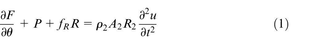
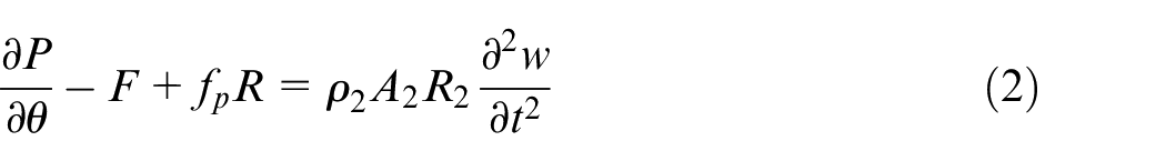
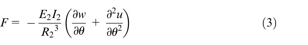
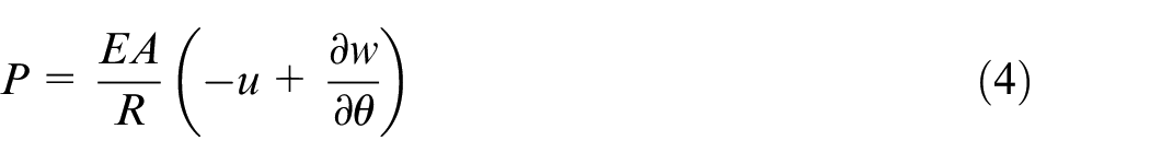
The coupled equations of motion for small deformations of a thin beam with negligible shearing deformation are given by 48 :
where,
where,
The in-plane dynamics equations (1) and (2) are discretised using central difference discretisation, based on the finite difference method (FDM). 38 The solution to the coupled in-plane elastodynamic equations of motion (1) and (2) can then be found based on either an analytical 35 or a numerical method. 38
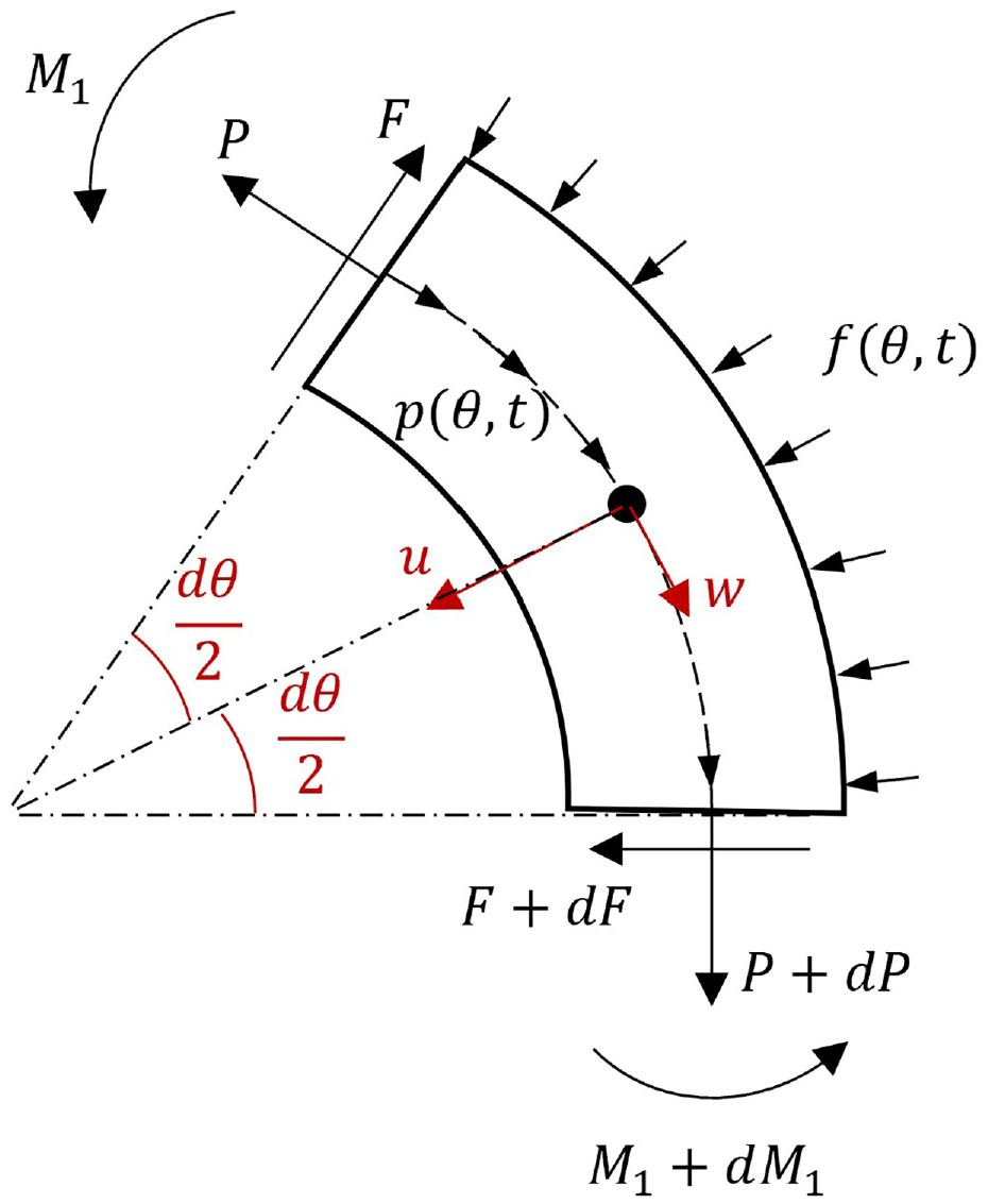
Forces and moments acting on an element of a ring.
Tribology of piston ring – cylinder liner contact
The piston compression ring-cylinder liner contact is subjected to mixed hydrodynamic regime of lubrication for much of the piston cycle. The viscous contact pressure,
where,

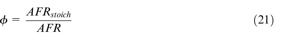
where,
Piston axial kinematics is used to approximate the sliding (axial) velocity,
The modified Dowson and Higginson relationship is used to account for the variation of lubricant density with generated contact pressure and temperature50,51:
The effect of pressure and temperature on lubricant viscosity is taken into account through the relationship first developed by Roeland 52 and later modified by Houpert 53 as:
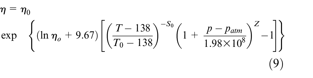
The reference viscosity,
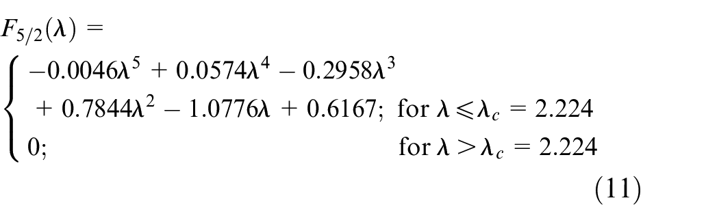
The contact load is carried partially by the viscous lubricant,
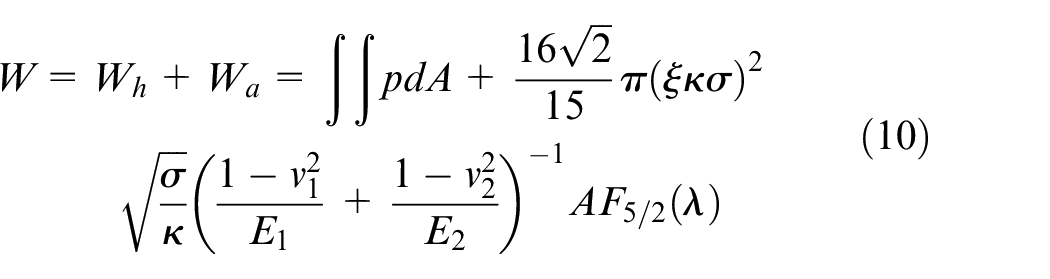
where,
The total friction takes into account viscous friction,
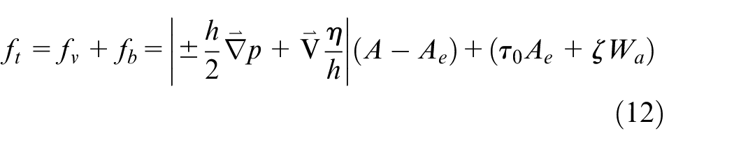
where,
Heat is generated within the contact due to friction. As a result, the contact temperature increases in addition to the surface temperature rise due to combustion. It is shown that under hot operating conditions, the contact temperature is usually dominated by the temperature of the cylinder liner 40 and the thermal effect of friction is relatively inappreciable.43,58 Therefore, in the current study it is assumed that the contact temperature is the same as the surface temperature of the cylinder liner.
Combustion gas blow-by and exhaust emissions
The combustion gases flow into and out of the piston-piston ring crevices during a typical engine cycle. Therefore, some engine power loss can be associated with the gas blow-by as is highlighted in Turnbull et al. 39 To evaluate the leakage power loss a gas control volume model needs to be utilised to predict the mass flows through these crevices as shown schematically in Figure 2.
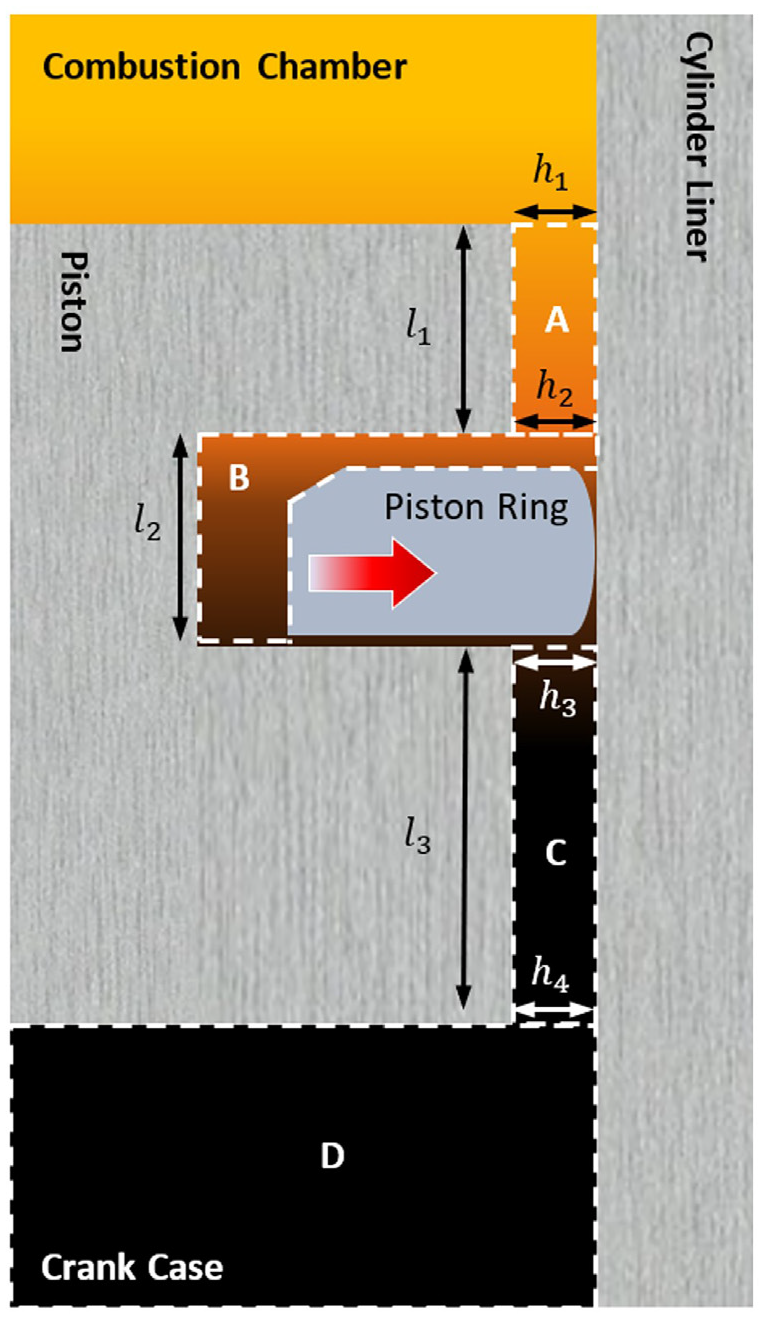
Schematic representation of the control volumes in piston crevices.
Several methods for gas blow-by have already been presented in the literature.16,39,59,60 The gas blow-by model used in the current study is that presented in Turnbull et al. 39 Therefore, the details are repeated here for the sake of brevity. The associated power loss is obtained as39,61:
The mass fraction of burnt fuel in the combustion chamber at a point during the engine cycle is determined 62 as:
where,
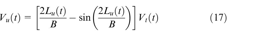
The volume of unburnt gas within the combustion chamber is 16 :
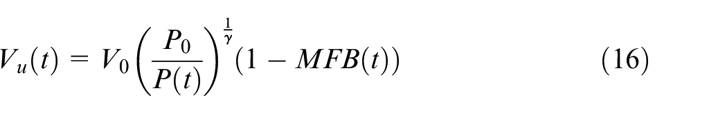
where,
A number of assumptions are made:
(1) There is steady mass flow rate per unit area into the piston crevices
(2) The mean flame front location is defined by the burnt mass fraction of the fuel
(3) The mean flame front can be approximated to a plane orthogonal to the piston crown surface
(4) The unburnt charge is compressed in an isentropic manner
With these simplifying but reasonable assumptions, a relationship can be found between the volume of unburnt fuel mix and the total swept cylinder volume as 16 :
where,
The unburnt mass flow rate into the crevice A (Figure 2) from the combustion chamber is therefore 16 :
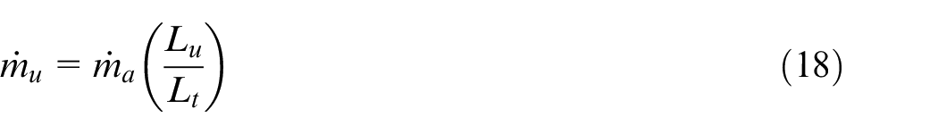
where,
The burnt portion of the mass flow rate into the crevice A from the combustion chamber is therefore: 13
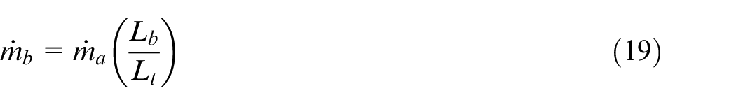
where,
Shayler et al. 17 developed relationships between the mass flow rate of the fuel and any pollutants for various types of automotive gasoline engines.
The ratio of CO mass flow rate to mass flow rate of fuel supplied
where,
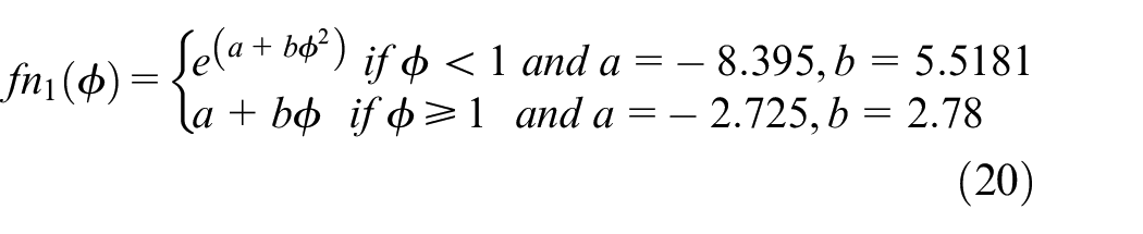
CO predictions are a primary function of the equivalence ratio and not the engine operating conditions.17,61 The index of CO emissions is determined as:

The HC emissions are related to the equivalence ratio as:
where,
The spark timing for the Minimum Advance for Best Torque Delivery (MBTD) is given for various exhaust gas recirculation (EGR) in Shayler et al. 17 for different engine types. The relationship between HC emissions and MBTD is:
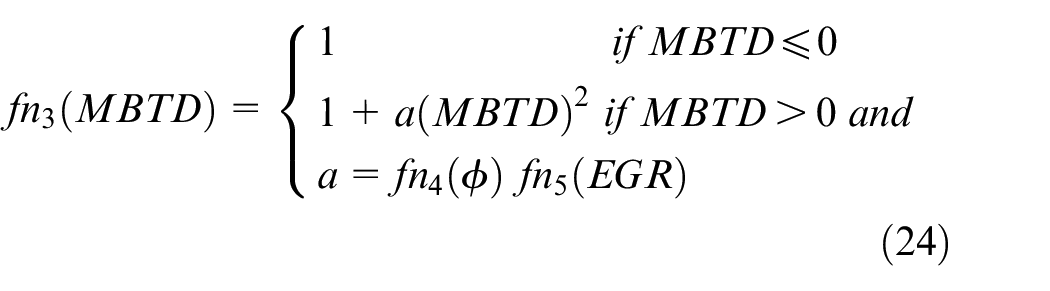
where,
The constants

where
HC emissions index is therefore determined as 17 :

where,
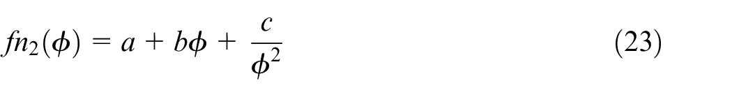
NOx emissions are related to the air/fuel ratio
where
NOx emissions are related to the spark ignition timing (MBTD) through:

where, the constants
NOx emissions index is therefore predicted as 17 :

Solution methodology
The integrated multi-physics model in the current study includes the flexible ring elastodynamics, mixed thermo-hydrodynamics of ring-liner contact and a gas blow-by model. The blow-by model is an expansion of that detailed in Turnbull et al. 39 to include predictions of unburnt and burnt fuel in the piston crevices, as well as exhaust gas emissions (Figure 3). The overall integrated multi-physics model is also used to study the effect of CDA.
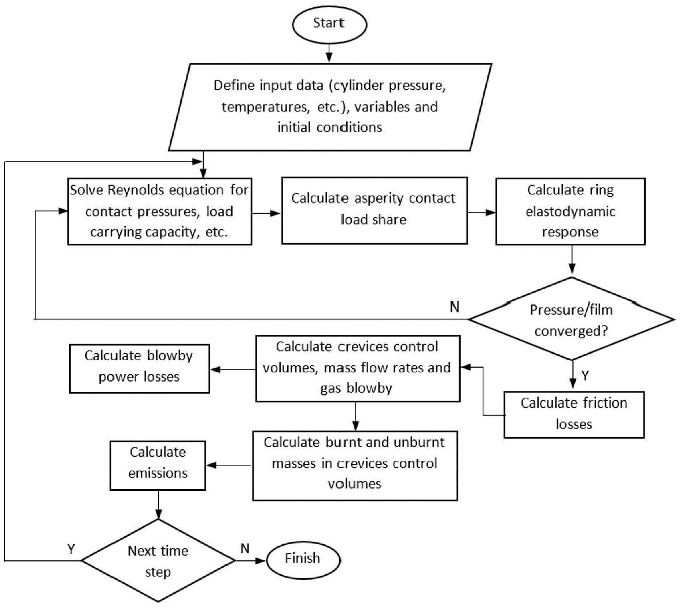
Computational flow chart.
The following solution procedure is used:
Step 1: Advance the crank angle, commencing from 0°
Step 2: Solve Reynolds equation and elastic film shape with rheological state equations for the ring-liner contact, determining pressure distribution and lubricant film thickness.
Step 3: Determine the hydrodynamic reaction and asperity load, thus the total contact load.
Step 4: With net applied forces, calculate ring deformation and velocity profiles
Step 5: Determine viscous and boundary friction, thus total friction and frictional power loss.
Step 6: Determine gas pressures in the control volumes as well as gas leakage
Step 7: Return to step 1.
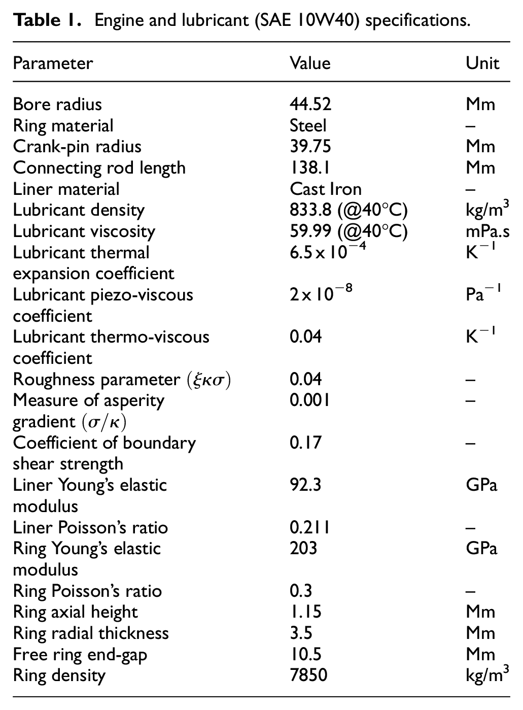
Engine specifications
The developed model comprises piston ring elastodynamics, tribology of contact between the ring and liner, and gas dynamics. Therefore, it is a multi-physics model. In addition, thermal effects are incorporated in both lubricant rheology and flow of blow-by gasses.
In the current study, measured liner temperature is used in the analysis, whilst the heat generated due to friction and its conduction and convection from the contact is neglected. It must be noted that the compressible gas flow through the crevices consumes a relatively small portion of expended fuel energy. This can result in an unburnt fuel mixture, which is a major source of hydrocarbon emissions. 16
A 4-cylinder, 4-stroke spark ignition engine is studied here. Engine specifications pertinent to the current analysis are listed in Table 1. Figure 4 shows the measured cylinder pressure and liner temperature for the three cases of (i)- a cylinder under normal engine operating condition, (ii)- an active cylinder under CDA and (iii)- a deactivated cylinder. Under normal engine operation all the four cylinders remain operational, whilst during cylinder deactivation two cylinders are active and the other two are deactivated. The deactivated cylinders have a closed inlet and exhaust valves, resulting in compression and expansion of the cylinder residual charge content. The active cylinders experience higher combustion pressures and cylinder wall temperatures to maintain the desired output power. The liner wall temperature is measured during steady state operating condition, where it is largely stable, with the main temperature variation noted between the top and bottom of the cylinder liner, rather than any transient variations between successive cycles.
Engine and lubricant (SAE 10W40) specifications.
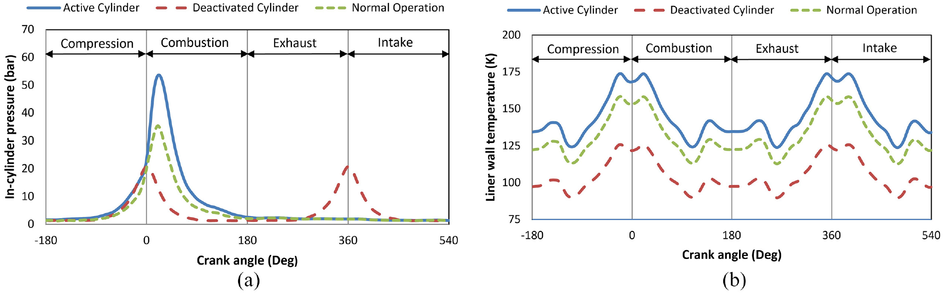
Measured engine data: (a) in-cylinder pressure, and (b) liner wall temperature at 3000 rpm and full load. 47
Results and discussions
Figure 5 shows the minimum lubricant film thickness variation for the piston compression ring-to-cylinder liner contact for an engine cycle. The film thickness for an active cylinder under CDA, a deactivated cylinder and a cylinder under normal engine operation are presented. The regime of lubrication falls into mixed and boundary conditions at the vicinity of Top Dead Centre (TDC) and Bottom Dead Centre (BDC) during piston reversals and during the power stroke owing to a reduced film thickness. There is a significant reduction in the film thickness for the active cylinder under CDA when compared with the cylinder under normal operation. This is because of the combination of a higher combustion pressure and liner temperature.
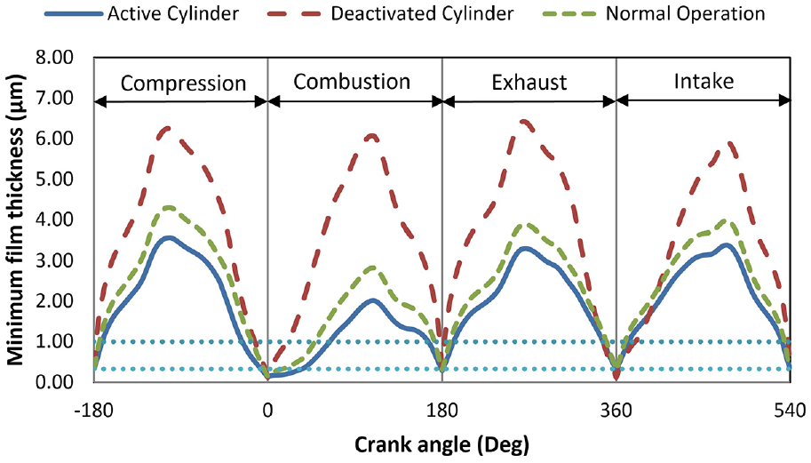
Compression ring-liner contact minimum film thickness variation in an engine cycle under different conditions.
The corresponding predicted friction under different cylinder operating conditions is shown in Figure 6. The reduction in film thickness for the active cylinder of the engine subjected to CDA promotes increased boundary friction well into the power stroke, whilst boundary friction under normal engine operating condition is significantly reduced. The deactivated cylinder has the most boundary friction at the TDC, which is rapidly decreased with an increasing sliding velocity, promoting an increased rate of lubricant entrainment into the contact conjunction. High boundary friction occurs because the combustion pressure within the deactivated cylinder at TDC (Figure 4(a)) is higher than for both the active cylinder of a CDA engine and the cylinder under normal engine operating mode. The combination of the increased boundary friction in an active cylinder of CDA engine and the increased boundary friction at the TDC for deactivated cylinders demonstrates the potential for higher wear in cylinder operating under CDA due to a severely reduced lubricant film thickness. This would required further investigations.
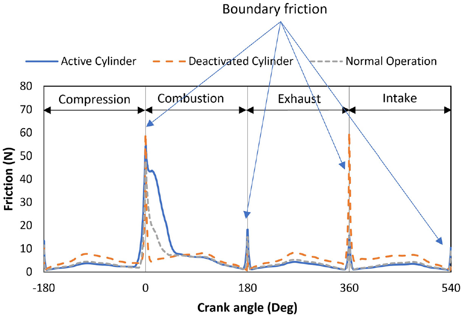
Predicted cyclic ring-liner friction in an engine cycle under different running conditions.
The corresponding frictional power losses are shown in Figure 7(a). There are significant power losses during the combustion stroke for an active cylinder due to prevalent boundary and mixed lubrication conditions. The power loss predictions for an active cylinder of a CDA operated engine are low during the remaining engine strokes because of a higher liner temperature, reducing the lubricant viscosity thus viscous frictional losses. On the other hand, there is significant viscous friction for the deactivated cylinder throughout the engine cycle due to its lower liner temperature, thus a higher lubricant viscosity. This finding supports the work reported by Di Battista and Cipollone 46 who outlined the importance of lubricant temperature upon frictional losses. Under normal engine operation mode there is high friction during the power stroke and a sizeable contribution by viscous friction for the remaining engine strokes. Unbalanced cooling is often seen as a drawback for engines operating under CDA. The results here demonstrate that this is the case in frictional predictions, with the lower liner temperatures increasing the viscous frictional losses for the deactivated cylinder. For the active cylinder with higher liner temperature boundary friction increases. Figure 7(b) shows the difference in cyclic friction for an engine operating normally and one operating under cylinder deactivation, which is similar to the results reported in the literature. 47
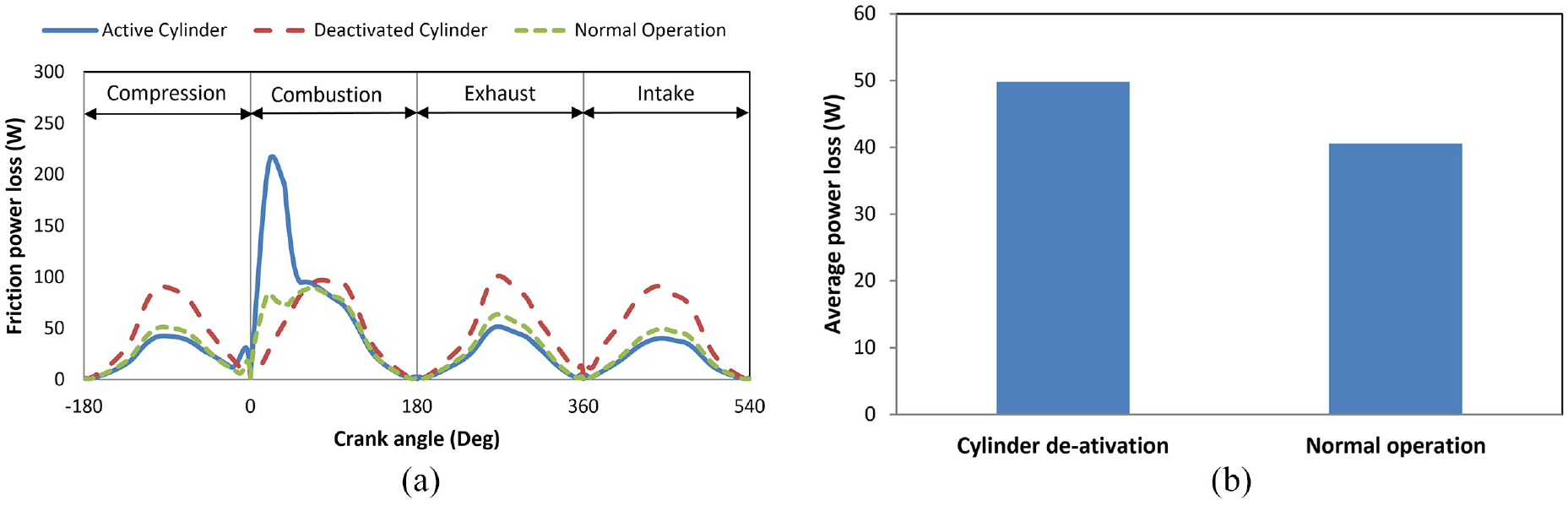
Frictional power loss predictions of ring-liner contact under different cylinder operating conditions: (a) per crank angle, and (b) average per cycle.
Power loss due to gas leakage in the form of blow-by through the piston ring crevices is shown in Figure 8(a). These are the highest for an active cylinder under CDA because of the higher operating combustion pressures. The deactivated cylinder also has high gas leakage power losses due to the cylinder compressing the gasses twice during an engine cycle. Figure 8(b) shows an increase in gas leakage losses per cycle for an engine operating under CDA. Namazian et al. 16 observed that piston ring crevice gas flow power loss can be at least 2%–7% of fuel energy, depending on the engine type. Gas power losses are likely to rise exponentially with any significant ring flutter. The current model does not include other rings within the ring-pack assembly. Therefore, it is likely that the gas pressure losses are somewhat over-predicted. Namazian and Heywood 16 showed that less than 20% of the unburnt fuel mixture mass is blown into piston compression ring crevices, reaching the crevices of the second ring. Hence, it is anticipated that emissions are mainly affected by the behaviour of the top compression ring.
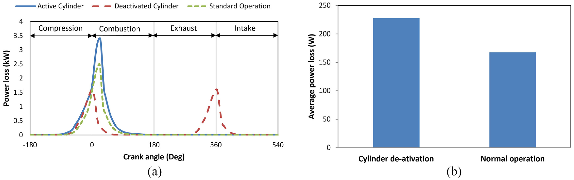
Gas leakage power loss predictions in an engine cycle under normal operation and cylinder deactivation: (a) per crank angle, and (b) average per cycle.
The total compression ring losses due to friction and gas leakage for the engine operating normally and under cylinder deactivation are shown in Figure 9. There is an increase of approximately 60.3 W per cycle under cylinder deactivation, representing an increase in losses of around 21.7%. This represents a significant increase in losses per cycle. However, these losses are small in comparison to the gains in fuel economy due to an engine operating under CDA.9–11 However, these losses are not often taken into account in assessing engine performance as they should be under CDA.
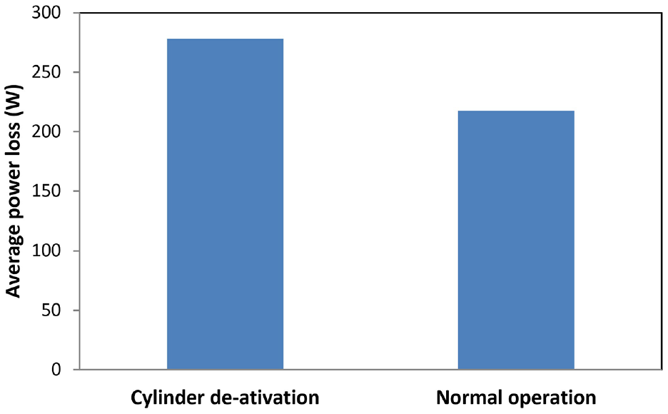
Average combined frictional and gas leakage power losses for an engine operating normally and subject to CDA.
Emissions
The total mass flow rate of unburnt fuel and burnt gas from the combustion chamber into the piston ring-pack crevices in the current predictive analysis is shown in Figure 10. The total unburnt fuel flow rate into the piston ring-pack assembly is significantly reduced under CDA as one would expect. The results show that combination of the higher cylinder wall temperature, a reduction in total fuel burnt and a decrease in unburnt fuel gas flow rate constitute a reduction in hydrocarbon emissions from the piston crevices for an engine operating under CDA.
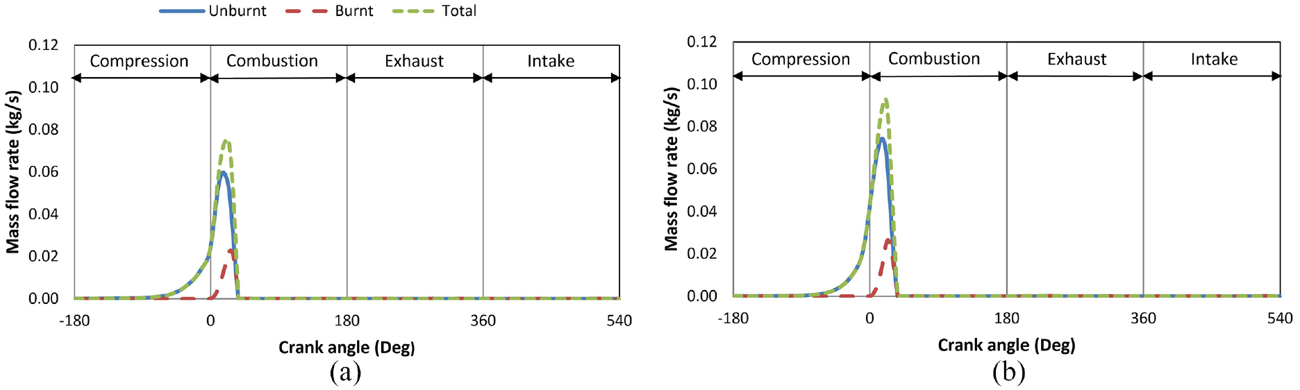
Total burnt and unburnt gas leakage from the combustion chamber into the piston ring-pack top crevice volume in an engine with: (a) CDA, and (b) normal operation.
Figure 10 shows that most of the gas flow into the piston crevices contains unburnt fuel. Absorption and desorption of unburnt fuel into the lubricating oil can contribute to emissions, 65 as well as lubricant contamination. 66 During excessive ring flutter, it is likely that there would be an increase in the gas flowing through the piston compression ring into the crank case. The simple analytical method expounded here to approximate the unburnt and burnt gases flowing through the ring pack provides a convenient and efficient analysis approach without the need for a more cumbersome computational fluid dynamics (CFD) simulations approach.
During operation an engine utilises a feedback loop to ensure that the air-fuel mixture is close to stoichiometric condition. The engine analysed in the current study acts under a constant full load condition, thus not reacting to any load transience. 47 Therefore, it can be considered to be operating around the stoichiometric air-fuel ratio. Under these conditions, Figure 11 shows that CO, HC and NO exhaust emissions are reduced when the engine is subject to CDA, similar to observations reported in.9,11 The reduction in predicted hydrocarbon emissions with CDA is in correlates with the reduction in blow-by gases as the major contributing source16,17 as shown in Figure 10. This trend is demonstrated in Figure 12 outlining the importance of unburnt fuel flow into the ring-pack crevices upon hydrocarbon emissions.
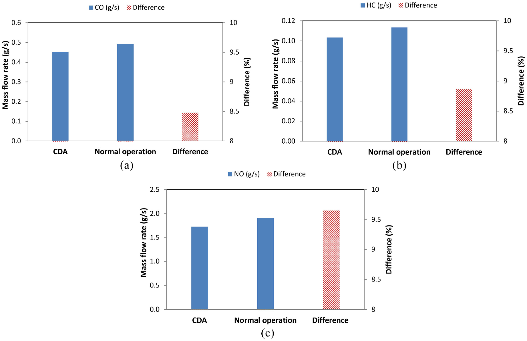
Predicted emissions for an engine under normal operation and an engine with CDA: (a) CO, (b) HC and (c) NO.
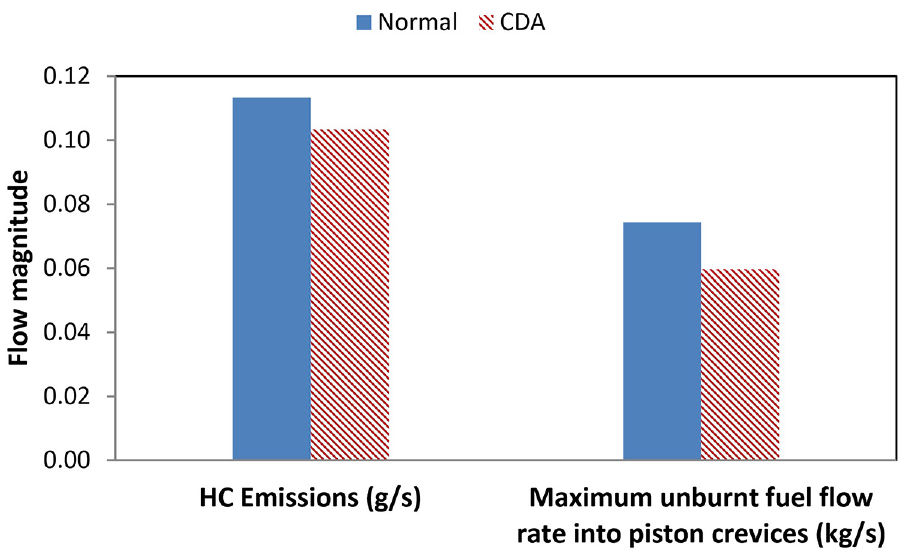
Trend demonstrating the reduction in predicted HC emissions and the maximum unburnt fuel flow into the piston ring-pack crevices.
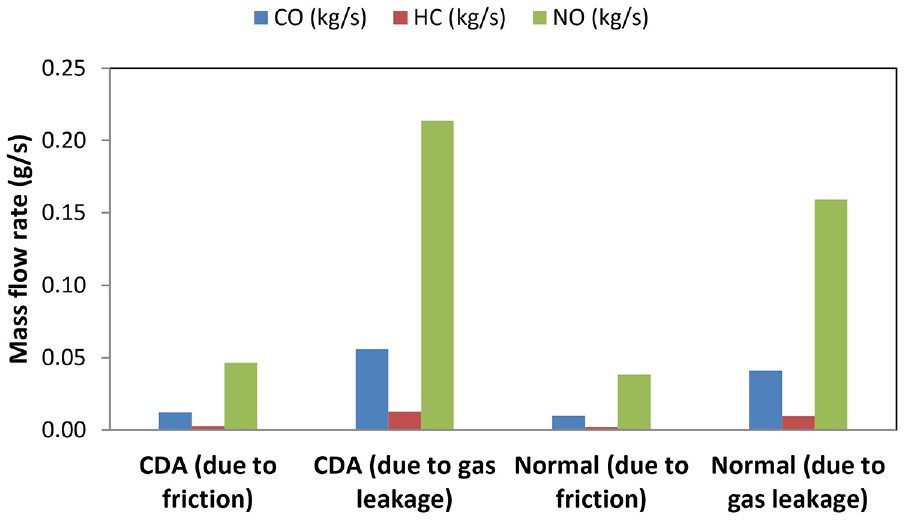
Emissions can be reduced by optimising the fuel usage. One way of achieving this is to mitigate frictional and gas leakage losses. A breakdown for the gas flow rate emissions due to the stated losses is presented in Figure 13. Although the total emissions have decreased for an engine operating under CDA, the emissions due to friction and gas leakage have actually increased. This demonstrates the importance of taking into account the frictional losses and gas pressure leakage together for modern engines using CDA, an approach has not been reported in the open literature yet. To reduce emissions, it is important that the piston compression ring effectively seals the combustion chamber. This can reduce blow-by through the ring-pack and consequently the emissions, as well as the hydrocarbon emissions attributed to the flow of unburnt fuel mixture entering the ring-pack due to gas blow-by.16,17 However, a good ring seal can increase frictional losses. Therefore, a careful trade-off between these contradictory requirements across the engine operating conditions needs to be achieved.
Breakdown of total emissions’ flow rate due to friction and gas leakage.
Concluding remarks
The analysis demonstrates that the piston top compression ring of active cylinders under CDA operates in mixed regime of lubrication in the vicinity of the piston reversal for longer than when operating under normal mode of engine operation during the transition from the compression to the power stroke and much of the latter. For the case of deactivated cylinders, hydrodynamic lubrication regime seems to be more dominant apart from vicinity of piston reversals, especially at the top dead centre where the cylinder pressure is the highest. The gas flow into the crevice regions of the compression ring-to-its piston retaining lands ensures that pressure behind the inner rim of the ring builds up conforming it to the liner surface as an effective seal, but it increases contact friction. The deactivated cylinders exhibit the highest boundary friction at the TDC to the higher build-up in pressure behind the ring, demonstrating the importance of an integrated multi-physics analysis such as the one reported in this paper.
Gas pressure leakage losses are highest for an engine operating under CDA because of the high combustion pressures. The deactivated cylinders act as gas springs with higher gas pressure losses as the piston moves from BDC to TDC than from TDC to BDC. It is shown that cylinder deactivation can increase the gas leakage and frictional losses by approximately 20%. This is much less than the gain in fuel savings due to reduced fuel use and pumping. However, reducing frictional and gas leakage losses is important in meeting targeted emission levels and improving fuel in modern engines especially that utilising cylinder deactivation technology.
The in-depth analysis has also shown that CDA reduces the predicted CO emissions by as much as 8.5%, the NOx emissions by nearly 10% and HC emissions also by 8.7%. Piston crevices are a source of HC emissions and an engine operating using cylinder deactivation technology reduces the amount of unburnt fuel entering the piston crevices due to gas blow-by. Therefore, the trend in reduced HC emissions is observed in the predicted unburnt fuel entering the piston crevices. Optimisation of the piston compression ring has a significant potential in reducing emissions. Objectives of reduced energy and subsequent emissions can be partially achieved through use of novel coatings on piston rings and/or cylinder liners as demonstrated in Dolatabadi et al. 67 and this can be considered as an extension of the current analysis using the methodology provided in the current study. Some numerical analyses have shown that use of textured features in piston ring-cylinder liner contact can improving the lubrication regime, thus reducing the frictional power losses, particularly during the engine warm-up.68,69 Therefore, a holistic approach seems to be the way forward in targeting the reduction of energy losses and emissions from engine components such as the piston rings.
Footnotes
Appendix
Abbreviations
| 1D/2D | One/Two-dimensional |
| AFM | Atomic force microscope |
| AFR | Air fuel ratio |
| BDC | Bottom dead centre |
| CDA | Cylinder de-activation |
| CFD | Computational fluid dynamics |
| FDM | Finite difference method |
| FMEP | Friction mean effective pressure |
| GFR | Gas fuel ratio |
| HC | Hydrocarbon |
| ICE | Internal combustion engine |
| LFM | Lateral force microscopy |
| MBTD | The minimum spark advance for the best torque delivery |
| MFB | Mass fraction burnt |
| NOx | Nitrogen oxides |
| TDC | Top dead centre |
Acknowledgements
The authors would like to express their gratitude for the financial support of the Engineering and Physical Sciences Research Council (EPSRC) under the Encyclopaedic Program grant (EP/G012334/1) and EPSRC-funded Doctoral Centre for Training (EP/L014998/1) in Embedded Intelligence (CDT-EI).
Declaration of conflicting interests
The author(s) declared no potential conflicts of interest with respect to the research, authorship, and/or publication of this article.
Funding
The author(s) disclosed receipt of the following financial support for the research, authorship, and/or publication of this article: This work received financial support from the Engineering and Physical Sciences Research Council (EPSRC grant numbers EP/G012334/1 and EP/L014998/1).