
Abstract
Piston skirt to cylinder liner conjunctions are amongst the major contributors to frictional power losses of Internal Combustion Engines (ICEs). Efforts have been made to mitigate the frictional losses of these conjunctions by incorporating different technologies such as texturing and application of novel coatings. Any potential technology needs to provide adequate wear resistance as well as frictional reduction in order to be practically applicable. In this paper, the piston skirt of a gasoline engine is deposited by three different variants of Graphene Oxide (GO) coatings deposited using an Electro-Phoretic Deposition (EPD) method. Their tribological performance is benchmarked against uncoated steel and graphite coated aluminium skirts. These coatings are experimentally characterised in terms of asperity level friction, topography and wear resistance. The conjunction and system level performance of these coatings considering both boundary and viscous friction and system dynamics are then evaluated using a multi-physics tribo-dynamic model. Results show that by incorporating an appropriate GO coating, the frictional power loss of the piston skirt to cylinder liner conjunction can be improved by up to 14% whilst maintaining the wear resistance of the coating at the level of an uncoated steel surface.
Keywords
Introduction
One of the key objectives in designing components and surfaces for automotive applications is to minimise frictional losses and maximise durability of the designed conjunctions. This process is driven not only by the desire to produce more fuel-efficient engines, but also by global regulations and directives put in place to tackle the harmful environmental effects of automotive emissions. 1
Within the ICE of passenger vehicles, it is reported that frictional losses across various contacts are responsible for around 20% of the total losses. The piston ring–cylinder liner and piston skirt–cylinder liner conjunctions contribute to more than 40% of these frictional losses as presented and discussed by Tung and and McMillan 2 In their overview of automotive tribology, Fitzsimons 3 and Holmberg et al. in their analysis of the global energy consumption due to friction directly related to passenger cars. 4 Demas et al. 5 investigated the piston-skirt conjunction under specifically highlighted boundary conditions.
In response to this, modern research surrounding engine and vehicle efficiency improvements focus on reducing these losses, such as the one presented in the work of Morris et al. 6 in which they focus on the optimisation of the piston compression ring for high-performance race engines, and Bewsher et al. 7 in which the cylinder liner is examined using AFM as a way to predict boundary friction at the piston ring to cylinder liner conjunction in more realistic manner, to better control the system’s efficiency. 7 Usman and Park. 8 proposed surface texturing as practical way to enhance the system’s frictional efficiency.
In addition to these current areas of research, the cylinder liner is also examined, such as in the work by Howell-Smith et al. 9 in which a combination of surface texturing and lubricating coating was applied to reduce the frictional losses within the ICE. 9 Similarly, Li et al. 10 reported on the wear behaviour of a cylinder liner prepared by laser finishing concluding that the tribological performance of the liner was improved compared to an un-treated liner.
Material selection for modern pistons tends to favour aluminium-based alloys primarily for their low weight and high thermal conductivity, preventing the piston crown from overheating. 11 Alternatively, pistons are manufactured from steel-based alloys with a compact design.
These frictional losses observed across conjunctions within the ICE may be palliated and controlled with the application of the appropriate lubricant, additive packages and thin solid film lubricants as coatings. The latter has been shown to demonstrate promising tribological improvements between sliding contacts where liquid lubrication alone may otherwise present challenges.12,13
Looking to the piston skirt–cylinder liner conjunction, it is commonplace to consider some manner of thin solid film coating to be applied to the piston skirt,11,14,15 as opposed to the cylinder liner. The effect of surface texture is also found to influence the tribological performance within the engine block. 16 Numerous investigations have been focused on applying texturing to the ring-pack, such as can be seen in the works of Etsion and Sher, 17 Ryk and Etsion, 18 Kligerman et al., 19 Pawlus et al., 20 Pandey et al. 21 and Grabon et al., 22 who all demonstrate the tribological improvement of applying surface texturing, typically through laser texturing, to the piston rings of an ICE.17–22 Limited research has been conducted on the tribology of the piston skirt–cylinder liner conjunction by comparison, and the research that does exist tends to focus on the effects of surface texture of the piston skirt 23 rather than the effect of an applied coating, such as those examined in this research.
Graphene, and similar forms of sp2-bonded carbon, have been the subject of research in many applications, ranging from within the ICE wherein graphene and graphene-based lubricant additives are tribologically assessed, such as in the works of Ramón-Raygoza et al., 24 Lin et al. 25 and Eswaraiah et al. 26 to applications in micro electro-mechanical systems (MEMS). 27 One such derivative is graphene oxide (GO). GO possesses similar mechanical and tribological properties to graphene and is a candidate for large scale production via soft chemistry synthesis approaches. 28 In addition to this, GO has already been shown to perform well in terms of its tribological performance as a thin film, as shown by Liang et al. 27 in which GO deposited by EPD showed good frictional and wear performance on silicon substrates, and by Berman et al. 29 in which the friction of multilayer graphene sheets could be effectively controlled by altering the oxidation of the film to form GO films. These observations highlight the attractive potential of GO as an industrial tribological coating.
Deposition methods for graphene-based tribological films in prior research tend to feature ‘laboratory-scale’ of methods such as chemical vapour deposition (CVD) and physical vapour deposition (PVD) 30 which pose challenges for upscaling of these coatings to industrial applications. In the current research, coatings are deposited by electro-phoretic deposition (EPD); a simple electro-plating method that is capable of depositing uniformly on relatively complex geometries and is more attractive as a disposition method for industrial applications than CVD or PVD, as these methods involve either a high cost of equipment, a deposition environment that is challenging to achieve, or both. It can also be seen from previous work that the topography, thickness and tribological characteristics of deposited coatings can be easily influenced by altering some of the parameters of the process.31–33 It is clear that EPD has advantages over CVD/PVD methods for deposition of nanostructured films. These include a simpler equipment and set-up, the fact that depositions can be applied at ambient conditions to avoid thermal distortion and ability to coat curved and complex surfaces such as piston skirt and gear tooth flanks.
Through accurate modelling and simulation of the piston skirt–cylinder liner contact under realistic operating conditions, the tribological impact of coatings may be assessed without the need for engine level experiment. Building computational models of sufficient accuracy is a key step in the development, design and optimisation process of the many components in a modern ICE including the engineered surfaces and coatings. Previous works involving modelling and simulation of contacts within the internal combustion engine have again favoured the piston ring–cylinder liner conjunction, as can be seen in the works of Li et al. 34 Zabala et al. 35 in which the friction and wear of the piston ring to cylinder liner conjunction is studied through experiment and numerical modelling, and in the work of Profito et al. 36 in which the effect of laser-textured micro-grooved piston ring surfaces are again studied through a combination of transient experimental and numerical modelling. There is limited research with regard to modelling the effect of tribological coatings on the piston skirt, however.37–39 Numerical models may seek to simplify certain parameters of real-world operation, to lower computation time and offer performance at idealised conditions. For simulating the tribology of the contact between two real engineering surfaces however, such as the piston skirt–cylinder liner conjunction, a multi-physics and multi-scale numerical approach is required. Such an approach should consider the interaction between the asperities of both surfaces leading to boundary friction, fluid film lubrication as well as micro and macro scale engine dynamics.
An approach for boundary lubrication analysis is presented in the works of Greenwood and Tripp,40,41 wherein two rough surfaces in contact are assumed to have a Gaussian distribution of peak heights of asperities. This can be supplemented by measured metrological data of real surfaces that may not possess this idealised distribution. This Greenwood and Tripp model has been used to simulate real contact in many applications including conjunctions within the modern ICE such as the piston ring-piston liner conjunction.42,43 One key input for this approach is the boundary shear strength of asperities,
In this work, the effect of GO coatings on tribological enhancement of piston skirt–cylinder liner conjunction in a single cylinder engine is investigated. Three GO coatings are deposited by EPD method on steel substrates as candidates and are benchmarked against a commercial graphite coating as well as uncoated steel. The GO coatings provide a wide range of topographical and morphological characteristics, obtained by altering coating conditions. The morphology of coatings is characterised using Scanning Electron Microscope (SEM), the topographies are measured using optical microscopy methods, shear strength of asperities are obtained by AFM in LFM mode and the wear resistance of coatings are investigated using scratch test by AFM. This surface level data is then used to inform a tribo-dynamic model of a single cylinder engine with coated piston skirt. The tribological performance of the three coatings is simulated alongside the commercial graphite coating and the uncoated piston, considering both boundary and viscous lubrications. In addition to this, results demonstrate the effective friction reduction and wear enhancement capabilities of GO coatings over a commercial graphite coating applied to the piston-skirt.
Such a study, fabricating, characterising and investigating GO as a potential and practical coating for tribological enhancement of piston-skirt conjunction, and presenting this multi-scale approach has not been reported hitherto.
Methodology
In this section, the method of GO production, deposition of coatings, characterisation of the surface as well as modelling approach are presented.
GO production
GO for deposition is synthesised using a modified Hummer’s method,31,47 as is typical for research such as this. 48 The resulting ‘GO slurry’ then undergoes high-speed centrifuging multiple times as part of a multi-step cleaning process with diluted hydrochloric acid (10% concentration HCl) and de-ionised water (H2O). The cleaned GO is subject to a low temperature oven (75°C) to dry in air over a period of 12 hours. Graphite (C), sulphuric acid (H2SO4), sodium nitrate (NaNO3), potassium permanganate (KMnO4) and hydrogen peroxide (H2O2) used in this method are all obtained from commercial sources. The final product is obtained in form of compost-like structures. Figure 1 shows the SEM image of GO after production stage.
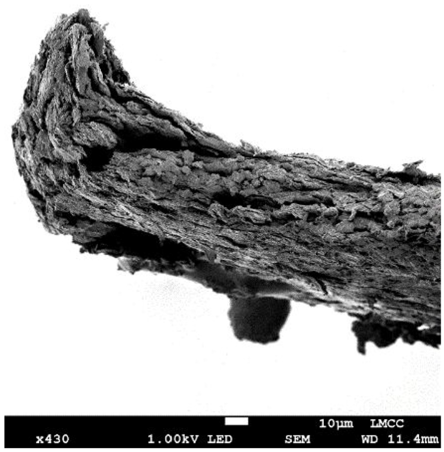
SEM electron micrographs of GO after production.
GO coating deposition
EPD is the chosen method of depositing the GO coatings. Three coatings are deposited, which are henceforth referred to as coating candidates 1, 2 and 3. Dispositions are achieved using a simple electroplating ‘bath’ designed and manufactured for this purpose, and a platinum foil electrode controlled via a Metrohm PGSTAT204 potentiostat. The separation distance between the substrate and the platinum electrode is maintained at a constant 40 mm. A simple schematic of the deposition equipment is presented below in Figure 2. The substrate material is AISI 8620 alloy steel. Cylinders of depth 4 mm and diameter 8 mm were manufactured and underwent sand blasting on the coating surface to remove undesired surface texturing from machining processes.
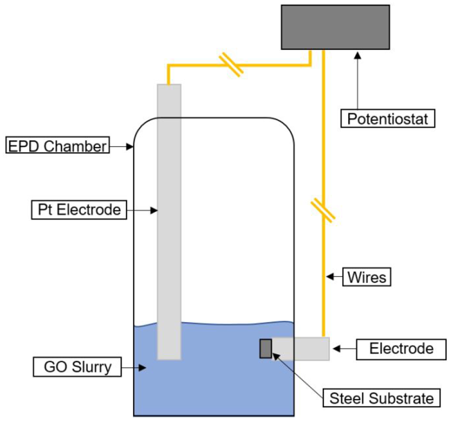
Schematic of EPD equipment.
Analysis of GO coatings
All coating candidates are analysed using methods detailed below to gather data to either inform the computational model or provide an indication of why certain tribological behaviour is or is not observed during the data analysis stage.
Topographical and morphological assessment of coatings
A scanning electron microscope (SEM) is used to examine the morphological structure of GO before and after deposition. This is achieved with a JEOL 7100 FEGSEM using an accelerating voltage of 10 kV for the GO coatings and 1 kV for the uncoated GO.
Information about the topographical aspects of the coatings was obtained using an Alicona InfiniteFocus 3D optical profiler. The vertical resolution of the system is 0.15 nm, the lateral resolution is 2.9 µm, and an objective magnification of ×20 is used. The surfaces are characterised by surface roughness (Sq), peak density (Spd) and peak curvature (Spc), based on the international standard ISO 25178-2. 49 The peak height distributions of the deposited films are also reported to demonstrate their distributions which is used to determine if additional contact modules are required to be used in the simulation of the contact between in the conjunction.
Asperity level friction measurement
The boundary shear strength of asperities,
The AFM is calibrated before each surface measurement using a calibration sample comprised of SiC for which the shear strength of asperities is known. To measure the surfaces, a normal load is applied to the cantilever causing it to deflect. Then, the lateral deflection of the cantilever is recorded as it scans across the sample surface. The friction force is calculated for the given normal load applied, then the normal load is increased, and the process is repeated. In total, nine normal loads are applied from 10 to 80 nN, typical for measuring the nano-frictional response of coatings with these AFM probes, such as can be observed in previous works.7,44,45,51,66,67 The lower limit of this range is usually specified by sensitivity of the machine, not being able to control lower values. The higher limit is governed by the fact that plastic deformation should be avoided in frictional measurement. The resulting load on the tip of the cantilever is plotted against the frictional force felt by the tip at that load, which allows the linear relationship between those values to be observed. The gradient of that linear relationship is the shear strength of asperities for the surface being measured.
These measurements are performed over a 5 µm × 5 µm area, and three of these areas are measured for each surface, the average of which is presented in this research. Each surface is measured with a new probe to ensure no cross-contamination between coatings occurs. A schematic of the AFM probe and basic operation can be seen in Figures 3 and 4.
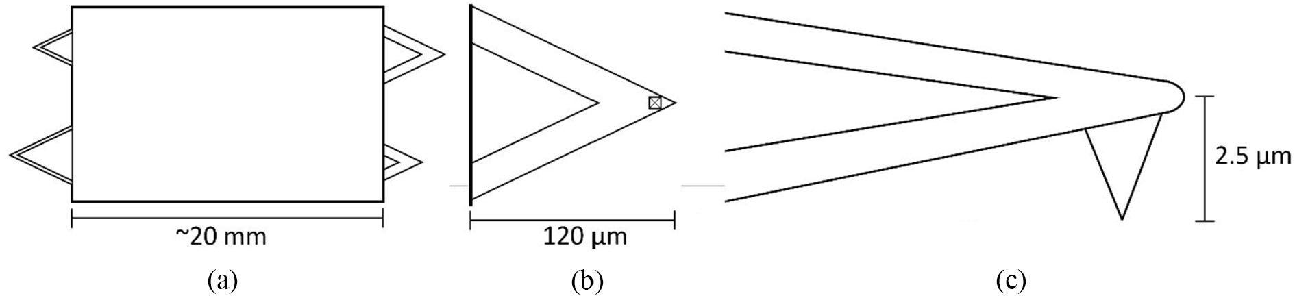
(a) basic schematic of DNP-10 AFM probe, (b) magnified view of underside of cantilever B, and (c) magnified side-on view of the tip of cantilever B.
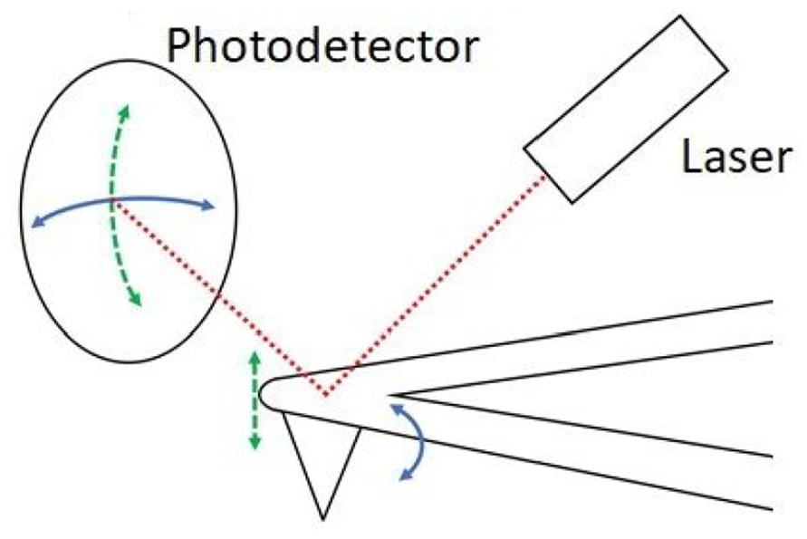
A schematic of the basic operation of AFM. A laser is directed towards the tip of the cantilever, and any vertical translation or lateral twisting of the tip is recorded by the path of the laser on a photodetector.
Nano-hardness
The nano-hardness of the coatings is used to characterise the hardness of the thin coating candidates which can be used as a measure of wear resistance. 52 Each coating was subject to eight indents at different locations on the coated surface, and for each indent four loading and unloading cycles were applied. These loading cycles were at 0.6, 2.1, 3.1 and 4.1 mN. A Berkovich tip was used for all indents, with a Young’s modulus of 1141 GPa and a Poisson’s ratio of 0.07. The nano-hardness for each loading and unloading cycle of each indent is recorded and averaged to provide an accurate measure of the nano-hardness of each coating candidate. The nano-hardness machine with annotated components is presented in Figure 5.
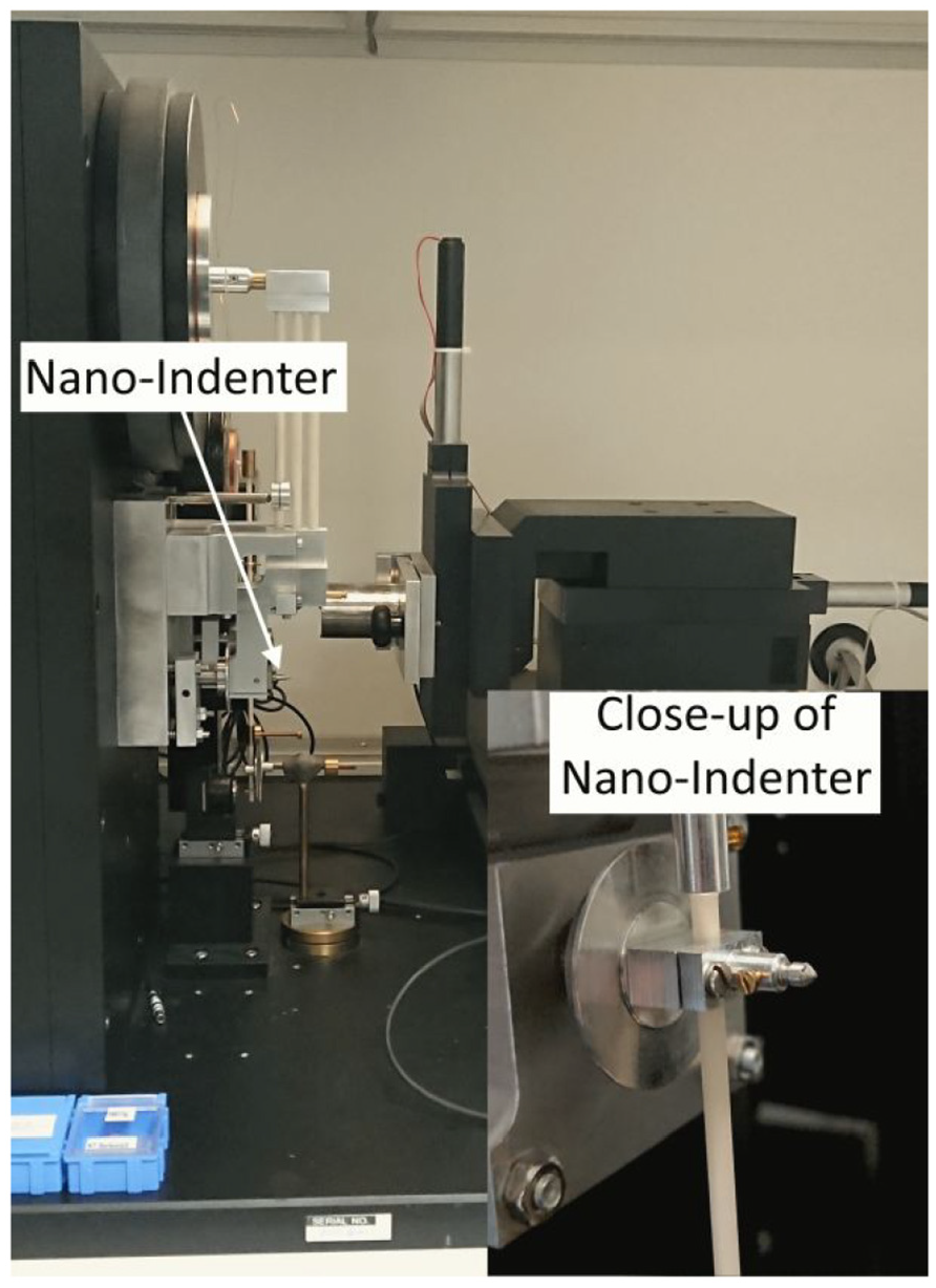
Nano-hardness machine.
Wear characterisation
The wear resistance of the coatings is evaluated as well as the frictional performance to determine the realistic performance of the coatings. In such an application as between the piston skirt and the cylinder liner, a coating may facilitate highly lubricious contact, but this may be of little value if it cannot maintain good coverage of the contacting surfaces over the lifetime of the component. Wear resistance of GO coatings are evaluated and benchmarked against commonly used commercial graphite coatings and uncoated steel surface.
Nano-wear characterisation was conducted using a Veeco Dimension 3100 AFM. The AFM enables the measurement of asperity level wear and frictional characteristics of surfaces. It helps in development of the fundamental understanding of the underlying mechanism of wear of a surface. 53 Therefore, AFM evaluates the wear performance of coatings and compares them to the standard steel surface used for commercial IC engine applications. It is important to quantify the wear resistance of a coating for the service life interpretation. The samples were subjected to nano-wear characterisation by using a single crystal diamond NM-TC probe, with a nominal tip radius of 25 ± 5 nm and nominal cantilever stiffness of 350 N/m. In order to measure lateral forces during the nano-wear test, a blind calibration procedure was adopted using a monolithic silicon nitride crystal with known frictional characteristics as explained in previous research.44,45 The friction is measured using the trace minus retrace method. An initial topography was measured over the scan area of 10 µm × 10 µm to identify a relatively flat area. The surfaces were scratched in LFM model over the scan length of 5 µm in a single line for 40 passes, and friction was recorded at 256 points along the scan length. The probe was then disengaged, and topography was measured to determine the depth introduced by the AFM probe during those passes. The overall procedure was repeated for four times at different areas to ensure repeatability.
Numerical model of piston skirt-liner conjunction
The numerical model in this paper comprises a multi-physics approach, considering the tribology of the contacts as well as the flexible multi-body dynamics of the single cylinder engine assembly. The simulations have been carried out in the AVL EXCITE™ Power Unit environment. The experimentally obtained topography of the surfaces and the shear strength of asperities from AFM are used to build the boundary lubrication model. The fluid film lubrication is analysed by solution of the Reynolds equation, simultaneously with the boundary lubrication model and taking in to account the rheology of the lubricant. The model inputs span multiple length scales, from the nano-scale shear strength of asperities of the coatings, to the macro-scale dimensions of the modelled piston skirt/cylinder liner contact. This numerical model is designed to simulate coating performance in the real-world application, so the outputs of the model are the macro-scale simulated performance of these coatings.
Fluid film lubrication
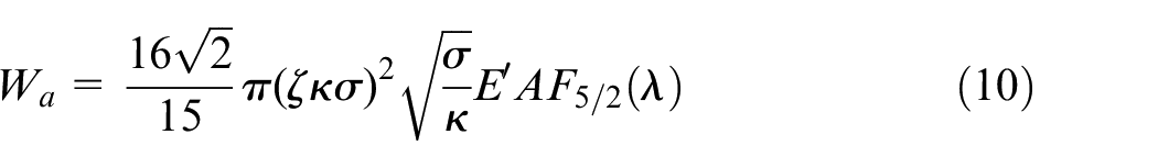
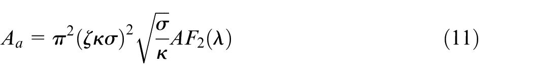
In order to analyse the fluid film lubrication in the conjunction, pressure distribution of the lubricant film across the piston skirt-liner contact should be found. The following form of two-dimensional Reynolds equation is used: 54
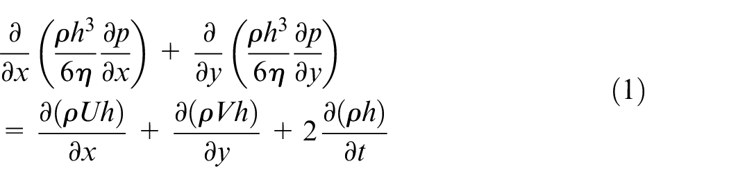
where
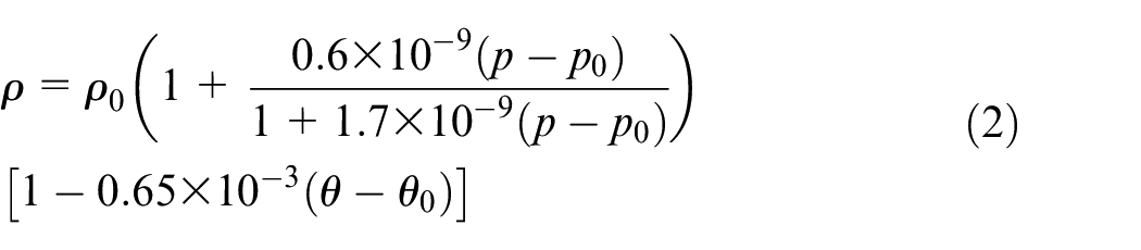
where lubricant density at atmospheric pressure is
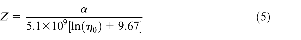
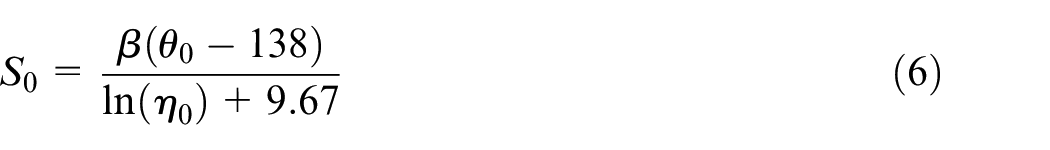
Lubricant viscosity is also pressure and temperature dependent. The Roeland’s equation for lubricant viscosity 57 with the addition of the Houpert for temperature dependency 58 is used as shown below:

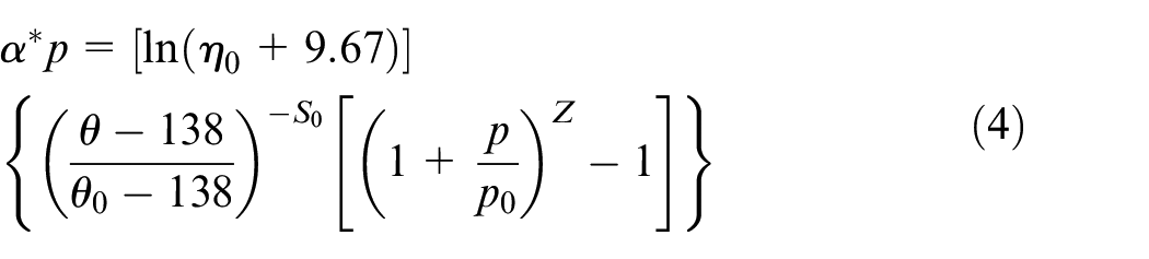
The independent constants for pressure and temperature,
The film thickness distribution is required for the solution of Reynolds equation. For piston skirt–cylinder liner conjunction, the below equation represents the film thickness distribution:
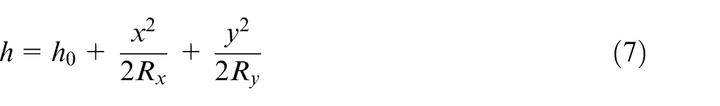
where

and
Asperity contact and friction calculation
The term asperity is used to describe the unevenness of surfaces. No surface is truly smooth and free of asperities. At an atomic level, even those surfaces which have undergone post process finishing, such as polishing to greatly decrease surface roughness, comprise rugged edges and features. Real solids have rough surfaces and make contact only at isolated points where the asperities on the two mating surfaces come together. This is equally true whether the apparent contact area is macroscopic, as in the contact of two nominally flat surfaces, or microscopic, as in the contact of two rough spheres. 41 The Hertzian theory of elasticity was derived by Heinrich Hertz in 1881 and is often used to solve contact problems such as those happening between asperities. 62 This theory is the fundamental concept and is applicable for elementary level modelling of surfaces in contact. 63 The model proposed by Greenwood and Tripp 37 for boundary lubrication considers surface roughness between two rough plane surfaces for simplified asperity geometry and an assumed Gaussian distribution of peak heights. It also assumed the Hertzian theory to be applicable at asperity level.
For the skirt-liner applications, the part of the load which is carried as a result of asperities can be found using calculations provided by Greenwood and Tripp:
A topography measurement is used to find
The boundary friction caused by the asperities is obtained as 40 :

By taking surface topographical measurements, the roughness parameter
Effect of surface roughness on the fluid film lubrication
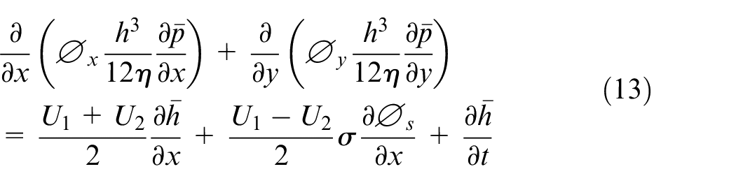
The approach of Patir and Cheng64,65 can be used to replicate the effects of surface roughness on fluid film lubrication and partially lubricated contacts. This is achieved by using an averaged Reynolds equation in terms of pressure and shear flow factors found by numerical simulation, which are functions of the surface roughness characteristics obtained from experiment. The method was created in order to examine the effects of three-dimensional surface roughness for both isotropic and non-isotropic conditions. The general theory is independent of the Gaussian distribution of heights. This method is also used in the current study due to pronounced effect of surface roughness features on some of coatings as is shown in the results section.
The method works by sampling representative areas under specific conditions so that the flow can be analysed independently. Separate flow conditions due to generated pressure in the direction of entrainment (x-direction) and side-leakage (y-direction) as well as that due to shear at the bounding solid surfaces are obtained. These are then quantified and included in the standard Reynolds equation to form the Averaged Reynolds equation as shown below:
Multi-physics system level model
As mentioned earlier, the overall model is of multi-physics nature comprising tribology and dynamics. This facilitated the application of realistic loading to the tribological model considering inertial effects obtained from dynamics. It also enables the implicit coupling between tribology and dynamics by application of the friction force obtained from the tribology in the Lagrangian formulation of equations of motion.
An overview of the simulation model is shown in Figure 6. The model represents a single cylinder engine running at 3000 rpm. The model is made up of five flexible bodies comprising liner, piston, piston-pin, conrod and a bearing-pin as well as the ground. Bodies are constrained by six joints: two representing the skirt-liner boundary and hydrodynamic contact and four revolute joints representing small end and big end bearings. The assumption of the revolute joint for bearings is to simplify the model and only represent the complex mixed lubrication in the skirt conjunctions.
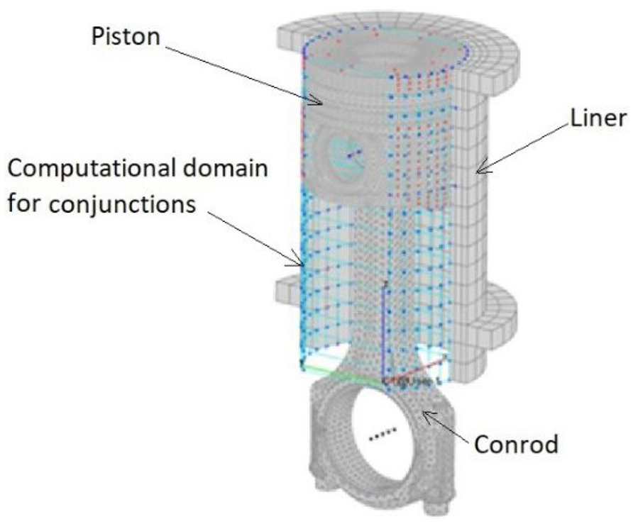
The system level tribo-dynamic model considering component flexibility.
In summary, the experimental data gathered about the GO coatings through various methods is used to inform the numerical model of the piston skirt/cylinder liner conjunction, which then simulates the operation of these coatings in a single cylinder engine and outputs various data such as the boundary friction in the contact and film thickness. A route diagram for this is shown in Figure 7.
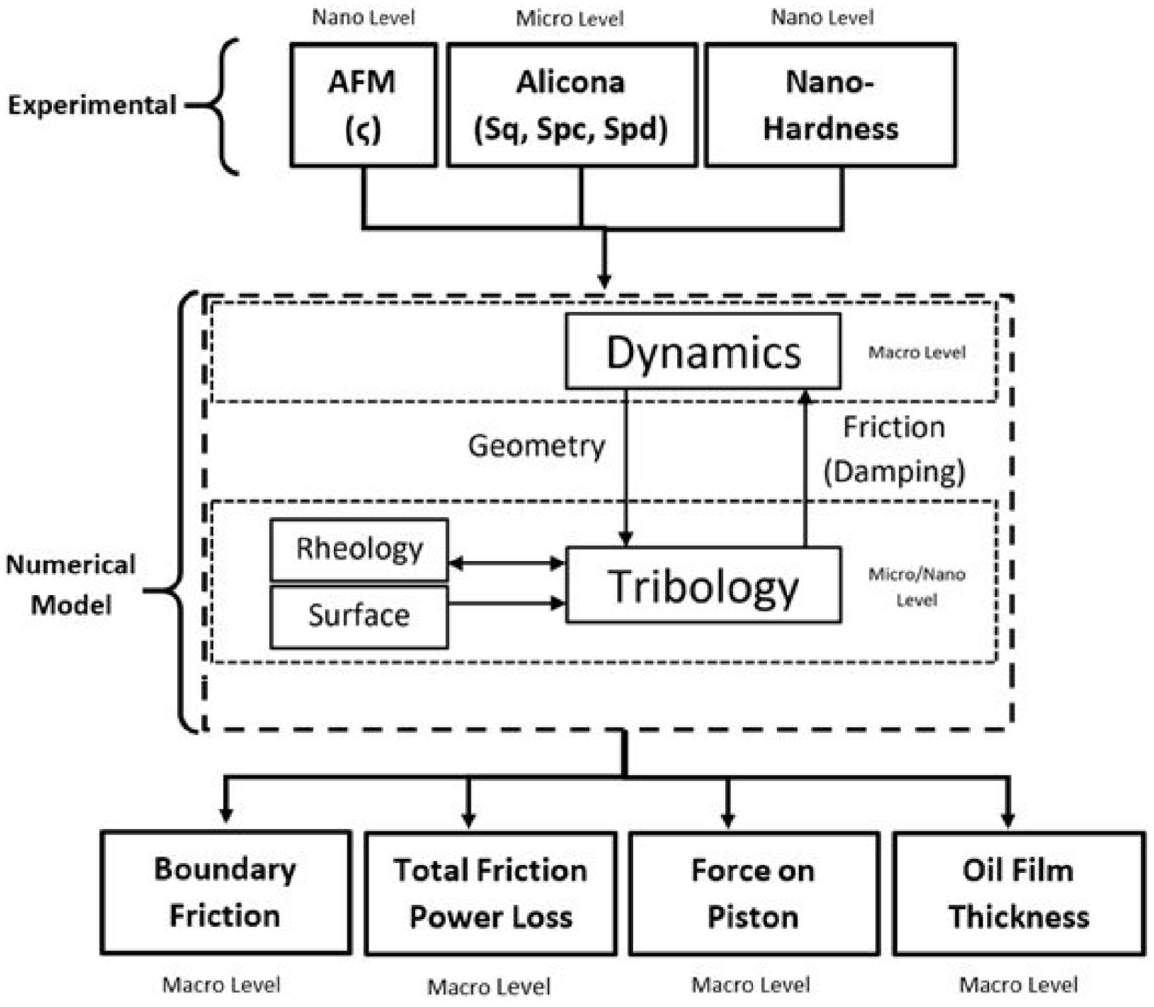
The route diagram outlining the process from experimental inputs to numerical outputs.
Results
Three candidate coatings are deposited on steel substrates by EPD under differing deposition conditions to create surfaces with varying topographies, morphologies and frictional properties which influence the tribological performance of the candidate coatings. All coatings are deposited at a deposition voltage of 6.5 V and with a 40 mm distance between the coating electrode and the substrate(s). The concentration of the GO solution was maintained at 0.1 g/L for all depositions. The length of the deposition is altered for each candidate coating: Coating 1 has a coating time of 1800 s, Coating 2 has a coating time of 3600 s and Coating 3 has a coating time of 5400 s. Only one deposition parameter is altered in this work which, in turn, influences the topographical phenomenon, material properties, etc., which are primarily responsible for affecting the tribological performance of the coating in question. In other words, altering the deposition time is a simple way of generating surfaces with different tribological performances suitable for demonstrating the multi-scale approach applied here.
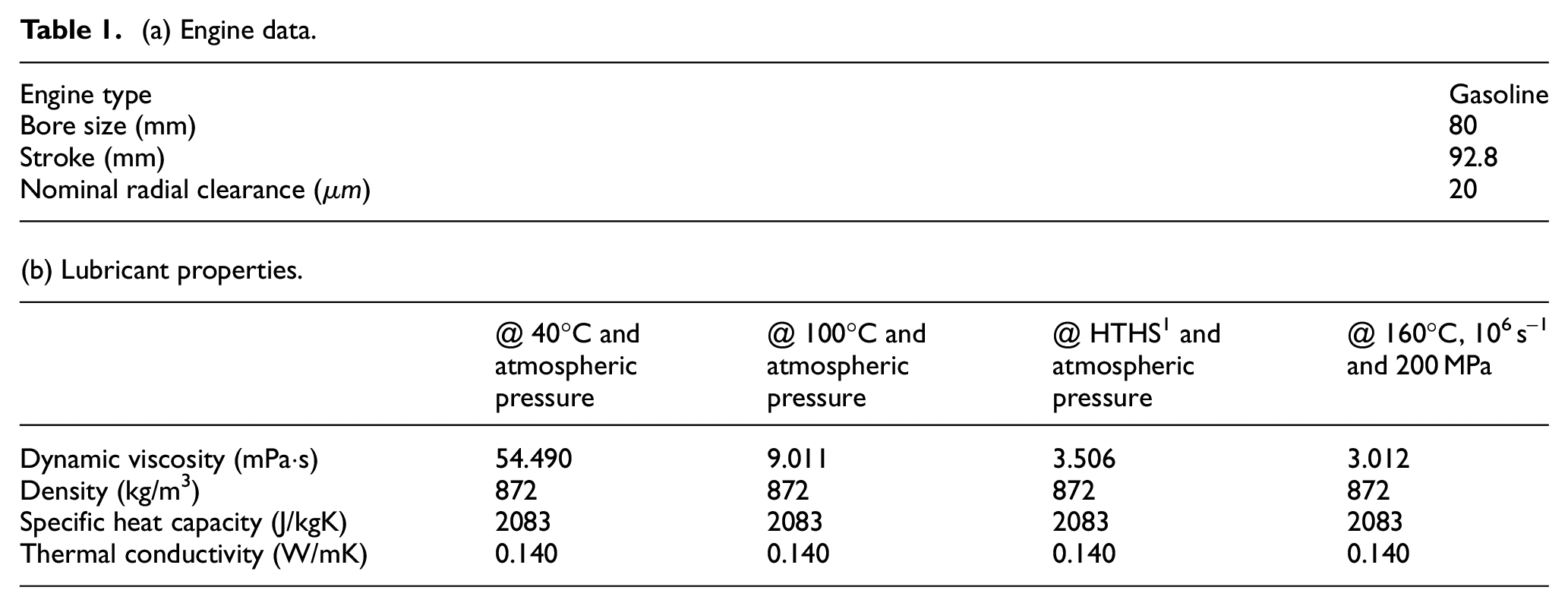
These three candidate coatings are first experimentally characterised in terms of topography, morphology, asperity level frictional properties and their wear resistance. Then, they are considered in the application of the piston skirt/cylinder liner conjunction within a single cylinder ICE, where they are simulated in the computational environment. This conjunction has a large impact on the overall friction of the ICE, especially at top dead centre (TDC) and bottom dead centre (BDC), where the direction of motion of the piston is reversed. At TDC and BDC the boundary lubrication regime dominates and high friction is observed, so this is where we will see the biggest reduction in friction from the deposition(s). The film thickness is assumed to be small compared to the oil film thickness generated during simulation. The engine data and lubricant properties considered in the simulations are provided in Table 1(a) and (b).
(a) Engine data.
As the benchmark for the performance of proposed coatings, a commercial graphite coating for piston-skirt application is tested using the similar approach mentioned above. In addition, an uncoated steel is used as the second benchmark to provide comparison against steel pistons which are becoming more common in modern engine designs.
In the simulation model, the boundary friction is assessed based on the Greenwood and Tripp asperity contact model, for which the topographical nature of the coating surfaces is required as well as the nanoscale boundary shear strength of asperities. This is achieved through non-contact metrological measurements using a 3D optical variance technique and an AFM, respectively. The topographical data are also required for the average flow model for the viscous friction purposes.
Topography
The peak height distribution of each surface is presented in Figure 8 as measured using Alicona InfiniteFocus G4 (following a method similar to that seen in 66 ). Multiple topography scans are performed across a range of areas on each sample surface to ensure the repeatability of the surface characteristics. A Gaussian distribution is assumed for the Greenwood and Tripp asperity contact model; but the simulations can take into account non-Gaussian distributions. To determine if the distributions can be considered Gaussian, the data in Figure 8 is compared to a Gaussian distribution with the same statistical quantities as the measured data. As is revealed in Figure 8, due to deviations from the Gaussian distribution for some surfaces, scans of real surfaces are used to inform the simulations and provides a better accuracy than simply inputting metrological parameters and assuming the Gaussian peak height distribution.
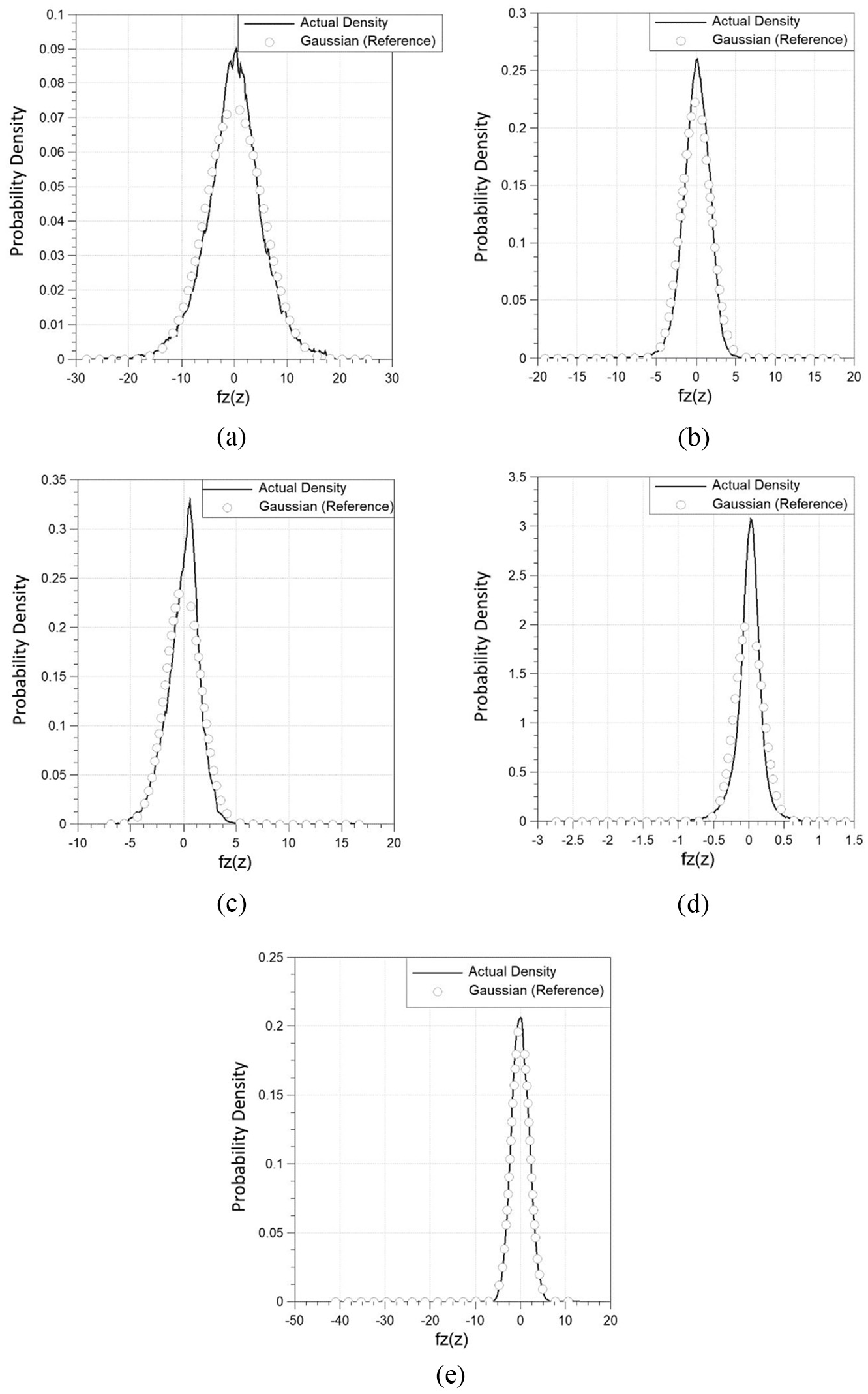
Peak height distributions for each coating compared against the Gaussian distribution: (a) coating 1, (b) coating 2, (c) coating 3, (d) graphite commercial coating, and (e) uncoated AISI 8620 steel.
Figure 9 shows sample scans for one site on each of the surfaces. As mentioned earlier, topography measurements are used to find the roughness parameter,
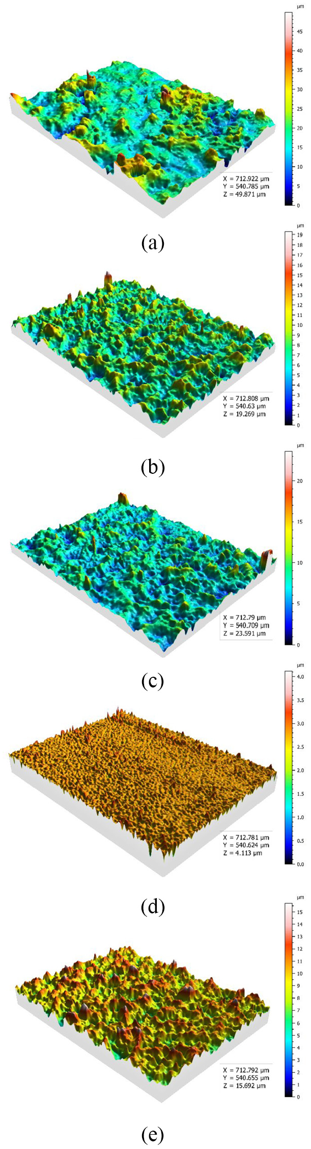
Topographies from one site of: (a) coating 1, (b) coating 2, (c) coating 3, (d) graphite commercial coating, and (e) uncoated AISI 8620 steel.
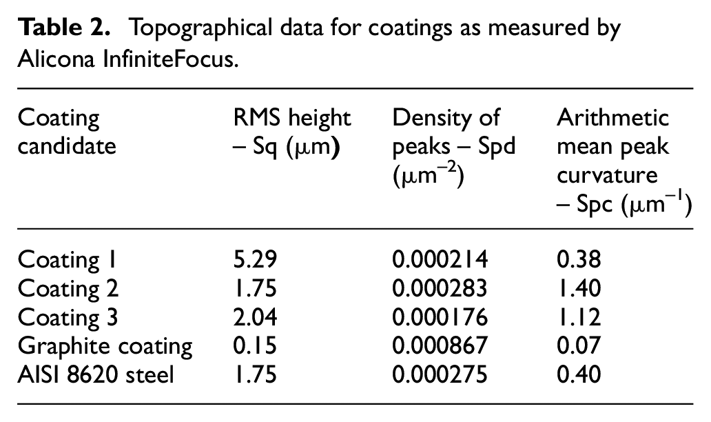
Topographical data for coatings as measured by Alicona InfiniteFocus.
Morphology
SEM images of the Coating 1, Coating 2 and Coating 3 are presented in Figure 10. These images provide further insight into the morphology of coatings and potential effects observed in results. From the image of the GO before deposition in Figure 1, it is clear that the GO exhibits a flake-like structure. Looking at the images of deposited GO coatings in Figure 10, this flake-like structure is still observed to some degree, although Coating 1 displays a much coarser surface than Coating 2 or Coating 3. As the coating time increases, the coverage of the surfaces seems to provide smoother surfaces as also observed and quantified from topography measurement in Table 2. This is expected as a longer coating time through EPD would reveal this effect.32,33 As a consequence, by longer coating time, smoother surfaces with smaller roughness values and shorter wavelength of asperities is achieved which is expected to affect the boundary and viscous effects.
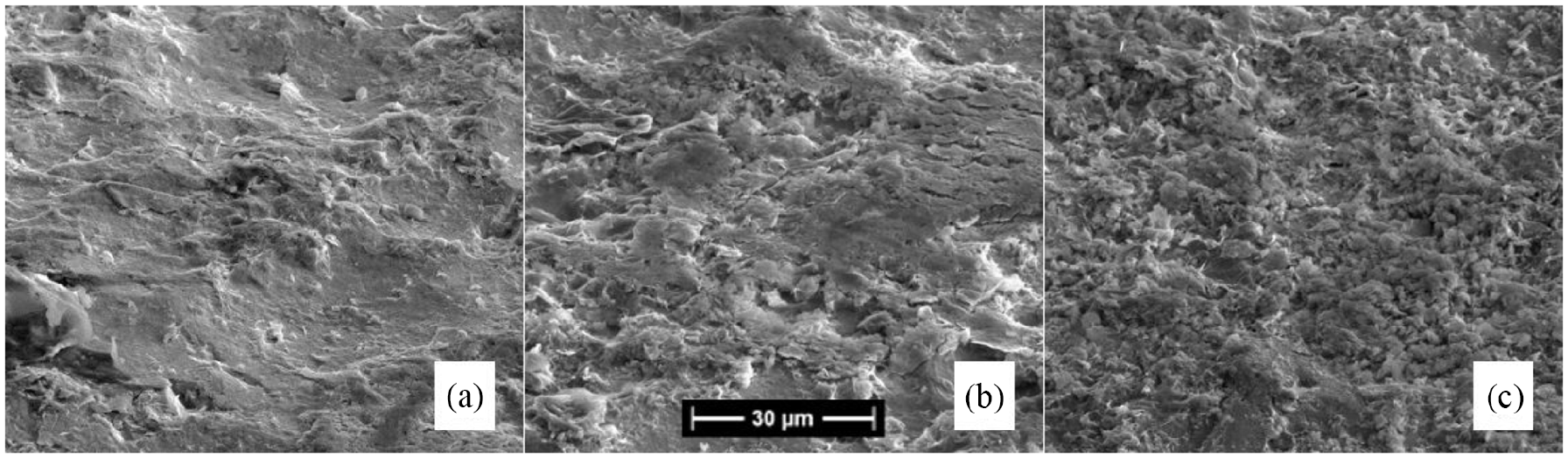
SEM electron micrograph of morphology of: (a) coating 1, (b) coating 2, and (c) coating 3.
Nano-friction
The friction at the asperity-level is characterised using AFM in LFM mode, which can then be input into the Greenwood and Tripp model for boundary lubrication to yield information about the frictional performance of the coatings in real-world applications, as detailed earlier. A sample of the data obtained from AFM for Coating 1, Coating 2, Coating 3, Graphite and Uncoated AISI 8620 steel are presented in Figure 11. The figure shows measurements taken from three sites across Coating 1 and across a range of loads, from 15 to 55 nN. This load range represents asperity contact pressure of 2.16 to 5.38 GPa, which is inline with the asperity contact pressure of up to 4.8 GPa during a full engine cycle investigated in the results section. The slope of the line of best fit for each measured site is equal to the average shear strength of asperities for the 5 µm × 5 µm sample area measured at each site.
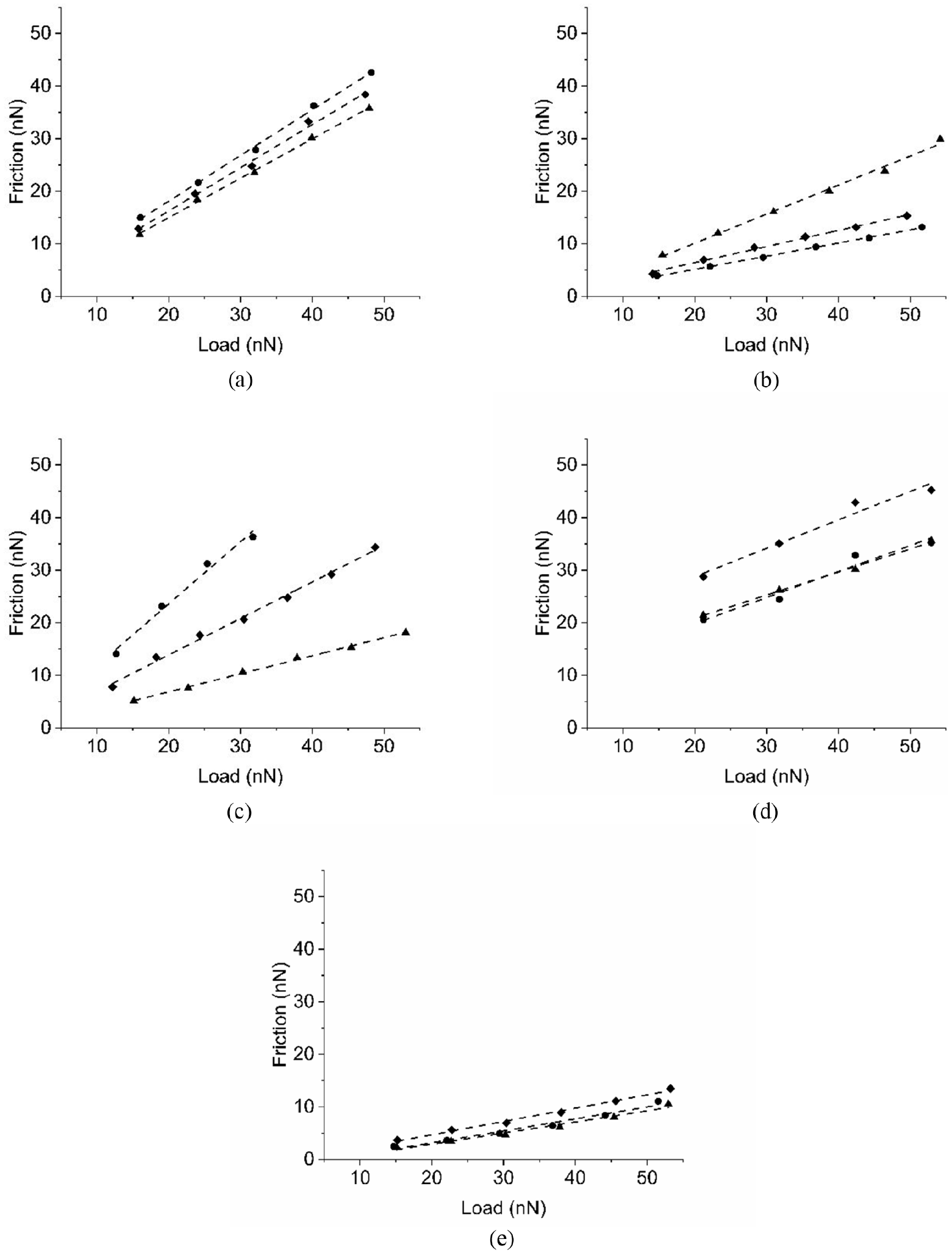
AFM data for three sites on: (a) coating 1, (b) coating 2, (c) coating 3, (d) graphite, and (e) uncoated AISI 8620 Steel. The legend for all (a)–(e) is shown in (f).
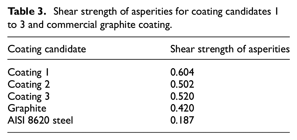
The shear strength of asperities,
Shear strength of asperities for coating candidates 1 to 3 and commercial graphite coating.
Nano-hardness
The nano-hardness of the three candidate coatings as well as uncoated steel are measured to provide insight into their wear properties. The purpose of this measurement is to compare coating data with the uncoated steel as the benchmark material. The hysteresis curves for the four loading cycles on one site for Coating 1 is presented in Figure 12. All measurements were conducted with the maximum load of 4 mN, leading to a sub-micron deformation. The same measurement is repeated on five sites across each sample to investigate the repeatability of the data, following the established continuous stiffness measurement methodology. 68 Figure 13 shows the hardness versus penetration for all indents on all samples. The standard deviation is also provided on each graph.
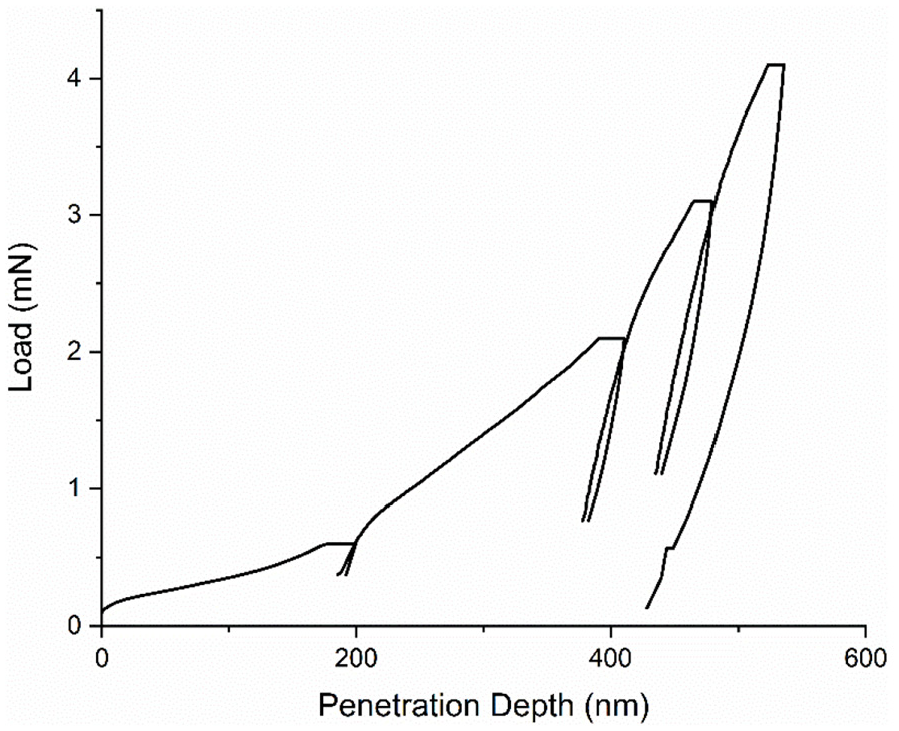
Example hysteresis curves for one indent on coating 1.
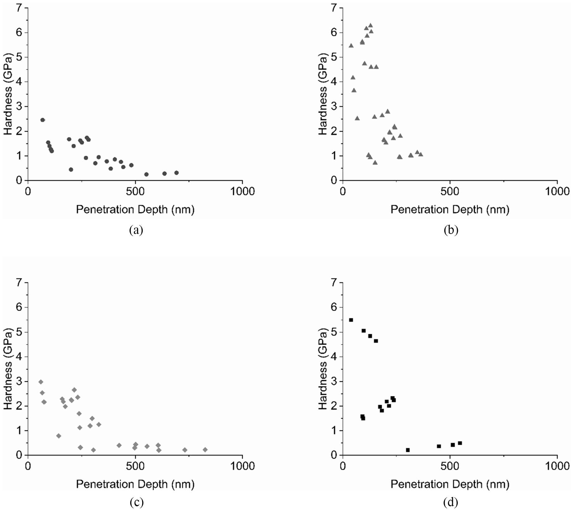
Hardness measurements for: (a) coating 1, (b) coating 2, (c) coating 3, and (d) uncoated AISI 8620 steel.
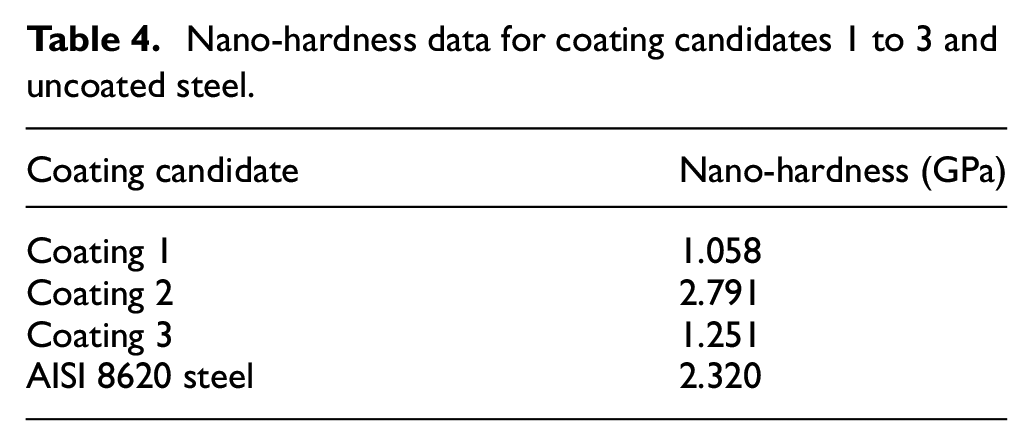
The averaged nano-hardness values for all three candidate coatings are presented in Table 4. From this data it is revealed that Coating 3 exhibits the highest nano-hardness at almost 3 GPa, and Coating 1 has the lowest nano-hardness at around 1 GPa. In compare with the nano-hardness value of steel, it is observed that the hardness of proposed coatings are comparable and in the same order of the one for steel. This is an indication of practical level of wear resistance of the coatings to be used in an engine conjunction. Further wear characterisation is performed in the next section.
Nano-hardness data for coating candidates 1 to 3 and uncoated steel.
Wear resistance
The wear performance of the candidate coatings, the commercial graphite coating and the uncoated steel are characterised using scratch test performed using AFM. NM-TC tip with cantilever stiffness of
The 3D topography of the wear marks on each sample are presented in Figure 14. The maximum wear depth of each sample is presented in Table 5. Results show that the GO coatings provide superior wear resistance in comparison with the commercial graphite coating. The wear performance of GO coatings are also comparable with the one demonstrated by steel. GO coatings can be utilised for piston skirt–cylinder liner conjunction instead of the commercially available graphite coatings and improve the wear performance significantly and even to the level of steel.
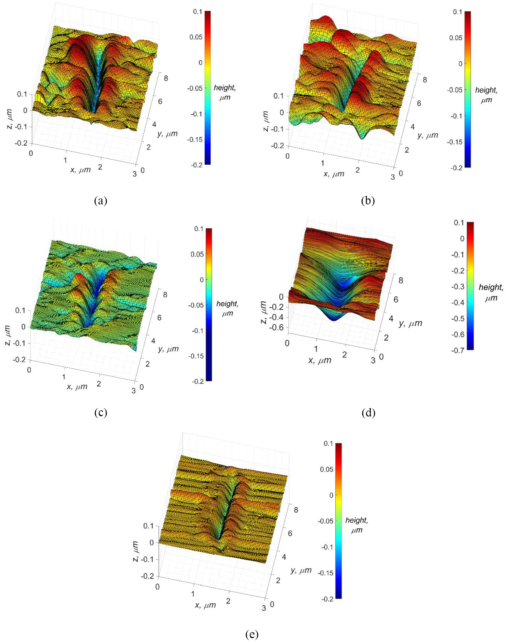
3D topography of the wear marks after 40 passes for: (a) coating 1, (b) coating 2, (c) coating 3, (d) graphite, and (e) uncoated AISI 8620steel.
Maximum wear depth of samples.
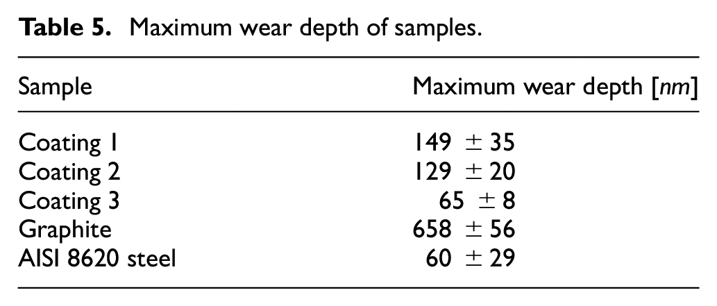
It should be noted that the presented wear characterisation here is comparative, comparing the performance of GO coating against commercially used graphite coating and uncoated steel. This methodology can be further developed to obtain linear and non-linear wear rates to be used in any transient (cyclic) wear analysis which is not in the scope of current work. Research by Noel et al. 69 explored the wear of copper-based composites at the nano-scale using AFM and found that for higher loads in the region of tens of nano-newtons, ‘Archard-like’ wear was observed. Similarly, Kuznetsova et al. 70 used AFM to examine the friction and wear of Cr–O–N coatings at the nano-scale under similar loads to Noel et al. and made similar observations. Considering similarities between these works and the work presented in the current paper, it is believed that the Archard law would be one of applicable methods to conduct a multi-scale transient wear prediction as further study. Also, in terms of integrity of GO coating for practical application which includes its adhesion to the substrate, it is important to thoroughly characterise that. This is subject of further investigation which is outside the scope of current paper.
Simulation results
Following the surface characterisation and benchmarking GO coatings against graphite and steel in terms of asperity level characteristics, the tribological performance of these coatings are investigated at conjunction level in a piston skirt–cylinder liner contact. This investigation is computational and considers both viscous and boundary frictions as well as system level flexible dynamics response. The three candidate coatings are simulated alongside the commercial graphite coating and uncoated steel until the simulation reached steady state condition. The coatings are applied on the piston skirt against a cross-hatched steel. Results are then recorded for last 1440°, but only one complete cycle of 720° is plotted in following results. In all simulations of this section, the engine speed is considered to be 3000 rpm. The cylinder pressure curve is provided in Figure 15.
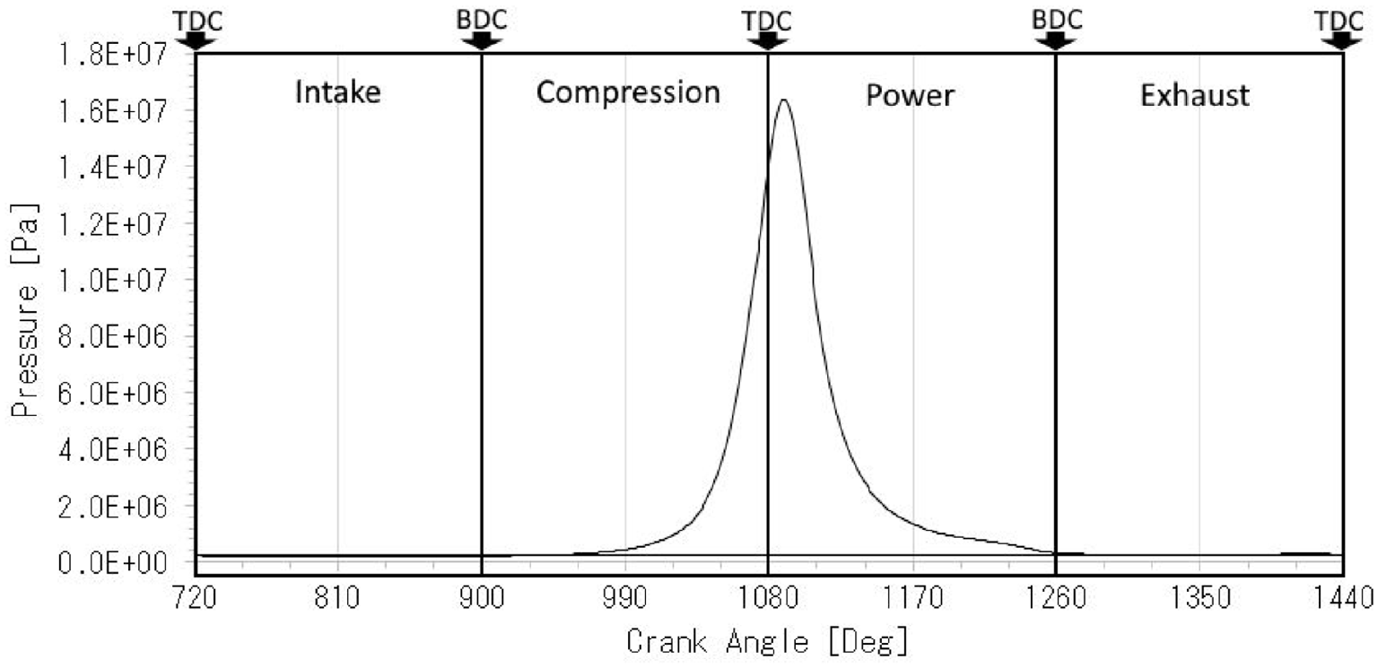
Cylinder pressure curve.
In order to ascertain the effect of surface roughness on the viscous friction, simulations are repeated for coated surfaces using the classic Reynolds equation (equation (1)) which assumed smooth surfaces and the average flow version of Reynolds equation according to Patir and Cheng64,65 (equation (13)) considering surface topography and low orientation. Figure 16 displays the simulated minimum oil film thickness between the piston skirt and the cylinder liner across one full engine cycle (intake, compression, power and exhaust) for all modelled coatings. In Figure 16(a), results of simulation using equation 1 are provided, showing negligible difference between different coatings and surfaces. This is due to lack of roughness effect in the fluid film lubrication model and negligible effect on the boundary friction. Figure 16(b) shows the results of average flow model of equation 13. Results reveal the pronounced effect of topography on the film thickness and the tribological response of the system, confirming the necessity of using this method. The film thickness results also show the superior performance of Coating 1 as expected on the fluid film lubrication and the film thickness. This is due to the measured topography of this coating, acting as a nano-texture and enhancing the load carrying capacity. The enhanced film not only results in improved friction, but also lowers the transient wear at conjunction level. The latter is due to the effect of surface separation (film thickness in this case) in addition to the coating wear resistance shown in the previous section on the conjunction level wear.

Figure 17 displays the simulated total friction on the piston skirt across one full engine cycle for all modelled coatings. As explained above, Coating 1 enhances the frictional performance of the conjunction by up to 15% at the mid-stroke. These friction reductions happen at the mid-stroke, revealing the dominant effect of velocity dependent Couette flow term of Reynolds equation in the observed enhancement.
The boundary friction is shown in Figure 18. The results of this figure show that the uncoated steel has significantly lower boundary friction which is due to its lower shear strength of asperities and lower surface roughness. It should be noted that this gain is significantly smaller in magnitude than the overall friction reduction observed in Figure 17. In addition, as mentioned in the characterisation section, the lower shear strength of asperities observed for uncoated steel is theoretical since in real engine application the uncoated surfaces are soon deposited by carbon-based by-products, causing much higher coefficients. Hence, the slim advantage of the uncoated surface in terms of the boundary friction is likely to be eliminated in the real application. In addition, since the boundary friction force has its peak near reversal points, its effect is likely to be further suppressed when considering the power loss rather than the force.
Figure 19 displays the simulated total frictional power loss at the piston skirt/cylinder liner interface across one full engine cycle for all modelled surfaces. Similar to the trend observed for total friction force, Coating 1 provides significant improvement (up to 14%) in the total power loss. It should be noted that the minute theoretical improvement of the boundary friction by uncoated steel is eliminated when considering power loss instead of friction force since the boundary friction prevails near reversal points which has virtually zero velocity.
Conclusion
The tribological performance of GO coatings on the piston skirt of a gasoline engine is evaluated. The frictional performance and the wear resistance of three variants of the proposed coating are benchmarked against uncoated steel and commercially available Graphite skirts. All surfaces are experimentally characterised for asperity level friction, topography and wear resistance using optical microscopy, SEM, nanoindentation and AFM. The conjunction and system level performance of these coatings considering boundary and viscous lubrications and system dynamics are evaluated using a tribo-dynamic model.
Results revealed that by incorporating appropriate GO coating, the total frictional power loss of the piston skirt to cylinder liner conjunction can be improved by up to 14%, suggesting that GO is promising in this regard. This is despite minor increase in the boundary friction which is negligible particularly because the boundary friction has its highest values near reversal points, minimising its effect on the net power loss. The major gain is achieved in the viscous friction and during the mid-stroke due to the asperity level texture-like pattern obtained by the coating. This maximises the effect on the total power loss because of the highest velocity at mid-stroke.
It is also observed that the wear resistance of the coatings is comparable with uncoated steel surface and significantly higher than commercially available graphite. It can be concluded that the proposed coatings provide a practically and commercially viable option for the tribological enhancement of the piston skirt conjunctions in comparison with the commercially available graphite coated aluminium or uncoated steel surfaces.
Results presented are for idealised experimental conditions and further work focussing on applying the methodology presented to a specific solid lubricant case-study would be a logical and valuable next step. In addition to this, associating more properties of the GO films with the numerical simulation, such as a more in depth wear analysis and examination of how the GO films deform in operation, would work towards a more complete understanding of how these coatings would perform in the real world.
Footnotes
Appendix
Declaration of conflicting interests
The author(s) declared no potential conflicts of interest with respect to the research, authorship, and/or publication of this article.
Funding
The author(s) received no financial support for the research, authorship, and/or publication of this article.