
Abstract
Liquefied natural gas is emerging as viable and potentially sustainable transportation fuel with intrinsic economic and environmental benefits. Liquefied natural gas possesses thermomechanical exergy amounting to ∼1 MJ kg-1 which is currently wasted on liquefied natural gas vehicles, while it could be used to produce useful work. The present investigation proposes an indirect means of obtaining useful work from liquefied natural gas through charge cooling and also demonstrates additional benefits in terms of NOx emissions and power density. A thermodynamic engine model was used to quantify the performance benefits of such a strategy for a homogeneous-charge, spark-ignited, stoichiometric natural gas engine. Four fuelling strategies were compared in terms of fuel consumption, mean effective pressure and NOx emissions. Compared to the conventional port-injected natural gas engine (where gaseous fuel is injected), it was found that directly injecting the liquid phase fuel into the cylinder near the start of the compression stroke resulted in approximately -8.9% brake specific fuel consumption, +18.5% brake mean effective pressure and -51% brake specific NOx depending on the operating point. Port-injection of the fuel in the liquid phase carried similar benefits, while direct injection of the fuel in the gaseous phase resulted in minor efficiency penalties (∼+1.3% brake specific fuel consumption). This work highlights the future potential of liquefied natural gas vehicles to achieve high specific power, high efficiency and ultra-low emissions (such as NOx) by tailoring the fuel system to fully exploit the cryogenic properties of the fuel.
Introduction
Reducing emissions and decarbonising the transport sector is of critical importance. However, this is particularly challenging for heavy commercial vehicles where a high energy density energy carrier is essential to deliver a long-range and reduce vehicle down-time in order to be economically viable. Natural gas (NG) is abundant, widely available and economically competitive, with significant intrinsic environmental benefits compared to diesel, the current dominant alternative. In liquid form, liquefied natural gas (LNG) has favourable properties to be used in heavy, long-range vehicles. LNG has been increasingly adopted in heavy-duty road vehicles and shipping vessels and is of interest as a potential aviation fuel. The spread of LNG as a vehicle fuel is being enabled by increased fuelling infrastructure in recent years. In the EU, for example, LNG filling stations are up from 29 in 2013 to 104 in 2017 1 and 155 in 2018. 2 The cost of LNG per unit energy is approximately 45% less than diesel, depending on time and region.3,4 Under ideal considerations, combustion of methane (the main constituent of NG) leads to approximately a 27.5% reduction in greenhouse gas (GHG) emissions compared to diesel fuel. 5 However, considering the full well-to-wheel (WtW) life-cycle impact the GHG reduction in LNG vehicles with current technology is still significant, in the region of 10%–15%, 6 6.5%–15.1%, 7 or 16%. 8 Biogas derived locally from waste such as landfill gas or agricultural waste, for example, provides a sustainable pathway for further net GHG reduction. It is forecast in Europe at least 30% of NG in transport will be renewable by 2030. 2
In terms of regulated emissions, the amount of emission reduction is highly dependent on the NG engine operating strategy. The main strategies are spark ignited (SI) stoichiometric pure NG, SI lean-burn pure NG, and dual-fuel NG and diesel. Stoichiometric SI engines are able to achieve the lowest overall emissions of NOx and unburned hydrocarbons (HC) because of the benefit of a three-way catalyst (TWC) and has been the preferred strategy to achieve Euro VI regulations. 9 A significant and perhaps prohibitive limitation of lean-burn strategies are excessive HC emissions, which are primarily methane10,11 that cannot be easily treated with an oxidation catalyst due to low exhaust temperatures.12,13 Catalysts are also unable to treat NOx due to high exhaust oxygen concentration. Dual-fuel engines are inherently a compromise between diesel and NG operation and emissions depend largely on the NG substitution fraction. Particulate matter (PM) and NOx from the diesel combustion remain a problem for a high diesel ratio, 14 whereas methane emissions can be become a problem for high NG fractions,14,15 particularly at low load.16,17 Despite benefits in terms of emissions, the drawback of a stoichiometric SI strategy is lower fuel efficiency and therefore higher GHGs due to pumping losses, knock limits and higher heat losses. This article proposes a solution to this.
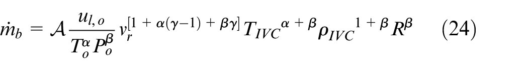
A problem with current LNG fuelled vehicles is that the thermomechanical exergy of the fuel is wasted. LNG is a cryogenic liquid stored at approximately 110–150 K depending on the storage pressure, meaning it possesses exergy and useful work could be done while bringing it into equilibrium with the surrounding environment before being consumed in the engine. Current practise is to pass the LNG through a heat exchanger where the fuel is vaporised, usually by exchanging heat with the engine coolant, and then delivered to the engine in the gaseous phase. Therefore, there is currently no fundamental difference between an engine on a compressed natural gas (CNG) or an LNG vehicle; they both deliver the fuel into the engine in the gaseous phase and no useful work is done during the vaporisation process of LNG. The amount of thermomechanical exergy

where subscript
An attractive alternative cold-utilisation method is to use the LNG to cool the engine intake air to potentially sub-ambient temperatures. Charge cooling is known to improve the performance of IC engines through increased mean effective pressure (MEP), increasing efficiency through reduced heat losses and extending knock limits, and decreasing NOx emissions. For example, Stovell et al. 22 conducted experiments on a NG engine and showed that reducing the intake temperature from 54°C to 10°C increased the knock limited brake mean effective pressure (BMEP) by 31% for a fixed ignition timing. Experiments by Klimstra and Westing 23 demonstrated approximately a 25% reduction in specific NOx emissions by reducing the intake temperature from 40°C to 30°C on a NG engine.
This article quantifies, for the first time, the potential performance benefit in terms of fuel efficiency and NOx emissions of LNG-enabled charge cooling through detailed thermodynamic modelling. This is achieved by directly comparing an LNG charge cooled engine with the conventional port-injected (PFI) CNG engine while ensuring a high level of commonality to isolate the charge cooling effects. We ask the question –given the same ‘rules’ (same engine architecture, knock criteria, boundary conditions, etc.), how do various fuelling strategies compare in terms of BMEP, fuel consumption and NOx emissions in the context of a stoichiometric SI engine? The fuelling strategies considered are port fuel injection (PFI) and direct injection (DI) for both gas (CNG) and liquid-phase (LNG) injection and are defined in the next section. First, the amount of charge cooling, or charge heating in the case of DI-CNG, is quantified and factors which effect this prediction are assessed. Then the performance implications are briefly quantified using an ideal cycle. This is followed by a description of the detailed engine model used for deeper analysis and the results are presented. We show that the additional specific work gained from LNG evaporative charge cooling can be greater than the theoretical maximum work that could be gained from a dedicated LNG thermomechanical exergy harvesting system. The mechanism for gaining additional specific work from LNG evaporative charge cooling is a combination of reduced heat losses, increased compression ratio and advanced spark timing. The fuel efficiency improvement predictions are comparable to moving from a stoichiometric to lean-burn strategy, which have been demonstrated to be in the range of 3%-8%. 24 Importantly, the LNG charge cooled stoichiometric method retains the ability to use a three-way-catalyst (TWC) and give ultra-low exhaust emissions.
Fuelling strategies
To achieve the goal of a homogeneous air and fuel mixture in the engine cylinder at the point of ignition there are a variety of options available. First, the fuel can be either introduced to the air in the air intake system or injected directly into the cylinder. Second, with LNG stored on the vehicle, the fuel may either be injected in the gaseous phase (CNG) or in the liquid phase (LNG). These strategies are summarised in Figure 1.
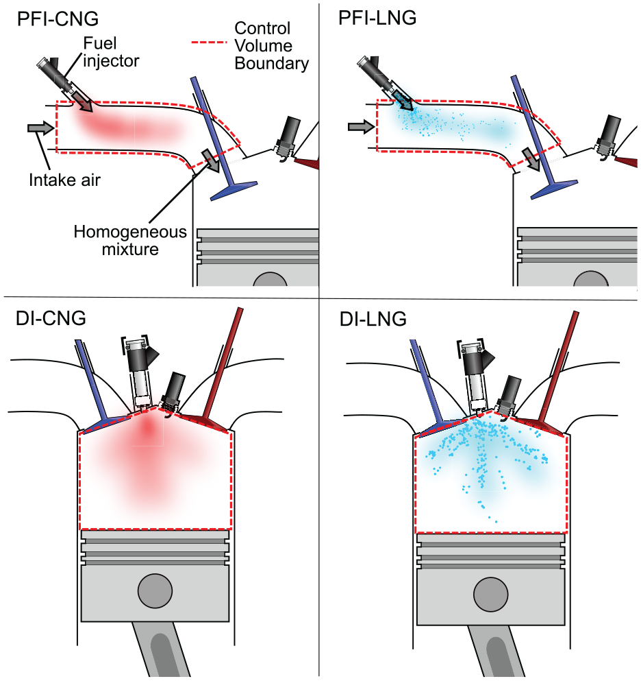
Mixture preparation strategies available for an LNG vehicle.
This section presents a first-law analysis to quantify the charge cooling potential of each strategy. Sensitivity of the temperature change to fuel composition, fuel injection conditions and air fuel ratio (AFR) are also considered. The PFI strategy is modelled as a constant pressure mixing process such that the mixture reaches a uniform temperature before being inducted into the cylinder. DI strategies are modelled as constant volume mixing with the fuel being injected into the cylinder at bottom dead centre (BDC) with the intake valve closed and instantaneous thermodynamic equilibrium results.
In terms of how these idealisations relate to real engines; the PFI strategy as described here encompasses any method where the fuel is introduced sufficiently far upstream of the intake valve such that the mixture homogenises before induction provided there is negligible heat transfer with the intake system walls. The instantaneous DI strategy considered here is an idealisation whose validity depends on the relative time scales of injection, evaporation and mixing compared to the engine speed. The detailed engine model presented later investigates the effect of non-instantaneous injection and evaporation.
An energy balance for adiabatic, constant pressure mixing gives

where
If ideal gas behaviour and constant specific heats are assumed, a first approximation for the resulting mixture temperature (
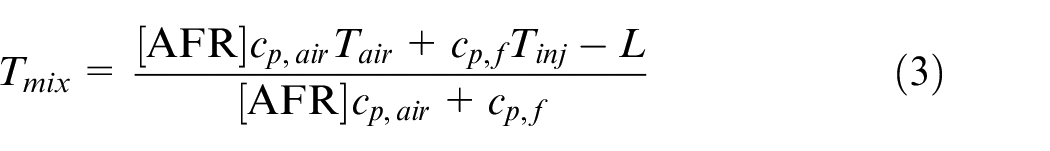
where
Mixture conditions for the key preparation strategies for stoichiometric mixture (
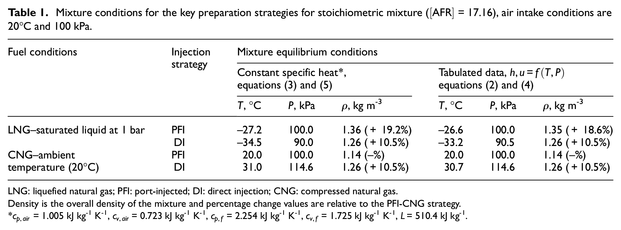
LNG: liquefied natural gas; PFI: port-injected; DI: direct injection; CNG: compressed natural gas.
Density is the overall density of the mixture and percentage change values are relative to the PFI-CNG strategy.
Similarly, an energy balance for injecting fuel into a fixed volume of air (DI) gives

where
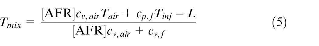
where
The resulting mixture conditions for the various mixture preparation strategies are shown in Table 1. For this analysis, the NG was considered pure methane. Sensitivity to NG composition is considered later and justifies this simplification. This analysis reveals that maximum charge cooling is obtained by directly injecting LNG into the cylinder with the intake valve closed, which is likely indicative of maximum fuel efficiency. This temperature drop was found to be on the order of 55 K. Another key observation is that the evaporative cooling during DI-LNG creates a partial vacuum that will reduce compression work. It is for this reason that the maximum charge density is obtained by injecting LNG into the intake, which is likely indicative of maximum BMEP. This fundamental analysis also reveals that DI-CNG will heat the resulting mixture because the fuel is essentially forced into the cylinder which compresses the air trapped inside. It is worth noting that of course the CNG could be directly injected before intake valve closure (IVC); however, this will prevent some air from being inducted and/or force out air that has already been inducted and from a thermodynamic quasi-steady perspective is equivalent to PFI-CNG.
Equation (2) and equation (4) show the resulting mixture condition is highly dependent on the fuel conditions prior to injection (
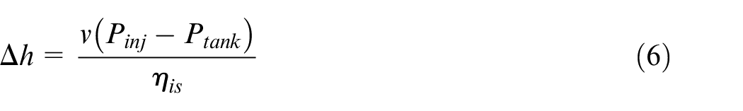
Change in temperature from air/fuel mixing (
Change in temperature from air/fuel mixing (
where
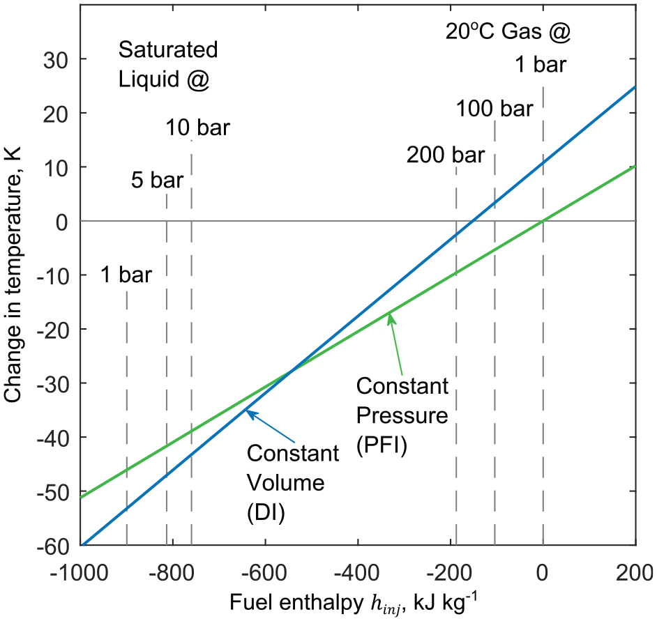
Figure 3 shows that pumping causes only a minor increase in enthalpy and demonstrates the thermodynamic motivation to store LNG at low pressures and pump to the required injection pressure. This will, however, incur cost and added complexity. There is an alignment of motivations here in that maximum fuel density and hence driving range is also obtained for the lowest storage pressures.
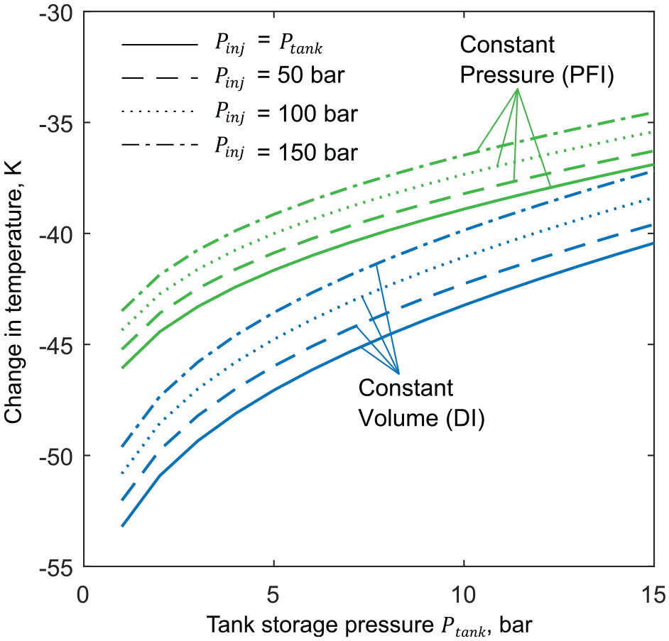
Figure 4 shows the temperature change predictions sensitivity to AFR. For increased
Change in temperature from air/fuel mixing
LNG is primarily methane but includes various heavier hydrocarbons such as ethane and propane. The presence of these components effects the temperature predictions in two ways: by changing the stoichiometric AFR and changing the fuel enthalpy. Table 2 summarises the effect of other components in terms of the charge cooling potential. The cooling potential of pure ethane is greater than that of methane when stored under the same conditions as liquid methane, while that of propane is less. When two typical LNG mixture compositions are considered, the temperature predictions are close (+/-0.1°C) to that of pure methane. This justifies simplifying the fuel to pure methane which is done for the remainder of this study. The effect of butane and heavier hydrocarbons have been omitted since these typically exist in concentrations of < 1%.
LNG charge cooling effect dependence on fuel composition for constant pressure mixing.
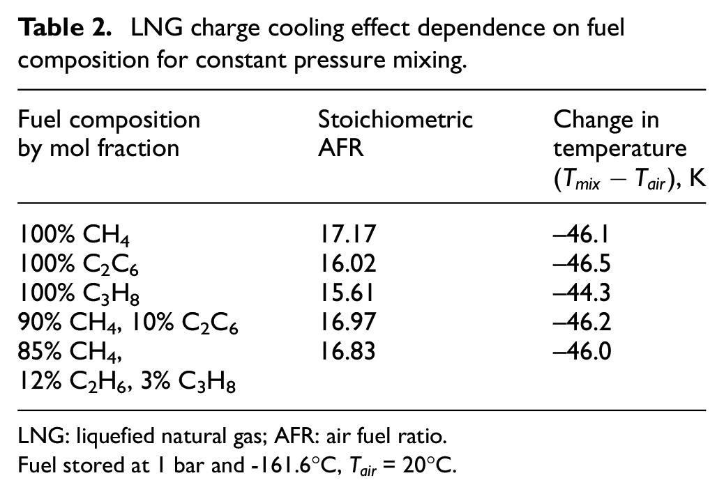
LNG: liquefied natural gas; AFR: air fuel ratio.
Fuel stored at 1 bar and -161.6°C,
Ideal engine cycle
This section explores the implications of the predicted charge cooling potential of the various mixture preparation strategies listed in Table 1 by considering an ideal engine cycle as a first approximation. In later sections of this article, a more detailed model is discussed.
Autoignition ahead of the flame front, commonly called ‘knock’, is a limiting factor for SI engines. The occurrence of knock is a kinetic phenomenon that cannot be captured by a simple ideal cycle; however, a suitable proxy can be used by considering the end of compression (EOC) temperature. Consider a conventional PFI-CNG which operates an Otto-like engine cycle, whose knock-limited compression ratio is
First, one can calculate that for a given SOC temperature difference (

meaning the temperature difference is amplified during compression.
By equating the EOC temperatures, a new knock-limited compression ratio can be determined in terms of the SOC temperature difference. This is given by
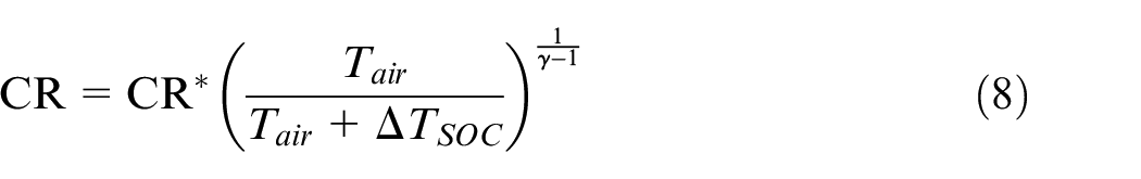
For an engine operating the Otto-cycle the specific fuel consumption
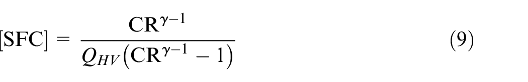
where
The ratio of SFC compared to reference case (
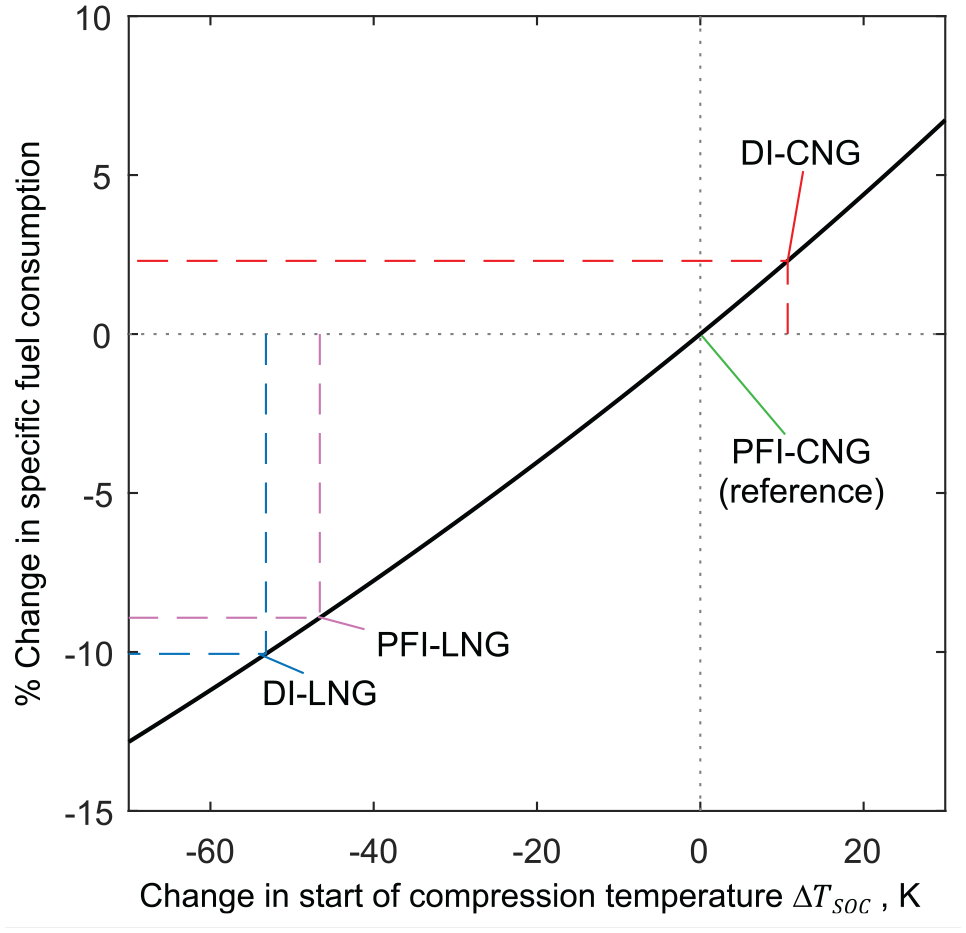
Relative change in SFC as function of
This analysis predicts the significant evaporative charge cooling enabled by LNG injection can result in substantial reductions in fuel consumption. Specifically, this suggests a 10% reduction in fuel consumption results from a DI-LNG strategy compared to conventional PFI-CNG. Another significant result is that the charge heating caused by injecting CNG into a closed cylinder can result in a ∼2% increase in fuel consumption. The temperature change predictions were taken as the values from Table 1; however, these temperature change values may be affected by factors discussed in the previous section such as tank pressure and heat transfer to the walls. This approach provides a first approximation for predicting changes in fuel consumption by compression ratio increase as enabled by charge cooling. However, using EOC temperature as a proxy for knock onset neglects the time and pressure dependence of autoignition. This limitation is addressed in the next section with a more rigorous knock model.
The ideal cycle can also provide insights into engine BMEP which can be calculated as follows
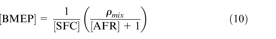
where
Theoretical fuel consumption and BMEP changes by adopting various fuelling strategies compared to the conventional PFI-CNG strategy.
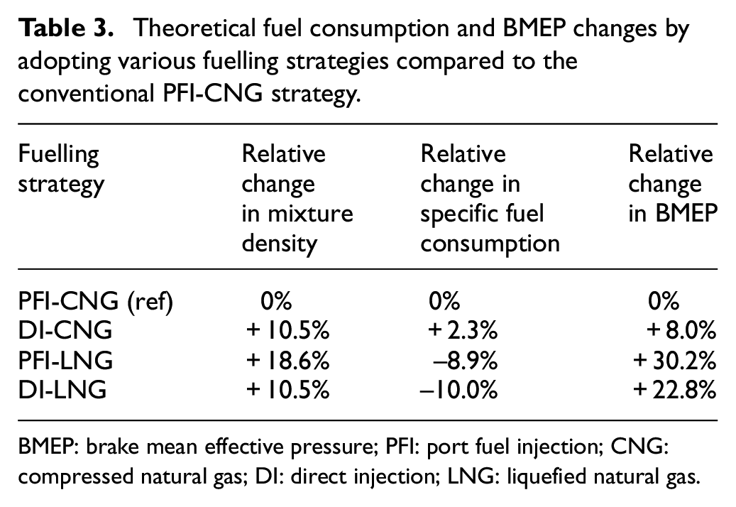
BMEP: brake mean effective pressure; PFI: port fuel injection; CNG: compressed natural gas; DI: direct injection; LNG: liquefied natural gas.
Detailed engine model
The ideal cycle analysis above provided key insights and highlights trends but is simplistic as it cannot capture essential time-dependent phenomena such as autoignition, heat transfer and NOx formation. The proceeding detailed engine model was used to obtain more rigorous performance comparisons. The dedicated fundamental engine model was constructed by the authors specifically for this purpose allowing complete control over assumptions and operating parameters. This section outlines the model details. The key fixed parameters, modelling assumptions, variables being studied and the sub-models used are defined. The purpose of this investigation not to make absolute claims about an LNG injection engine performance but is to quantify the performance of an LNG injection engine relative to a conventional PFI-CNG engine and provide fundamental reasons for the performance difference. This is done by ensuring a large amount of commonality to isolate the effects of the fuelling strategy. For this reason, minor details present on real systems that are common to all strategies have been omitted. These include, for example, the pressure drop in the intake system due to the air filter, the pressure drop in exhaust due to the TWC and piston blow-by. Also, certain governing parameters are initially kept constant for all mixture preparation strategies, including combustion duration and overall turbocharger efficiency; however, sensitivity to these parameters are investigated in the subsequent section to demonstrate the robustness of the main conclusions.
Figure 6 shows a schematic of the thermodynamic system under consideration. Ambient air is compressed and then cooled in the intercooler. The intercooler was assumed to be ideal with zero pressure drop and 100% effectiveness while being supplied with engine coolant at 325 K. NG (considered here to be pure methane) is introduced to either the cylinder (DI) or the intake (PFI). In the PFI case, the air/fuel mixture was assumed homogeneous before being inducted to the cylinder. The exhaust manifold is large compared with the engine capacity such that that
Ideal gas mixture;
Specific heats of gases are a function of temperature only;
Cylinder contents is spatially homogeneous. During combustion, when unburned and burned gas are treated separately as a two-zone model, each of the two-zones is considered spatially homogeneous;
Infinitely thin flame front.
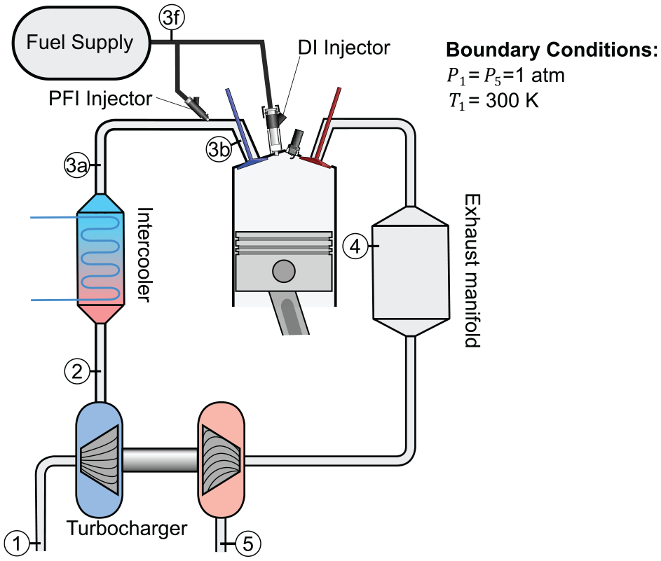
System schematic.
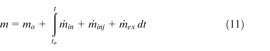
Figure 7 shows the cylinder mass and energy flows. The instantaneous total mass (
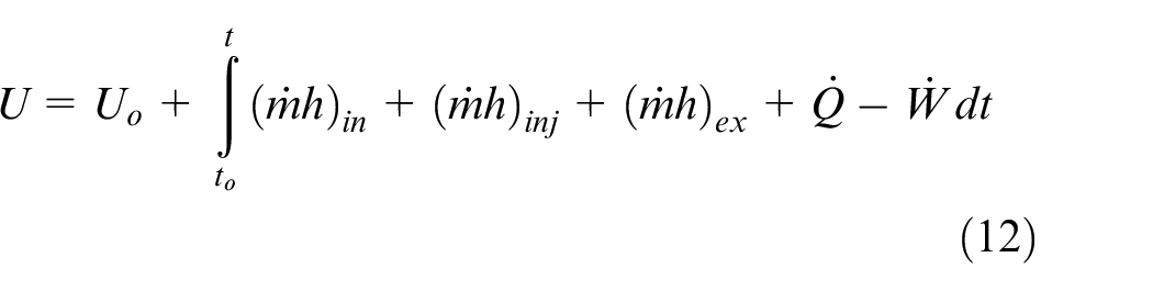
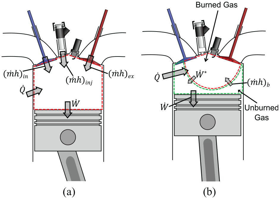
Cylinder energy flows: (a) single-zone control volume when combustion is not occurring; (b) two-zone approach during combustion.
where subscript

where internal energy

The various mass and energy flows were determined by the following sub-models. The flows through the intake and exhaust valves (
where
The fuel injection event (DI only) was initially assumed instantaneous (
Woschni’s heat transfer model was used in this analysis as described in Heywood 25 for example. The cylinder liner (150oC) and piston and cylinder head (250oC) temperatures were assumed constant and common to all strategies.
The turbocharging system was modelled using a quasi-steady approach to determine the exhaust back pressure (
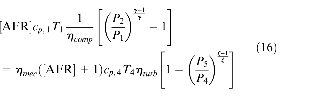
where subscripts refer to properties as indicated on Figure 6,
The friction, knock and NOx models are decoupled from the thermodynamic system. Friction was simply calculated using a correlation proposed by Chen and Flynn for

where
Knock is a key consideration in this investigation. Knock is said to occur once the Livengood-Wu integral is equal to unity, that is
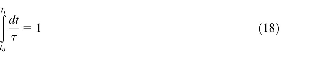
where

where
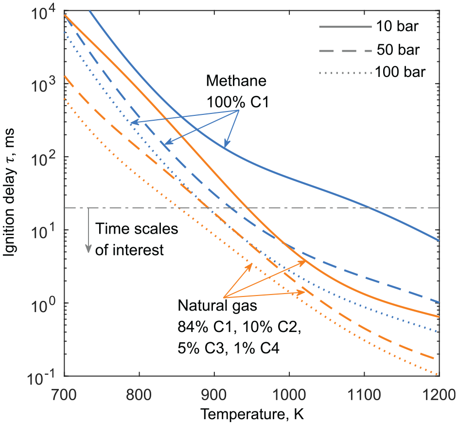
Ignition delay for stoichiometric mixture as function of pressure and temperature for pure methane and representative NG mixture.
This knock model does not directly account for local hot regions that can initiate knock earlier than expected compared to spatially homogeneous considerations. When validating the model, it was found that the model underpredicted the occurrence of knock compared to experiment and this was corrected by adding a 40 K to the unburned gas temperature to account for hot spots. Also important is the severity of knock. In the present study, an unacceptable knocking cycle was defined by satisfying equation (18) before 90% of the mass is burned. Production engines may require a greater knock safety margin and thus a more conservative definition of a knocking cycle to obtain durability, for example, this could be that the Livengood-Wu integral must be less than 0.9 when evaluated over the whole cycle. For the present study, the key feature is that all strategies are subject to the same definition of an unacceptable knocking cycle. A greater knock safety margin will therefore penalise all strategies in terms of efficiency such that relative efficiencies will remain comparable. A limitation of this approach is that different mixture preparation strategies may require different knock safety margins due to differing knock intensity characteristics.
NOx formation was modelled using the extended Zeldovich mechanism as described in Heywood 25 for example. It was assumed that NO is a minor species such that its formation does not have a substantial effect on the energy of the system meaning the heat absorbed during the reaction is neglected.
Table 4 summarises the constants used during this study. The main engine architecture is fixed, with the exception of compression ratio. In the case of LNG injection, it is assumed that there is no heat transfer in the fuel delivery system such that the fuel is delivered as a liquid. Convenient simplifications regarding injection (
Modelling constants.
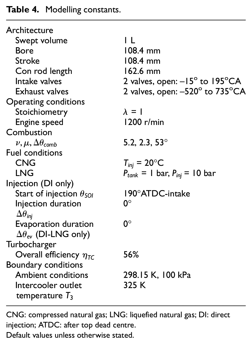
CNG: compressed natural gas; LNG: liquefied natural gas; DI: direct injection; ATDC: after top dead centre.
Default values unless otherwise stated.
Results
The effect of fuelling strategy for common engine architecture
Table 5 summarises the performance of each fuelling strategy with all other factors being equal. Combustion phasing is such that maximum brake torque (MBT) is achieved. Both strategies utilising the cooling effect of LNG result in increased MEP, decreased fuel consumption and decreased NOx emissions compared to the conventional PFI-CNG strategy. As pre-empted by the previous analysis, DI-LNG results in the best efficiency while PFI-LNG results in the greatest BMEP. Comparison of ISFC reveals the effects of heat losses. The charge heating effect of DI-CNG has a seemingly very small effect on efficiency. However, this is due to the increased trapped mass in the cylinder. While the absolute heat losses in terms of Watts show a substantial increase, the increase per unit mass in the cylinder (kJ kg-1) is small. The primary reason for the decreased BSFC of DI-CNG is the increased mechanical efficiency due to the increased MEP meaning friction is a smaller fraction of the total cycle work, that is, the efficiency of the DI-CNG strategy is aided by the fundamental engine characteristic that efficiency tends to increase with load.
Performance of fuelling strategies; intercooler outlet conditions 325 K and 100 kPa, CR 12, MBT combustion phasing.
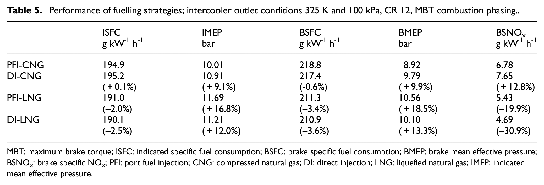
MBT: maximum brake torque; ISFC: indicated specific fuel consumption; BSFC: brake specific fuel consumption; BMEP: brake mean effective pressure; BSNOx: brake specific NOx; PFI: port fuel injection; CNG: compressed natural gas; DI: direct injection; LNG: liquefied natural gas; IMEP: indicated mean effective pressure.
Figure 9 shows a comparison of the unburned gas temperature. The fuel is injected at 190°CA for the DI strategies, just before IVC (195°CA). This minimises back flow caused by CNG injection or likewise additional inflow cause by LNG injection such that they operate as the intended ‘closed-valve’ injection strategy while still being injected close to BDC. The injection of LNG or CNG can be seen as a rapid temperature change where cooling and heating occur respectively. The substantial evaporative cooling of LNG is evident while CNG causes a small heating effect. In addition, the significantly lower temperature of the PFI-LNG strategy during the intake stroke is shown while the other strategies are inducted at or near to intercooler outlet conditions. The gas temperature during the intake stroke is marginally greater than the intercooler outlet temperature due to mixing with trapped, residual exhaust gas. Compression of the unburned gas increases the temperature approximately in proportion to the initial temperature at near-BDC and therefore increases the temperature differences between the strategies. The peak unburned temperature difference is significant, reaching ∼100 K difference between DI-CNG and DI-LNG. By reference to Figure 8, it can be seen that a reduction in unburned gas temperature of 100 K can lead to a factor of ∼7 increase in ignition delay, contributing to substantially increased knock resistance.
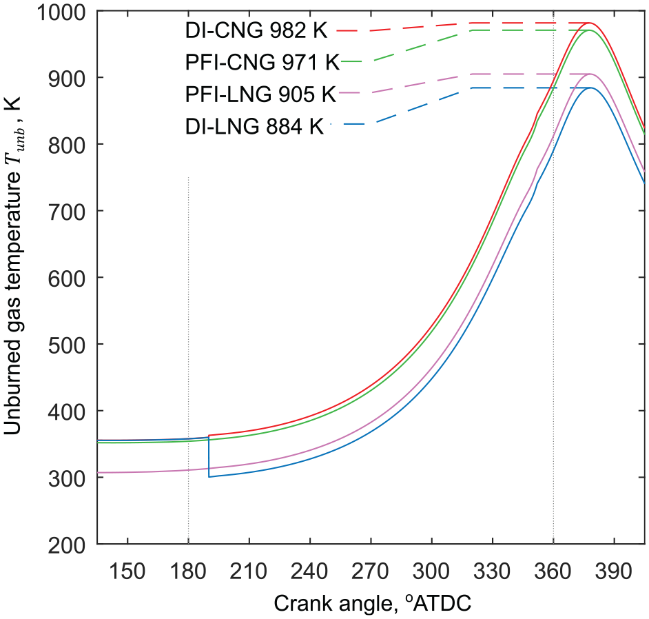
Unburned gas temperatures vs crank angle; intake conditions 325 K and 100 kPa, CR = 12, MBT combustion phasing.
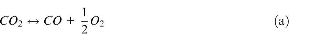
Figure 10 shows burned gas temperatures for the four strategies. The peak temperature difference between DI-CNG and DI-LNG is reduced to ∼50 K compared to the unburned gas temperature difference. Simple considerations suggest that the temperature difference of the burned gas would be the same as the unburned gas, however, high temperatures are significantly attenuated by the increased heat capacity of the mixture and increased formation of high energy chemical bonds through dissociation of CO2, for example. This means more energy is needed to raise the temperature of the gas. The true effect of LNG injection and evaporative cooling is to reduce the energy (internal energy) of the mixture compared to CNG injection. This in turn lowers the compression work required and therefore significantly lowers the energy of the mixture towards TDC. Operating with DI-LNG reduced compression work by 19% compared to conventional operation. At low temperatures (unburned gas), this energy difference manifests as a large temperature difference, however, at high temperatures (burned gas) this energy difference appears as a lower temperature difference due to increased heat capacity and dissociation reactions.
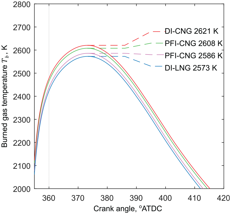
Burned gas temperatures vs crank angle; intercooler outlet conditions 325 K and 100 kPa, CR = 12, MBT combustion phasing.
The difference in burned gas temperature histories results in different NOx emissions as shown in Figure 11. The exponential dependence of reaction rate on temperature means minor differences in temperature can results in a significant reduction in engine-out NOx when kinetics are considered. Following conversion to specific emissions, a DI-LNG and PFI-LNG strategy result in a 31% and 20% reduction, respectively, in NOx emissions while simultaneously increasing engine torque and efficiency. In contrast, DI-CNG results in a 13% increase in NOx.
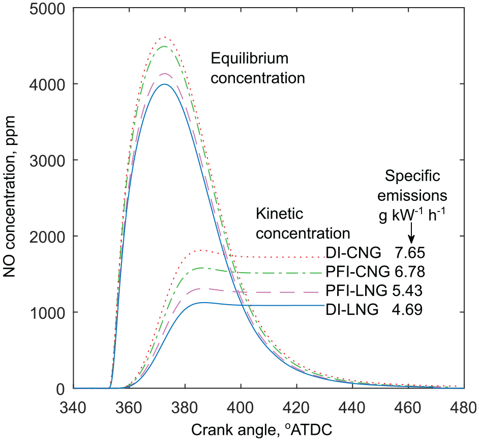
Equilibrium and kinetic NO concentrations vs crank angle for various fuelling strategies; intercooler outlet conditions 325 K and 100 kPa, CR = 12, MBT combustion phasing.
The effect of increasing knock limited compression ratio
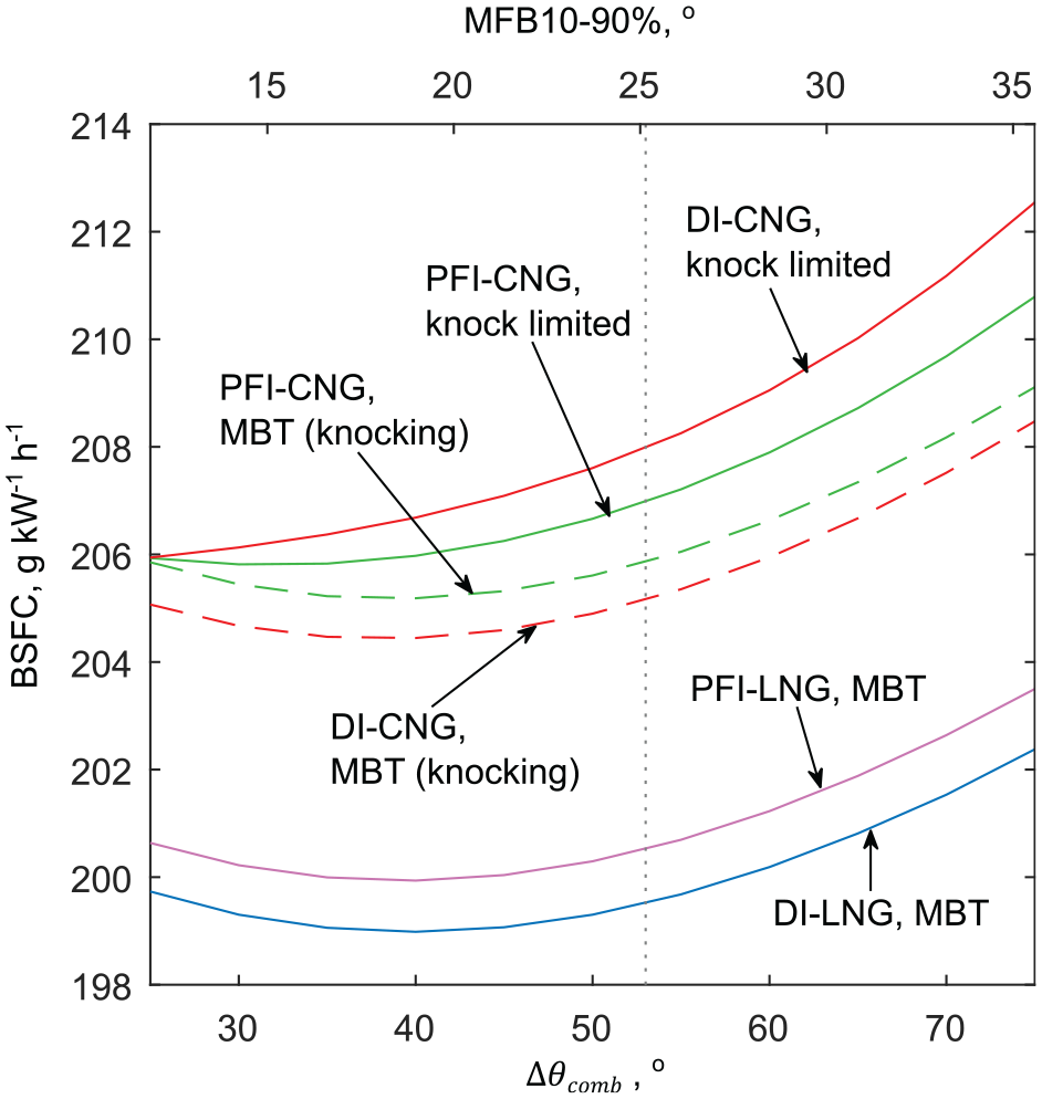
The benefits of LNG evaporative cooling in terms of efficiency, torque and NOx emissions have been demonstrated without alterations to engine architecture. However, the knock suppressing characteristics of LNG evaporative cooling allow the compression ratio to be increased. Figure 12 shows one of the key results of this investigation, the effect of increasing compression ratio on fuel consumption for different fixed intake (intercooler outlet) conditions corresponding to a medium and high load condition. It is assumed the charge cooler is ideal and can cool the intake air to 325 K under all conditions. It is worth noting that if intake temperatures increase with load due to decreased residence times and increased cooling power required in the charge cooler, then knock is more likely and the benefit of LNG evaporative cooling will be even more significant. MBT combustion phasing is maintained where allowed by knock-free operation, but the combustion phasing is progressively retarded at higher compression ratios to prevent knock. The dashed lines are a theoretical extension of MBT timing if knock considerations are ignored.
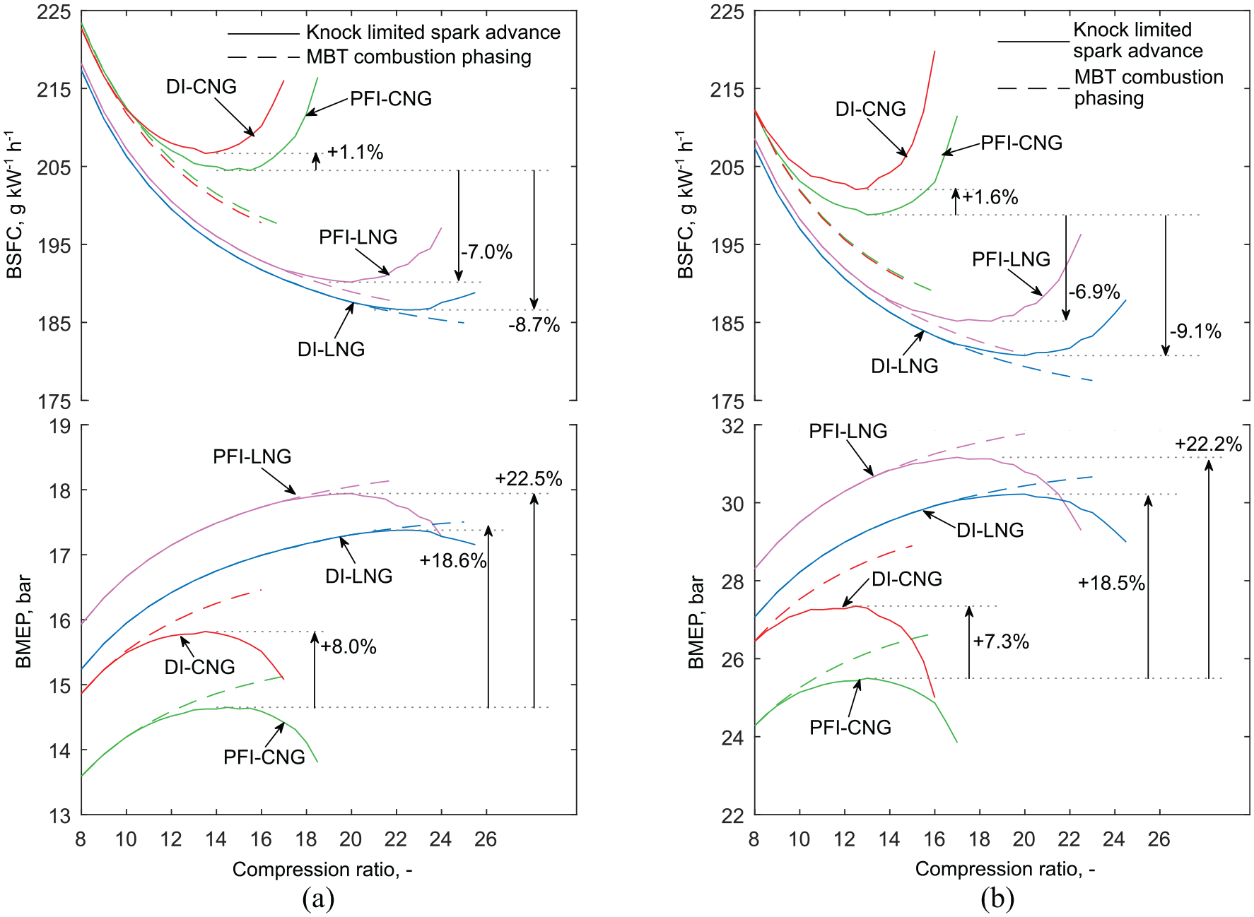
BSFC and BMEP vs compression ratio for various fuelling strategies at different intake pressures (a) 150 kPa and (b) 250 kPa.
Again, it is shown that for a given compression ratio and MBT combustion phasing, LNG injection cools the mixture resulting in lower heat losses and reduced fuel consumption on the order of ∼3%. For each fuelling strategy and intake pressure, an optimum compression ratio emerges. This optimum compression ratio is reduced at higher intake pressures (higher loads). The optimum compression ratio is higher for fuelling strategies that have lower unburned gas temperatures as indicated by Figure 9 and therefore fuel consumption is lower. As the compression ratio is increased from a low value, knock is first encountered for DI-CNG due to the compressive charge heating effect. The combustion phasing is retarded to allow knock-free operation at higher compression ratios. Initially, fuel consumption continues to decrease as the efficiency improvement from increased compression ratio outweighs the efficiency reduction from non-optimal combustion phasing until the optimum efficiency in reached. For the LNG injection strategies, knock is not encountered until much higher compression ratios due to the charge cooling effect. This results in a consistent and significant change in fuel consumption for each of the strategies compared to PFI-CNG of approximately +1.3%, -7.0%, and -8.9% for DI-CNG, PFI-LNG and DI-LNG respectively, when the optimum efficiency point is selected. The increased knock susceptibility and thus reduced fuel efficiency for the DI-CNG strategy is significant since this is seen as an attractive area of future development for NG engines. Injecting CNG into a cylinder with the valve closed can be likened to increasing the effective compression ratio, with the CNG expansion into the cylinder compressing the air. The effective compression ratio is increased, knock susceptibility is increased, yet the expansion ratio remains the same resulting in a negative outcome for efficiency. Figure 12 also shows the BMEP of the various fuelling strategies that result from a combination of fuel efficiency and volumetric efficiency changes. PFI-LNG results in the greatest BMEP (+22.5%) due to the significantly increased intake charge density. This is followed by DI-LNG (+18.5%) and DI-CNG that results in approximately a 7.7% increase over PFI-CNG.
Performance comparison with engine load
Figure 12 demonstrated the reduction in optimum compression ratio with engine load. However, ignoring the practical possibility of variable compression ratio (VCR), a single optimum compression ratio must be selected for all engine loads. Figure 13 shows the relative changes in fuel consumption for various fuelling strategies and compression ratios for a typical full-load range. The reference condition was selected as the conventional PFI-CNG strategy at a compression ratio of 12. This is such that there is little to be gained in terms of efficiency by increasing the compression ratio and allows a margin for factors which may increase knock susceptibility such as ageing of the LNG fuel.
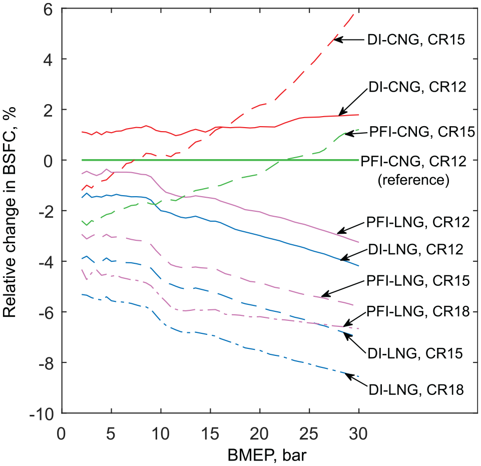
Relative change in BSFC of various engine configurations compared to a conventional PFI-CNG engine with CR = 12.
Comparing the four fuelling strategies at the same compression ratio, it can be seen that DI-CNG leads to increased fuel consumption and LNG injection leads to reduced fuel consumption, with DI-LNG achieving the lowest fuel consumption. At low loads, DI-CNG results in a relatively consistent ∼1.2% increase in BSFC.
This is due to increased pumping losses, that is, a lower intake manifold pressure for a given load due to the fact that the CNG is injected after IVC. As the load is increased, the fuel consumption penalty is increased ending at +1.8% at 30 bar. This is due to increased knock susceptibility and thus a greater spark retard required compared to PFI-CNG. As with DI-CNG, both PFI-LNG and DI-LNG suffer from greater pumping losses at low loads because of the greater charge densities and therefore lower intake pressures required. However, this is countered by reduced heat losses to give a net fuel consumption reduction of ∼1.5% for DI-LNG and ∼0.5% for PFI-LNG. As the load is increased, the reference strategy (PFI-CNG) must retard the spark to avoid knock, this occurs at approximately 10 bar BMEP in this case. However, both LNG strategies with a compression ratio of 12 are able to operate knock free at MBT timing for the full load range. This is the reason the fuel economy benefit increases significantly with load, ending at -4.2% for DI-LNG and -3.3% for PFI-LNG.
If the compression ratio is increased for both CNG strategies, this results in a negative impact on fuel consumption at high loads, but a positive impact at low loads. However, for the LNG strategies, the compression ratio can be increased to give a fuel economy benefit at all loads. Increasing the compression to 15, DI-LNG can again satisfy the full load range at MBT timing while PFI-LNG required spark retard past 22 bar. At a compression ratio of 18, the spark retard of PFI-LNG required for a given load is comparable to PFI-CNG at CR 12 which causes the levelling-off of the efficiency improvement line at higher loads. However, DI-LNG maintains much closer to optimal combustion phasing at high loads, maintaining MBT timing up to 21 bar. Increasing the compression ratio from 12 to 18 allows an efficiency improvement of ∼5.5% at low loads and up to 8.6% at high load for a DI-LNG strategy compared to PFI-CNG, while maintaining MBT combustion phasing for a greater load range. One may wish to increase the compression ratio further, but with diminishing returns and mechanical limits may be reached. Figure 14 shows the peak cylinder pressures for all cases.
As the compression ratio is increased the peak cylinder pressure is increased and may surpass typical mechanical limits of ∼150 bar. Generally, lower peak pressures are indicative of retarded combustion phasing and hence lower efficiency. Another disincentive to increasing compression ratio further is that more retarded combustion phasing can result in reduced combustion stability and potential misfire.
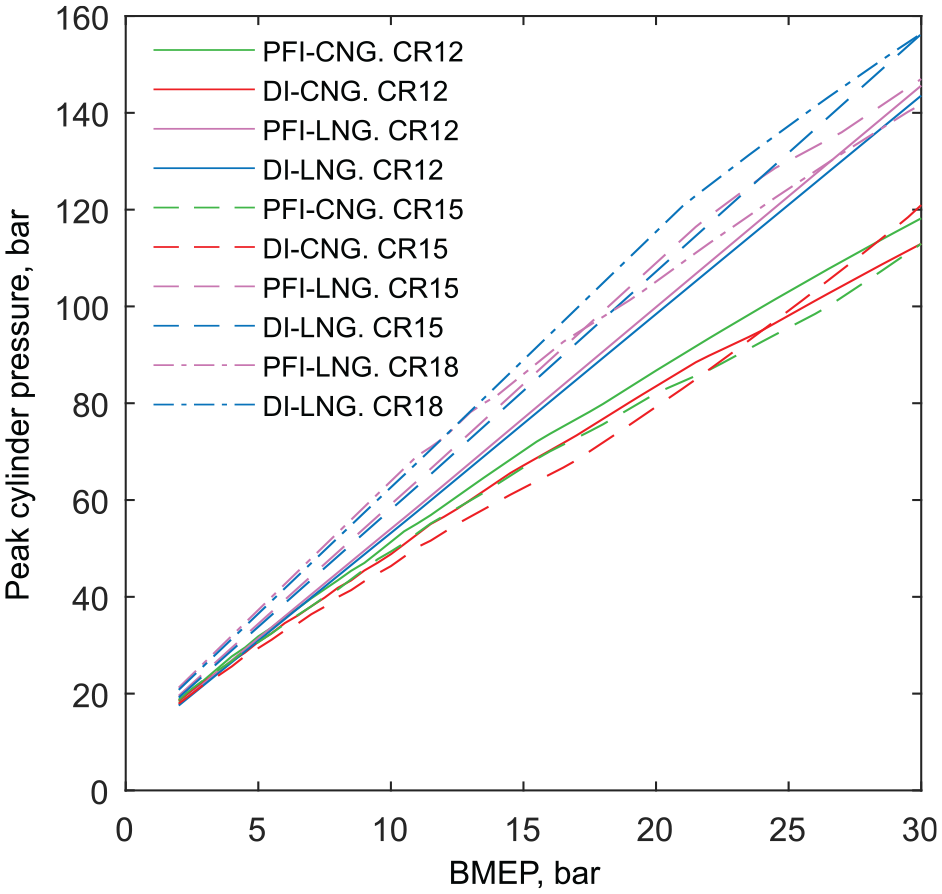
Peak cylinder pressure varying with load for various engine configurations.
The greatest efficiency improvement shown in Figure 13 was 8.6% and occurred at 30 bar BMEP for DI-LNG with a compression ratio of 18. In absolute energy terms, this 8.6% BSFC decrease corresponded to a change from 18.1 MJ kg-1 of fuel for PFI-CNG to 19.8 MJ kg-1. This means an additional 1.7 MJ of energy has been extracted from a kilogramme of LNG by direct injection of the fuel. Recalling that the thermo-mechanical exergy contained by the LNG was ∼1 MJ kg-1, this means a dedicated device for extracting energy from the gasification of LNG such as a Rankine cycle could, as best, harvest 1 MJ kg-1. Importantly, it has been demonstrated that the synergy between the IC engine and LNG fuel results in greater efficiency than the theoretical maximum of the individual parts (e.g. a CNG IC engine, plus a separate device for thermomechanical exergy harvesting). This is true even before the efficiency of the for thermomechanical exergy recovering device is considered.
NOx emissions trends are shown in Figure 15. For a given compression ratio, DI-CNG increases NOx emissions by a few percent. PFI-LNG and DI-LNG decreased NOx by up to ∼25% and ∼35%, respectively, at low load. As the load increases, the NOx reduction decreases. This is because as the load is increased beyond ∼10 bar, the reference strategy (PFI-CNG) requires retarding of combustion phasing which is known to decrease NOx emissions. This trend is therefore a consequence of optimising combustion phasing for efficiency. As shown in Figure 16, it is possible to obtain more significant NOx reductions at the cost of efficiency. For example, NOx reduction for DI-LNG can be doubled from 20% to 41% if comparing at the same fuel consumption compared to the optimum efficiency case for the 15 bar load selected. Figure 16 shows that the evaporative charge cooling shifts the fuel consumption/NOx trade-off curve towards the ideal origin (0,0).
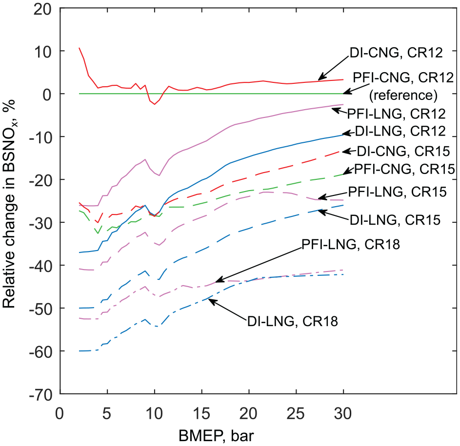
Relative change in engine-out BSNOx of various engine configurations compared to a conventional PFI-CNG engine of CR = 12.
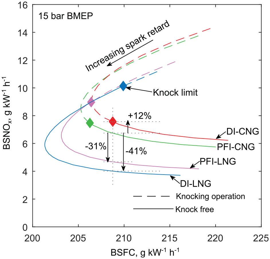
NOx emissions/fuel consumption trade-off by varying combustion phasing at constant load, CR = 12.
Figure 15 also shows that NOx emissions decreased with compression ratio. This is for two reasons; first, as the compression ratio increased, the optimum spark timing was more retarded, meaning there was little difference in peak combustion temperatures. Second, there was less time spent at high combustion temperatures as the compression ratio increased due to more rapid expansion, meaning there was less time available to kinetically form NOx. The net result of LNG injection enabled charge cooling and compression ratio increase was a net NOx reduction of 45%–60% for a DI-LNG fuelling strategy.
Performance sensitivity
The preceding performance predictions are contingent on the constants used in Table 4. The purpose of this section is to determine how these performance predictions are affected by changes to key parameters and therefore determine the robustness of the conclusions made.
Turbocharger efficiency
The previous results assumed a constant turbocharger efficiency for all flow rates and boost pressures. Figure 17 shows BSFC sensitivity to overall turbocharger efficiency (
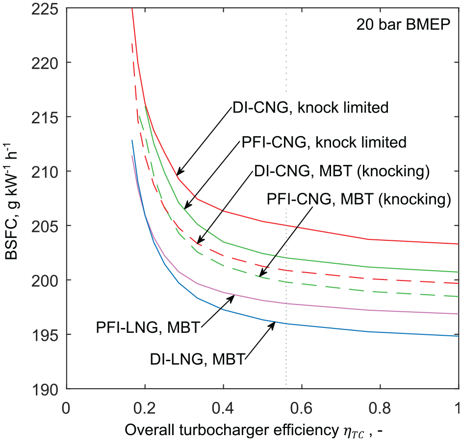
Fuel consumption versus overall turbocharger efficiency at constant load (20 bar), CR = 12.
Realistic turbocharger efficiencies for most operating points are likely lower than 56% as used in the previous results. Figure 17 reveals that lower turbocharger efficiencies increases fuel consumption of PFI-CNG more than all other strategies, so only increases the fuel consumption benefit of LNG injection strategies compared to conventional PFI-CNG. It also shows that there are conditions where DI-CNG could give an efficiency improvement over PFI-CNG. If the turbocharger is operating at a particularly poor efficiency, it is possible that the reduced boost pressure required by operating DI-CNG can overcome the efficiency penalty due to the charge heating effect. However, the direction of travel should be towards greater turbocharger efficiencies and this reduces the appeal of DI-CNG.
Combustion rate
The previous analysis assumed a constant rate of combustion. In reality, the burn rate will depend on mixture temperature and pressure, which in turn depend on the fuelling strategy and compression ratio.
Figure 17 shows performance sensitivity to the combustion rate parameter
The laminar burning velocity is a key parameter in terms of predicting combustion. Various studies have shown that the laminar burning velocity (
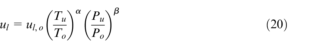
where subscript
It can be assumed that the unburned gas in the cylinder undergoes isentropic compression and expansion, where the compression or expansion is due to a combination of piston motion and burned gas expansion. Therefore, the unburned gas properties at any point in the cycle can be determined from the properties at IVC depending on the volume ratio (
Assuming ideal gas and substituting expressions for
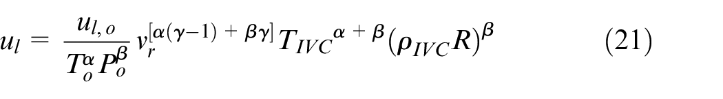
For the desired purpose of direct comparison of the various fuelling strategies, a high degree of commonality can be assumed. For a given engine load, the trapped mass in the cylinder and therefore
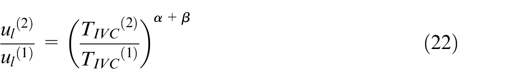
This shows the relative laminar burning velocity depends only on the temperature at IVC. By reference to Table 1, the predicted change in

where
Fuel consumption sensitivity to combustion duration for constant intake pressure
Further to this conclusion, the LNG evaporative cooling enables compression ratio to be increased which tends to increase the mass burn rate. Substitution of equation (21) into equation (23) results in the mass burn rate as
which means that the ratio of mass burn rate between two strategies for a given load approximately equals
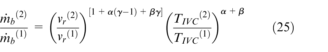
where the exponent
Evaluating
LNG evaporation rate
Previously, the LNG evaporation and the resulting cooling effect was assumed instantaneous. However, this raises the question: what impact will a slower evaporation process have on DI-LNG engine performance? This section answers this question from a thermodynamic perspective. While evaporation rate also carries implications for the mixing quality, this is not specifically investigated here.
The evaporation rate of a stationary droplet when the environment is at a temperature much greater than the liquid’s boiling point is given by Spalding 31
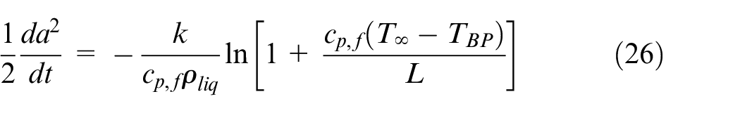
where
This results in the evaporation time of the droplet being proportional to the initial diameter squared, the well-known d-squared law often used for evaporating fuel droplets. The spray evaporation was modelled by considering a spray of uniform droplet size using a two-zone approach where the homogeneous gas phase and the fuel liquid phase are separate. The injection of the liquid causes a small (near-negligible) amount of compression prior to evaporation. The fuel then evaporates in accordance with equation (26) where
Figure 19 summarises the effect of finite evaporation times on unburned gas temperatures. As previously discussed, instantaneous evaporation results in an 86 K decrease in peak unburned temperature as the initial temperature drop is amplified during compression. Instantaneous evaporation is desired to reduce compression work for the entire compression stroke, resulting in amplification of the temperature drop during compression. More precisely, constant volume evaporation is desired. The relative change in volume in the early stages of the compression stroke is sufficiently small such that constant volume evaporation is closely approximated despite relatively long evaporation durations. For this reason, there are only minor differences in the peak unburned temperature predictions depending on evaporation rate. Although there are significant differences in the temperature traces soon after injection, the temperatures traces closely approach a common value once evaporation is complete. It can be seen that a slow evaporation rate (
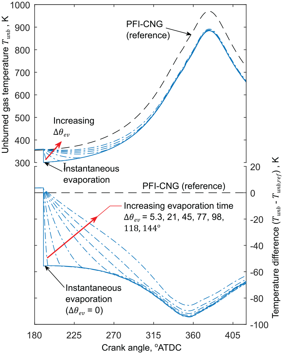
Unburned gas temperatures variation with crank angle. Comparison between PFI-CNG and DI-LNG with various evaporation rates.
Defining evaporation duration in terms of crank angle as the difference between injection and complete evaporation, an evaporation duration of 98° reduces the peak unburned gas temperature drop from 86.4 K in the instantaneous case to 84.7 K. A small finite evaporation time (<60°) can actually reduce temperatures compared to an instantaneous evaporation event due to reduced charge heating from the cylinder walls near BDC. Provided the fuel evaporates in accordance the d-squared law and evaporates before ignition, there is relatively little change in the temperature predictions due to evaporation duration and therefore little difference in NOx predictions. A slow evaporation rate leads to greater cylinder pressures in the early stages of compression and consequently increases compression work resulting in decreased fuel efficiency. The impact of this on fuel efficiency is shown in Figure 20. A relatively long evaporation duration of 100°CA increases BSFC by ∼1%. This therefore slightly diminishes the efficiency benefit of DI-LNG compared to PFI-CNG, but not enough to overturn the major conclusion that DI-LNG results in significant fuel efficiency benefits.
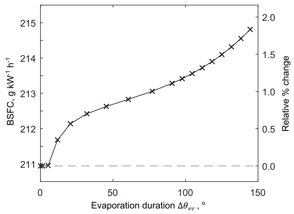
Variation in fuel consumption with evaporation duration (
CNG injection duration
In the case of DI-CNG, the injection event may be limited by the sonic velocity through the injector nozzle. Previously, the injection event was assumed instantaneous (i.e.
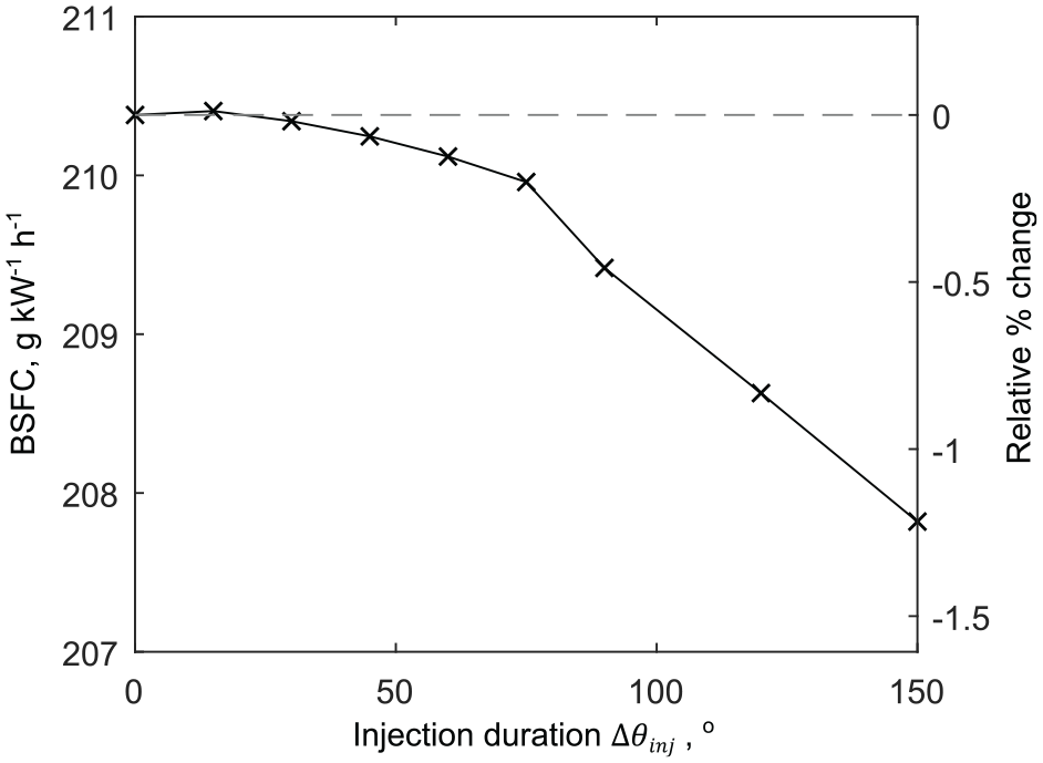
Variation in fuel consumption with injection duration for DI-CNG engine at constant load 15 bar BMEP, CR = 12,
Conclusion
This study has presented new important findings regarding engine performance in terms of BMEP, BSFC and BSNOx comparing four fuelling strategies available to LNG vehicles (PFI-CNG, DI-CNG, PFI-LNG, DI-LNG) in the context of a homogeneous-charge, spark-ignited, stoichiometric NG engine. This was accomplished using a dedicated, fundamental, thermodynamic model. From this analysis, the following important conclusions can be drawn:
LNG thermomechanical exergy presents an untapped resource of potential work available on all LNG vehicles. A dedicated 100% efficient heat engine can at best harvest ∼1 MJ kg-1 of LNG.
The charge cooling potential of LNG is greatest when directly injected into the cylinder after IVC resulting in minimum cycle temperatures and maximum efficiency. The charge cooling potential is primarily dependent on the LNG storage pressure with lower storage pressures achieving maximum cooling as well as greatest fuel density. Fuel composition and pumping work (if used) have a small effect on charge cooling. The greatest charge density is achieved for PFI-LNG, which enables the highest BMEP of the four strategies. Direct injection of CNG into a closed cylinder (DI-CNG) can overcome the problem of fuel displacing air in the intake during PFI-CNG operation but will increase cylinder temperatures and will likely marginally decrease efficiency.
The LNG evaporative cooling reduced heat losses and enables advancing combustion phasing and/or increasing compression ratio. For a given intake pressure it was found DI-LNG simultaneously enabled -8.9% BSFC, +18.5% BMEP and -51% BSNOx. Similarly, PFI-LNG enabled -7.0% BSFC, +22.5% BMEP and -37% BSNOx. However, DI-CNG resulted in a negative outcome for fuel consumption and emissions with +1.3% BSFC and +16% BSNOx, while achieving +7.7% BMEP.
The benefits of LNG evaporative charge cooling are greatest at high load where operation is knock limited. At low load, the increased charge density results in increased pumping losses which diminish the efficiency improvement. It was found that at high load (30 bar) for DI-LNG the additional mechanical work obtained through LNG evaporative cooling was +1.7 MJ kg-1 which is greater than the thermomechanical exergy of the LNG.
The performance predictions from the detailed engine model agreed with and refined the performance predictions from ideal cycle analysis.
The obtained conclusions were found to be robust to changes in key parameters. Changes to factors such as turbocharger efficiency, combustion duration, evaporation duration and injection duration have a minor effect on the exact performance improvements of DI-LNG and PFI-LNG but do not change the overall outcome of reduced fuel consumption and reduced NOx emissions. In some cases, changes to these parameters increased the predicted benefit of LNG injection.
These conclusions are grounded in fundamental thermodynamic considerations. However, it should be noted the present model is not designed to account for spatial phenomena such as mixing, charge motion and temperature gradients. Each fuelling strategy may carry implications for mixing quality and in-cylinder turbulence that the present model cannot identify. These effects are currently under investigation by the authors. Other factors that may require further investigation include implications for the piston lubricating oil film. It is expected that these factors are secondary and will not overturn the major conclusions. Finally, this study assumed that the LNG fuel can be delivered to the engine in a low enthalpy state, at or near to the storage tank conditions, requiring minimal heat transfer in the fuel delivery system. The conclusions of this study provide the motivation to address this practical challenge.
Footnotes
Appendix 1
Acknowledgements
Declaration of conflicting interests
The author(s) declared no potential conflicts of interest with respect to the research, authorship, and/or publication of this article.
Funding
The author(s) received no financial support for the research, authorship, and/or publication of this article.