
Abstract
This work aims to investigate the wear mechanics of a conventional abradable material (Metco 320) used for compressor sealing between the blade and surrounding casing, backed by an open-cell metallic foam substrate, determining whether the use of the foam backing material results in a rub compliant liner. Testing is carried out on a scaled-down high-speed rig to create engine-like conditions to understand how the capped metallic foam deforms and compacts. The metallic foam substrates are NiCr-based alloys, and this study compares the effects of abradable cap hardness, incursion rate and foam pore size on the behaviour observed. In situ measurement techniques have been utilised to observe the wear mechanic present, with these including force measurement as well as high-speed imaging. Softer capped foams were seen to show higher levels of compaction and compression, forming a concentric track in response to the rub event, when in comparison to a harder cap. Similarly, faster incursion rates performed best in terms of material actuation, with this linked to the large energy input per strike of the blade. Pore size showed a significant impact ability of the hybrid system to accommodate the rub, where coarse flexible foams performed better than fine stiff ones.
Introduction
Seals in aero engines serve many purposes. However, two main functions exist, which are to restrict leakage out of the system and furthermore to prevent contaminants from entering the system. 1 One sub-class of seals are abradable materials, which are commonly used between rotating and static components to allow for good clearance control and increased performance.2–4 With current abradable sealing materials and technologies, even under optimum conditions, performance can vary due to inconsistencies within the material microstructure, resulting in material adhering to the blade and grooving of the liner. Significant damage such as this to the engine casing can cause losses in blade tip aerodynamic efficiency, and in turn impact airline companies financially in terms of increased fuel consumption. 5 Resin-filled metallic foams have previously been shown to actuate a more desirable wear mechanism as they compact with low forces, resulting in a concentric seal path with minimal blade wear. 6 Given the temperature limitations of resin-filled metallic foams, this study seeks to investigate whether similar improvements in abradability performance can be achieved by over-spraying a conventional abradable material onto a metallic foam substrate.
Abradable seal materials are used in both the compressor and turbine stages of the engine, and are typically worn in by rotating blades during engine pass off. Whilst also to a degree true for the turbine, in particular abradable coatings are applied in the compressor to decrease clearances to levels difficult to achieve by mechanical means alone. Such seals allow cold clearances to be reduced, whilst at the same time providing a sacrificial layer on the stationary surface to prevent blade damage, should the two bodies come into contact during service. Additionally from a manufacturing perspective, good sealing can also still be achieved in operation, whilst accommodating common shroud or casing out-of-roundness as well as rotor misalignment. 7 Such clearance reductions are also achieved at relatively low cost, and come with minor engineering implications for the service fleet, where current operations demand enhanced heat rates and reduced costs. As well as being important in terms of efficiency, for compressor stages such coatings also offer a thermal barrier benefit, increasing component life. In particular, they decrease alloy temperatures at constant operating conditions, which in turn decreases the usage of cooling air necessary within the compressor stage. 8 With the absence of abradable seals, a cold clearance between the blade and shroud must be large enough to prevent significant contact during the operation of the engine. In turn engine efficiency is reduced.
Typical coating requirements for clearance control applications in aero-engines include resistance to wear, erosion, corrosion and oxidation.9,10 Often Wc-Co coatings are used, which have good wear-resistance, critical for compressor component materials. 11 However, such coatings can only be used for temperatures up to 580°C, where the limit becomes oxidation of the WC phase when this temperature limit is exceeded. 12 Current compressor abradables such as AlSi powders are sprayed onto the casing, and are usually deposited through the use of high-velocity combustion or plasma spray techniques.13–15 Such coatings, as well as being cut also compact, leading to unfavourable wear events when their capacity to further compact is exhausted. Given this, a clear need exists to create more compliant coatings with a greater capacity for compaction.
Abradable linings manufactured by thermal spraying have been extensively investigated by Delebarre and others, where interaction forces have been measured to better quantify the wear mechanics and behaviour of such coatings.16–20 In addition, previous studies by Fois 21 and Bounazef et al. 22 have further developed methodologies to effectively test abradable samples and prove their feasibility for clearance control applications. This study makes use of such criteria and methods to understand the role of capped metallic foams for compressor stage sealing. The tests conducted use titanium blades which are mounted to a rotating disc positioned directly above a stage. On the stage, the abradable sample is attached and held in place where it is raised to enable a contact between the blade and abradable similar to that in an aero-engine. Tests are conducted with a blade tip speed of 100 m/s, with this being a test condition where engine-representative wear mechanisms exist and have been previously investigated. 21
For the samples used in this study, the top surface consists of a layer where the thermally sprayed abradable has penetrated the metallic foam to create a hybrid material. The thermally sprayed abradable powder is an AlSi–hBN alloy which is currently used as an abradable in conventional compressor stages of an aero-engine. A metallic foam is then used as a base phase to encourage collapse and deformation of the abradable when rubbed, to form a concentric arc, which in turn accommodates the blade path. In situ, force and temperature measurements are obtained upon contact with every blade strike, to gain insight into the abradability behaviours over a range of incursion conditions representative of those seen in an engine.
Materials and methods
The testing for this project is conducted using a scaled-down rig at the University of Sheffield, and described extensively in Tong et al. 10 As shown in Figure 1, the rig consists of a disc mounted to a spindle, within which both a test blade and dummy blade for balancing are mounted. The spindle is then controlled via an inverter, enabling the disc to be rotated at a constant prescribed speed. An abradable sample is mounted onto a z-axis microscope stage directly below the disc, and can be incurred into it once rotating at a set rate. Upon starting the test, the spindle is first rotated to the desired speed, and the stage is then driven up towards the rotating blade with a set incursion rate to mimic flight conditions. In this way a high-speed contact similar to that found in the engine is carried out at ambient conditions. Located below the sample stage is a dynamometer which measures the forces in the normal and tangential directions with respect to the blade face. A pyrometer is also used to measure the temperature in the contact, and is focussed at the centre of the rub track. In addition to this setup, a high- speed imaging system is also used. This instrumentation enables a visual representation of the material behaviour as well as some insight into the compaction/deformation mechanisms seen in the substrate due to the forces resulting from the blade strike. The rig itself is LabView controlled and all the data is recorded through an internal programme where the appropriate parameters previously mentioned are recorded. The measurement system allows for constant monitoring of the interaction between the blade and abradable on a pass by pass basis, with the set up more extensively explained in Fois et al., 21 aside from the high speed imaging system which will be further detailed below.
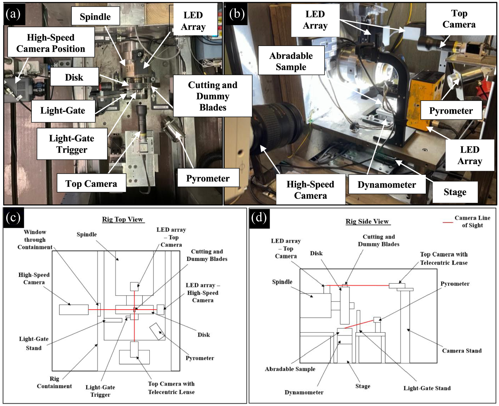
(a) Rig top view, (b) rig side view, (c) schematic of rig showing top view and (d) schematic of rig showing side view.
As noted, high-speed imaging is used to capture the blade-to-substrate interaction. The camera used is a Phantom VEO-E 340L high speed imaging device, and is able to capture up to 72,000 fps at a resolution of 800 fps at 2560 × 1600. The camera is positioned outside of the test rig containment, and focussed on the rub track via a small viewing window. In order to ensure appropriate illumination of the test set up, a high-power LED is positioned by the sample to provide lighting during a test. Phantom camera control (PCC) software is used to capture images at a frame rate of 10,000–20,000 (dependant on the test duration), with triggering of the set up achieved through synchronisation with the aforementioned LabVIEW programme. In combination with the force and temperature measurements, where any events of interest occur, the imaging system is then used to investigate the nature of the blade – abradable interaction at that point and provide a record of the wear event present.
Figure 2 shows a typical blade (A) and abradable sample (B) used in this study. The test blade shown on the left of Figure 2(a), manufactured from Inconel 718, and represents the standard test blade used at all times in this study. On the centre and right of Figure 2(b) and (c) are the as manufactured and post-processed abradable samples, where on the as-manufactured sample the thermally spayed abradable cap is clearly visible on top of the foam. As highlighted in the figure, the foam sample has been ground prior to testing, and this process will be detailed in the following section.
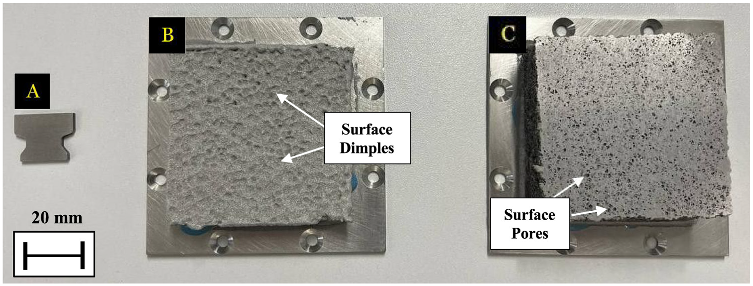
(a) Blade with, samples, (b) manufactured foam and (c) ground foam.
The metal foam material used as the substrate is commercially sourced, and is manufactured by Recemat BV under the trade name NC1116. It is manufactured through a heat treatment process, where a nickel precursor material is unwound. This process involves the application of an initial binder solution to first coat the material, followed by another coating of high alloy powder. Next a heat treatment process is employed, consisting of steps of de-binding and sintering. The de-binding phase of the process involves removal of the initial binder solution from the metallic structure surface, before sintering enables the high alloy powder to diffuse effectively into the metallic ligaments of the foam structure, creating a homogeneous and uniform material microstructure, in this case in the form of the purchased sheet. In order to prepare the test specimens, foam samples are cut to size from the sheet and glued to a stainless steel backing plate using epoxy resin glue. Following this step, Metco320 powder is thermally sprayed onto the top surface of the foam, using conventional spraying parameters to achieve a hard and soft abradable cap, where previous studies have shown a reducing elastic modulus as the abradable hardness drops. 23
All of abradable samples in this study are ground back to form a thin top surface cap (Figure 3), where grinding is ceased when the ligands of the foam are just exposed. Grinding was undertaken on an Ecomet Buehler grinding machine using 240 grit paper. This approach has been taken to ensure a uniform sample condition was achieved, and in turn investigate whether the abradable sample is able to collapse and compress in response to the incursion event. Additionally, given the penetration of the abradable material into the foam, should grinding back not be performed, the cap would be too thick and unlikely to deform when rubbed.
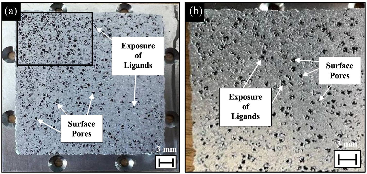
Ground cap surface macrostructure (a) and surface enlargement and identification of key features and surface finish (b).
Figure 4 shows cross sections of the achieved abradable cap, with the backscattered image shown recorded using a TM3030Plus electron scanning microscope at 40 times magnification. As shown in the figure, the abradable material can penetrate up to 1.7 mm into the foam. However, it is also notable that there are many inconsistencies in penetration due to different pore locations within the metallic foam matrix. Areas of infiltration have been labelled, and furthermore the cap thickness can also be clearly identified. The two examples shown in Figure 4 are different samples which suggest that when grinding back there is consistency within the extent to which samples are ground. A range of thicknesses have been measured across the cross section for an average of 0.34 mm penetration depth.
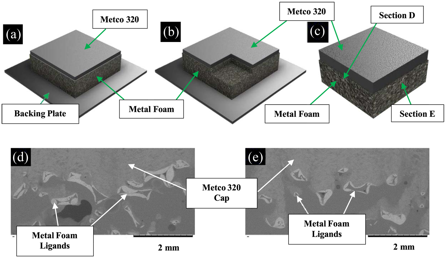
Schematic of (a) showing a typical abradable capped foam where (b) showing the remains once partition (c) has been taken to observe representative cross sections (d) and (e).
Finally, Table 1 shows the test matrix, where for all metallic foam samples it should be noted that they were sprayed with the same batch of powder for consistency in microstructure. In each case, an initial cap thickness of 0.75 mm was sprayed onto the foam prior to grinding back, with hardness measured on the R15y scale as noted.
Test matrix.
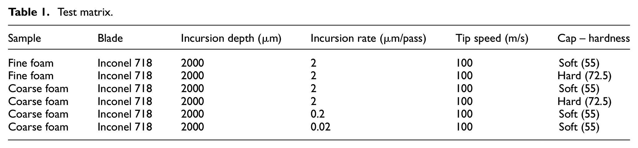
All the abradable samples from this study are tested under the same blade speed of 100 m/s. However, varied incursion rates have been chosen, and are 0.02, 0.2 and 2 μm/pass to cover a range of engine operation conditions, 21 where the maximum value tested is representative of pass-off and the minimum in-flight rub events. 24
An incursion depth of 2000 μm is realistic and representative of rub events commonly seen in aero-engines. 25 Although these tests were conducted at room temperature, and as such the oxidation resistance of the foam could not be fully investigated, it is notable that sufficient heat is generated in the rub during such testing to generate representative wear mechanisms,26,27 and as such the approach is considered appropriate to investigate the test material at this stage of its development. The abradable is sprayed onto the foam to such a level that a continuous layer is formed. This in effect making it equivalent from a sealing perspective to an abradable sprayed onto a metal substrate.
Results
As noted, research around abradable capped foams is necessary to further understand the opportunities that such materials may offer for aero-engine sealing. This study aims to investigate the main factors that directly contribute to the way an abradable capped foam behaves during rub tests. In the results section, wear mechanisms and deformation behaviours will be investigated through the study of three main variables which include sprayed cap hardness, variation in metallic foam pore size and the effects of incursion rate. Firstly the effect of cap hardness is established on a coarse foam, before the role of pore size is explored for both soft and hard capped samples. Finally the influence of incursion rate on a coarse foam with a soft cap is presented.
Effects of cap hardness – Coarse foam
In this section the effect of cap hardness is investigated on the coarse foam. In each case, the incursion rate is 2 μm/pass, blade speed 100 m/s and incursion depth 2000 μm. The two different cap hardness’s referred to as soft and hard, have a hardness difference of 17.25 R15y and are 55 R15y (soft) and 72.5 R15y (hard) respectively.
Figure 5 shows the rub surfaces post-test (a) & (e), with leading blade edge (b) & (f), trailing blade edge (c) & (g) and blade tip (d) & (h). From the two rub surfaces it can be seen that a layer of abradable cap has been retained in both cases. However, in the case of the hard cap (Figure 5(e)), increased fracture and breakage of the surface occurred when compared to the soft cap (Figure 5(a)). Comparing the morphology of the rub surfaces further, it is also clear that compaction and deformation of the cap occurred more readily for the soft cap, given it’s more continuous appearance. Conversely, the harder cap shows abrasion of the cap and reduced bulk deformation, where local fracture also occurs propagating from the edges of the rub track. Whilst edge fracture similarly occurred for the soft cap, it is noticeable that in this case it is less than for the hard cap, but also does not lead to wider cracking of the abradable layer.
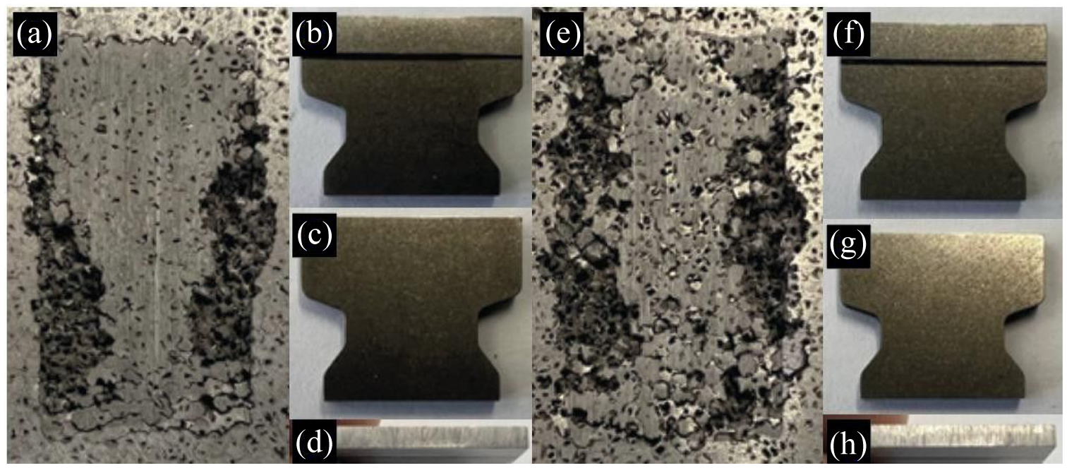
Soft cap: (a) rub surface, (b) leading blade edge, (c) trailing blade edge, (d) blade tip – hard cap, (e) rub surface, (f) leading blade edge, (g) trailing blade edge, and (h) blade tip.
Table 2 shows blade mass measured before and after the rub tests. These measurements were performed in order to determine if either blade wear or adhesive transfer of material from the abradable had occurred, As shown in the table, mass change is negligible for both tests, with a marginal amount of blade wear recorded in each case. These results are consistent with the images of the test blades shown in Figure 5, where Figure 5(d) and (h) for the tips of the blades from the tests with the soft and hard caps respectively, show scratches reflective of light abrasive wear. Whilst the weight loss of the coating would be an appropriate measure for testing of a traditional abradable material metal foams are designed to compact during the rub, this combination makes it very difficult to assess the level of wear from mass difference.
Blade weight change post and prior to rub tests.
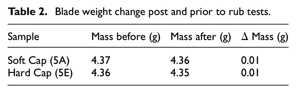
Figure 6(a) and (b) show the forces and blade length change for the soft and hard cap tests respectively, plotted against rub length. Rub length has been previously identified as a suitable plot parameter for abradable linings testing, 21 and represents the total sliding distance of the blade. As shown in the figure, in both cases forces first rise to a peak, before reducing to a steady state level. However, in the case of the softer cap, this peak is higher, with the subsequent steady state value also similarly so. Whilst it may initially be counter intuitive that higher forces are recorded for the softer cap, when coupled with the observed wear scars, this is less surprising. As noted, the soft cap was observed to act as a compliant layer, triggering deformation of the underlying foam. Conversely, the stiffer hard cap was seen to primarily abrade and fracture, with the foam and abradable acting as discrete bodies.
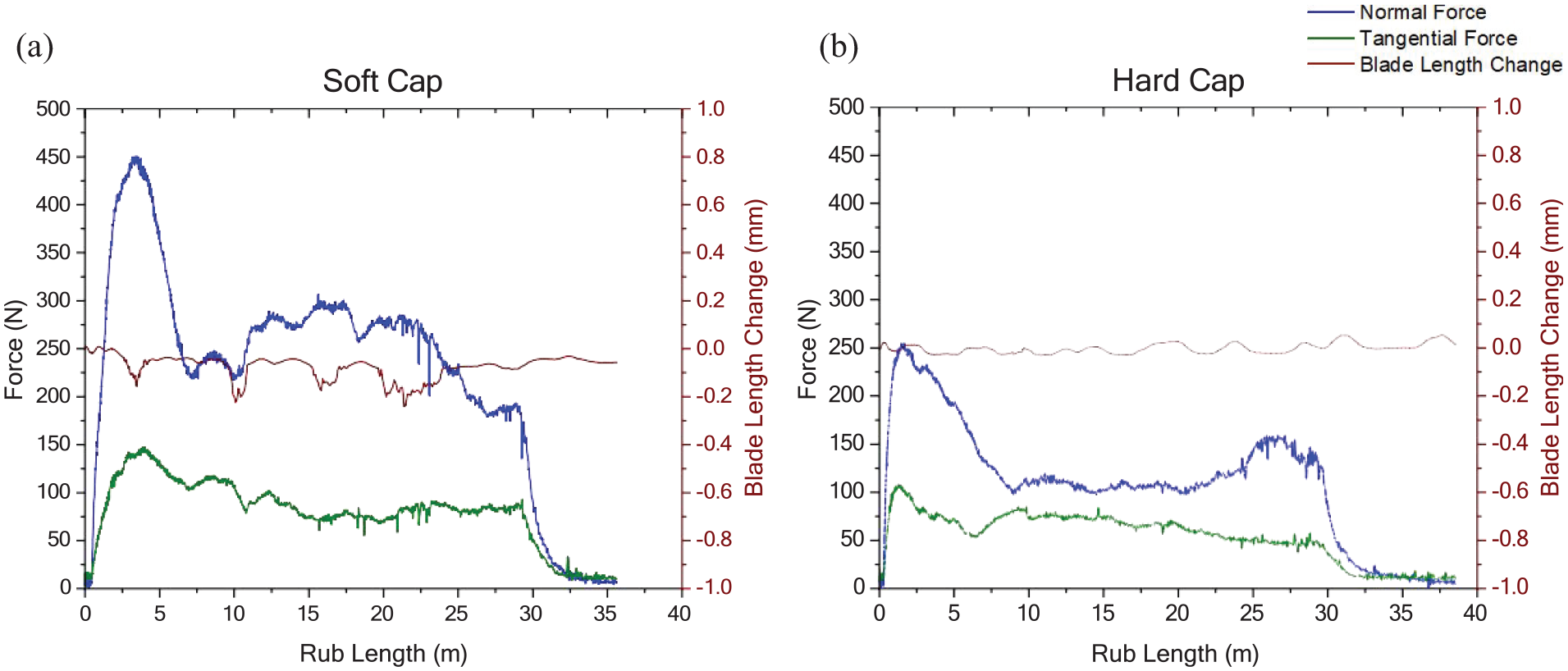
Force traces at fast incursion rates for: (a) soft and (b) hard capped foams.
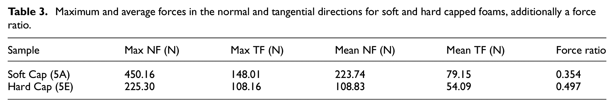
The result seen for the soft cap is also consistent with previous studies investigating the effect of abradable hardness, 28 where soft abradables were observed to rub as opposed to cut and high normal forces develop. This behaviour combined with the compliance of the soft cap itself is therefore likely to lead to the high normal forces and deformation of the cap and foam observed. Whereas, in the case of the hard cap, it’s rigidity and ability to be cut, means that the blade instead removes the abradable, resulting in a lower build-up of normal force. In summary, Table 3 shows the maximum and average normal and tangential forces, along with force ratio, where the previous highlighted differences in normal force and force ratio are evident. In the table, it is also notable that whilst tangential forces for the two tests are similar, the ratio of tangential to normal forces is higher for the hard cap, with an increase in this value linked to a transition to cutting as opposed to rubbing, further supporting the view that the hard cap is cut by the blade.
Maximum and average forces in the normal and tangential directions for soft and hard capped foams, additionally a force ratio.
Finally, considering the observed cracking and increased rupture of the hard capped foam, this is likely linked to the outlined wear mechanic. Whilst as noted forces are lower for the hard cap, it’s high stiffness results in the cap and foam acting as independent bodies, meaning poor energy transfer occurs. In turn, this will result in the energy from the rub that is not relieved via material removal, being concentrated in the near surface, resulting in the observed rupture of the foam ligands. This aspect of the behaviour of the capped foams will be further explored in the subsequent discussion, where material sections will investigate the level of compliance of the foam, alongside any damage.
Effects of pore size – Soft cap & hard cap
As previously noted two foam sizes have been investigated, a fine (1200 μm) and coarser (2000 μm) foam. In this section, results are presented for both foam types, with either a hard or soft cap, once again at a high incursion rate condition of 2 microns per pass.
Figure 7 shows the results for the two foam sizes for the soft cap. In the figure, the previously detailed result for the coarse foam with the soft cap is shown, alongside that for the fine foam with a similar soft cap. At this point it should be noted that mass loss measurements were similarly made for the blade samples both pre and post test, with negligible changes once again observed, combined with light abrasion marks similarly on the blade tips. As shown in the figure, where previously for the coarse foam the cap to a large degree remained at the end of the test, with deformation observed in the underlying foam, in the case of the fine foam, the cap has been removed. Further investigation determined that the cap delaminated from the foam surface, and this will be further investigated via the force measurements recorded (Figure 8).
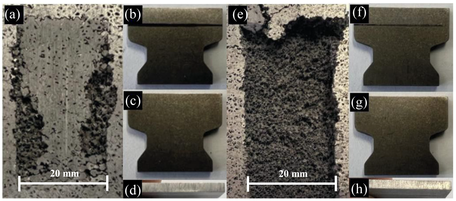
Coarse foam: (a) rub surface, (b) leading blade edge, (c) trailing blade edge, (d) blade tip – fine foam, (e) rub surface, (f) leading blade edge, (g) trailing blade edge and (h) blade tip.
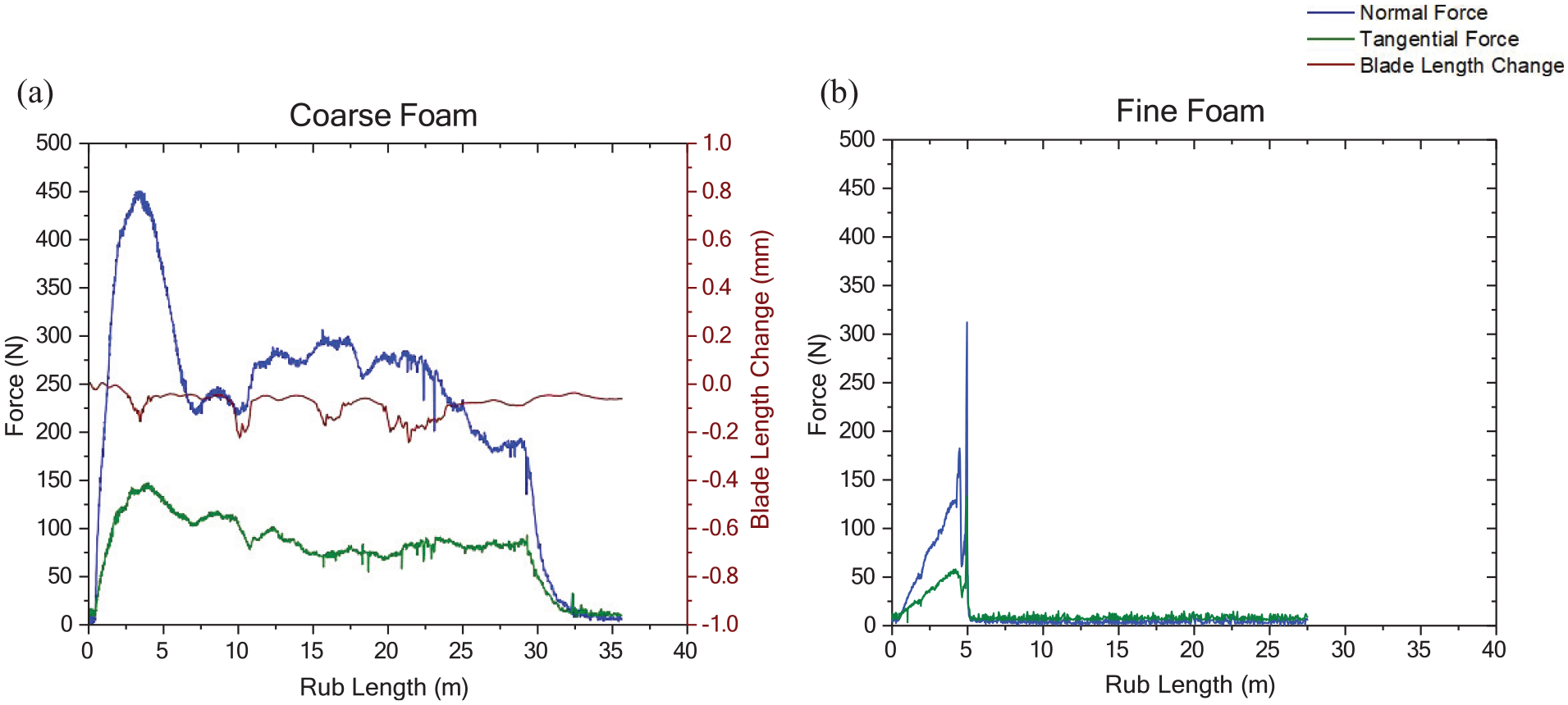
Force traces for soft cap where: (a) coarse foam and (b) fine foam.
As shown in the figure, whilst in the case of the coarse foam forces first peaked before plateauing to a steady state, for the fine foam failure occurred in the initial stages of the test as the forces began to rise. This result is consistent with a previous study, where it has been seen that smaller pore sizes result in localised stress and strain accumulation within the upper layers of the foam, 6 with this providing an explanation as to why delamination has occurred at the foam – cap interface. Considering this result in the context of that previously seen for the coarse foam with the hard cap, it is likely that the increased stiffness of the fine foam, has similarly led to the foam and cap behaving as independent bodies, resulting in a similar although more extreme failure.
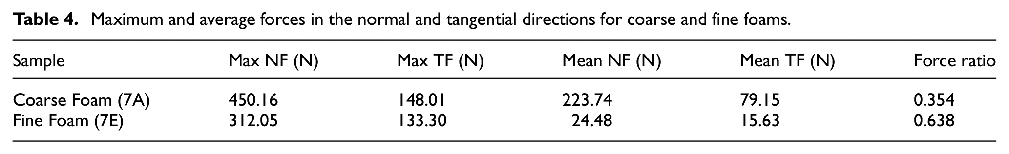
Maximum and average forces for the tests, alongside force ratios are shown in Table 4, where it is noticeable that failure of the fine foam occurred at a lower normal force than the coarse foam sustained, further highlighting the likely role of stress concentrations in the failure observed. It is also notable that whilst stiffer overall, the individual ligands of the fine foam are weaker when compared to the coarse foam, meaning they are also more susceptible to failure in such cases.
Maximum and average forces in the normal and tangential directions for coarse and fine foams.
Finally, moving to the test performed with the fine foam with the hard cap, almost immediate failure was recorded. Considering the previous result for the coarse foam with the hard cap (Figure 5(e)), where the stiffness of the cap was identified as leading to the cap and foam acting as discrete bodies, combined with a similar effect identified for the fine foam with the soft cap (Figure 7(e)), it is unsurprising that was the case. Clearly, the combination of the hard cap with the fine foam accentuates the identified issue, leading to the almost instantaneous rupture observed at the foam – cap interface.
Effects of incursion rate – Soft cap & coarse foam
The final tests in this study compare the effect of incursion rate for the coarse foam with the soft cap. In addition for the previously presented result for this material at an incursion rate of 2 microns per pass in Section 3.1, results are now presented at 0.2 and 0.02 μm/pass. This material combination was chosen to explore the influence of incursion rate, as it represented the most promising foam-abradable system.
Figure 9 shows a comparison of the rub surfaces and blades at different incursion rates. As previously detailed, at 2 μm/pass (Figure 9(a)) deformation of the cap/foam system occurred. Moving to incursion rates of 0.2 and 0.02 μm/pass (Figure 9(a) and (i) respectively), significant differences can be seen in the rub surfaces, with removal of the cap having occurred. As might be expected, little to no wear of the blades has occurred as a consequence of the cap detachment, with this result confirmed via mass change measurements. The force measurements for these two tests are plotted against rub length in Figure 10, and as shown in the figure, forces are low throughout the test, although it is unclear at what point detachment occurred.
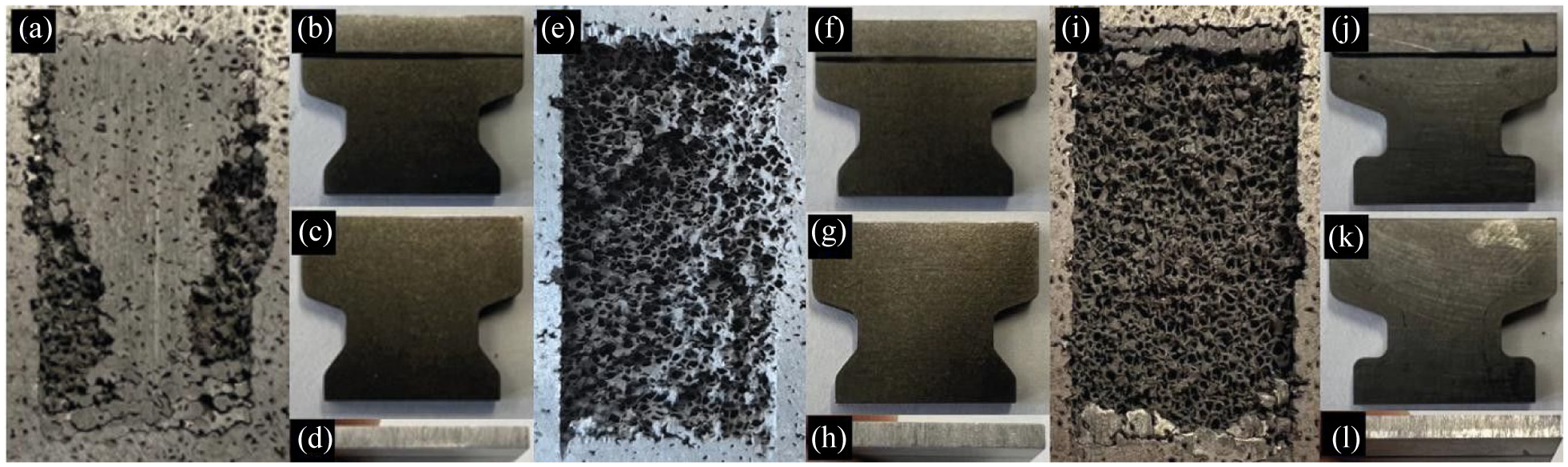
2 μm/pass: (a) rub surface, (b) leading blade edge, (c) trailing blade edge, (d) blade tip 0.2 μm/pass, (e) rub surface, (f) leading blade edge, (g) trailing blade edge, (h) blade tip – 0.02 μm/pass, (i) rub surface, (j) leading blade edge, (k) trailing blade edge and (l) blade tip.
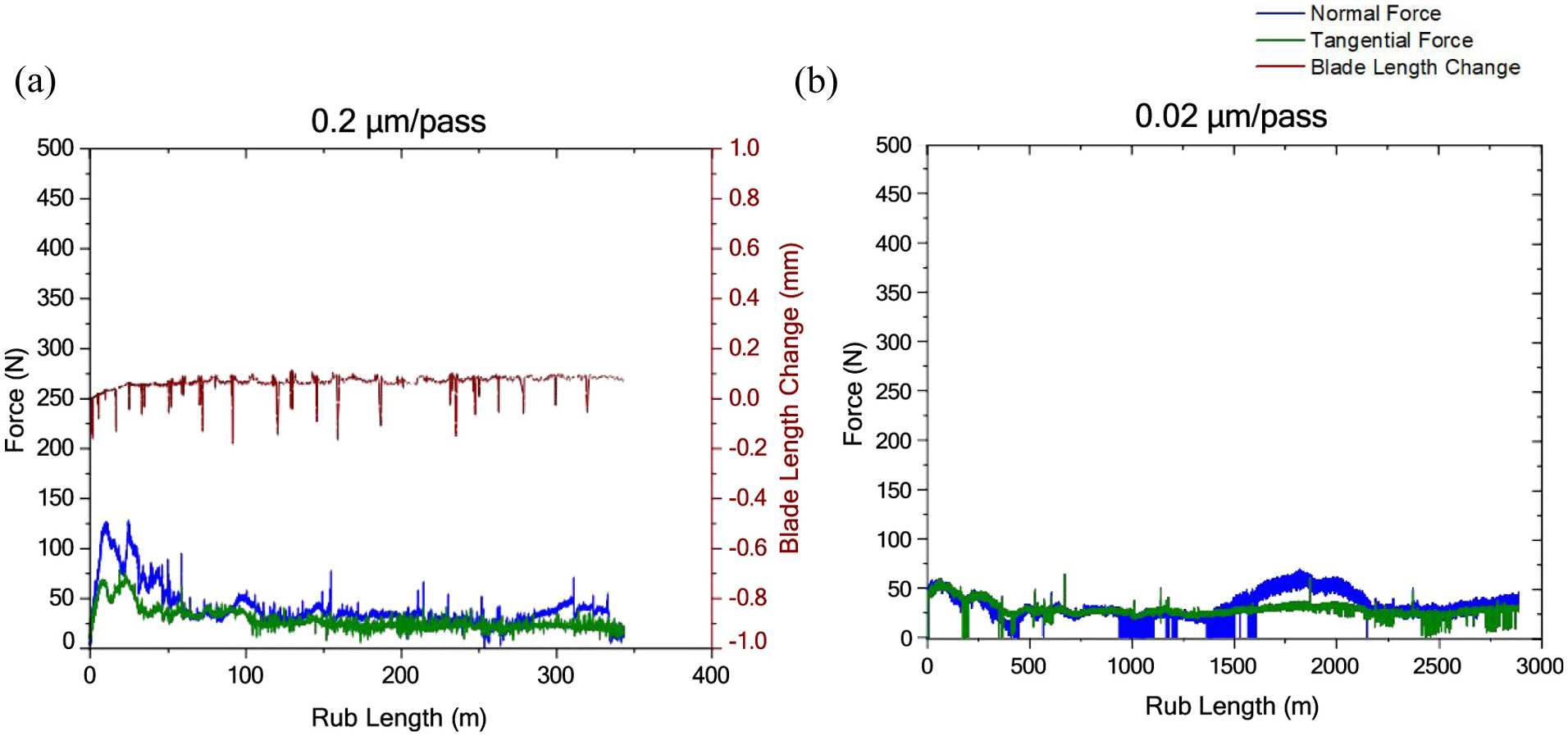
Force traces for soft cap where: (a) 0.2 μm/pass and (b) 0.02 μm/pass.
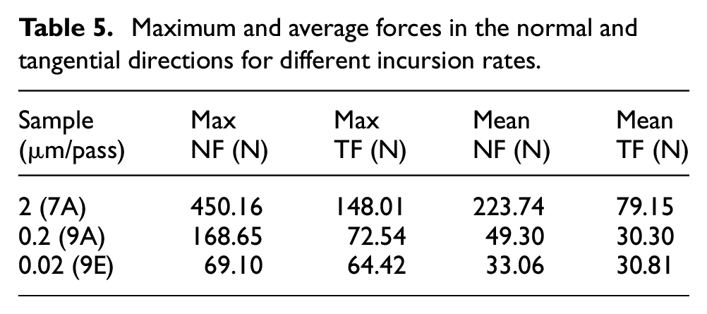
In order to compare forces across the three incursion rates investigated, average and maximum forces are once again detailed, and are shown in Table 5. In this case, force ratio has been omitted given the low values of force recorded at the lower two incursion rates leading to significant variability in the data, albeit with this indicative of an intermittent rubbing contact. As shown in the table, forces recorded at incursion rates of 0.2 and 0.02 μm/pass are significantly lower than those seen at 2 μm/pass, with this providing an explanation for the behaviour observed. Previous work has shown that at faster incursion rates, energy input into the system per strike of the blade is higher, 6 and although for these tests a soft compliant cap has been used, a given amount of energy will still be required to actuate the cap and trigger deformation of the cap / foam system. Given the low values of force recorded for the latter incursion rates, it is likely that this threshold was not reached and energy was once again concentrated at the cap/foam interface, leading to the observed failure. However, from the data it is unclear as to whether initial cutting of the cap occurred or a more instantaneous failure, and this will be further explored in the next section.
Maximum and average forces in the normal and tangential directions for different incursion rates.
Discussion
In order to further investigate the wear mechanisms present, samples were vacuum impregnated, mounted and sectioned. This approach was undertaken in order to determine to what degree the abradable cap was preserved post-test, as well as to investigate collapse of the foam and in turn accommodation of the rub. In addition images recorded using the high speed camera were also analysed to further investigate the progression of the material removal mechanism, with images presented at incursion depths of 500, 1000, 1500 and 2000 μm. In combination, the further analyses detailed are used to further discuss the influence of cap hardness, foam pore size, and incursion rate.
Soft versus hard caps
As previously highlighted, for the soft cap with the coarse foam, progressive collapse of the underlying foam was identified, where forces first peaked before plateauing to a steady stage value. As shown in Figure 11, when viewed in combination with the force data, images taken from the high speed camera support this view, where gradual collapse of the rub track is evident. From these images, it can also be determined that rupture of the abradable cap only occurs at the edges towards the end of the rub event, with this likely linked to edge tearing as the cap is further pressed into the foam.
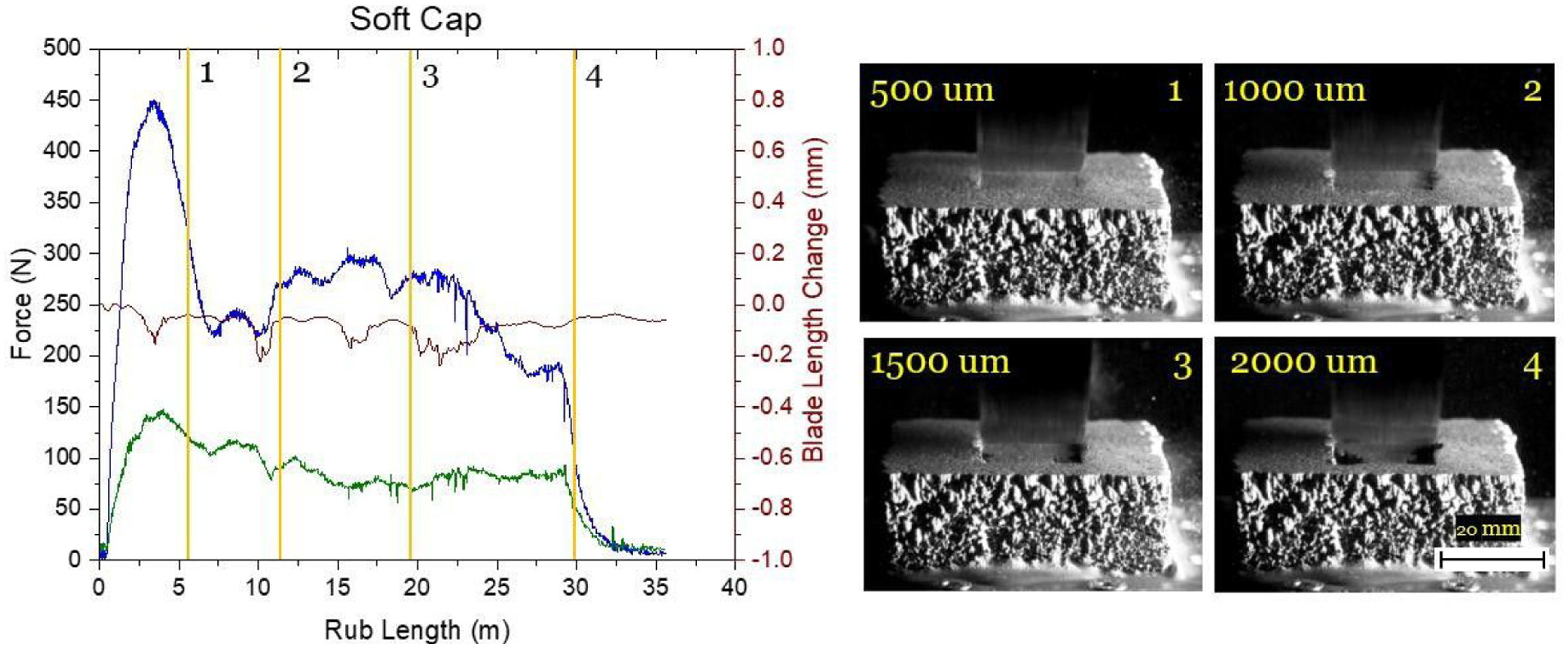
Rub progression stages at different set incursion depths for a soft-capped coarse foam abradable.
These observations are supported by the material sections shown in Figure 12, where a broadly uniform cap of abradable material (1.2 mm) is preserved along the centre line of the rub in the direction of blade travel, with this accompanied by collapse of the underlying foam structure. Conversely, at the edges of the rub track, tearing is evident, with both abradable cap and the underlying foam structure removed.
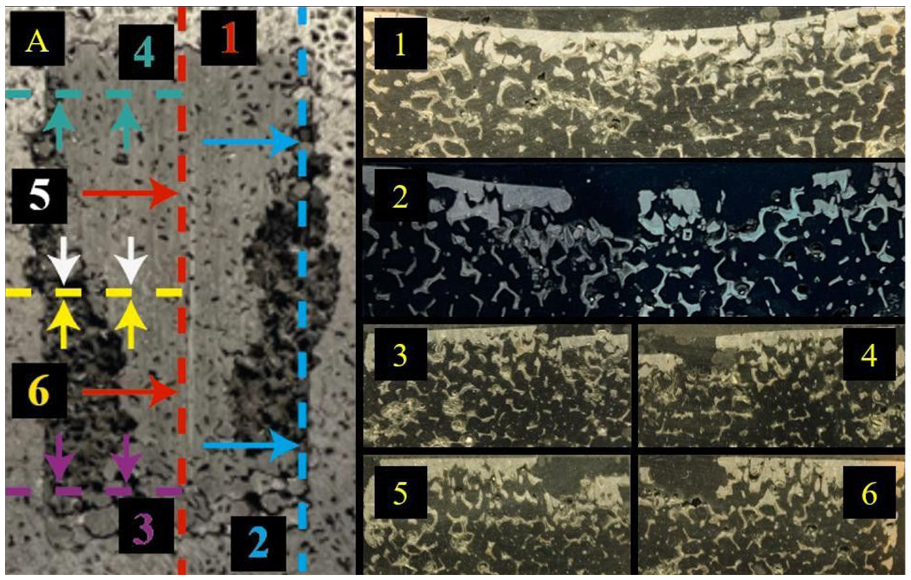
Soft capped coarse foam abradable showing sections in different planes.
Moving to the test with the hard cap and coarse foam (Figure 13), significant differences can be observed. As previously noted, forces were at a lower level, with this determined to be due to cutting of the abradable cap. As shown in Figure 13, a pronounced rub track is visible on the sample from as early as 500 microns into the rub depth, where this was more limited in the case of the soft cap at the same stage. This highlights the differing wear mechanic present for the two samples, where in the case of the soft cap material is compressed, until ultimately the foam deforms, where for the hard cap it is removed via cutting.
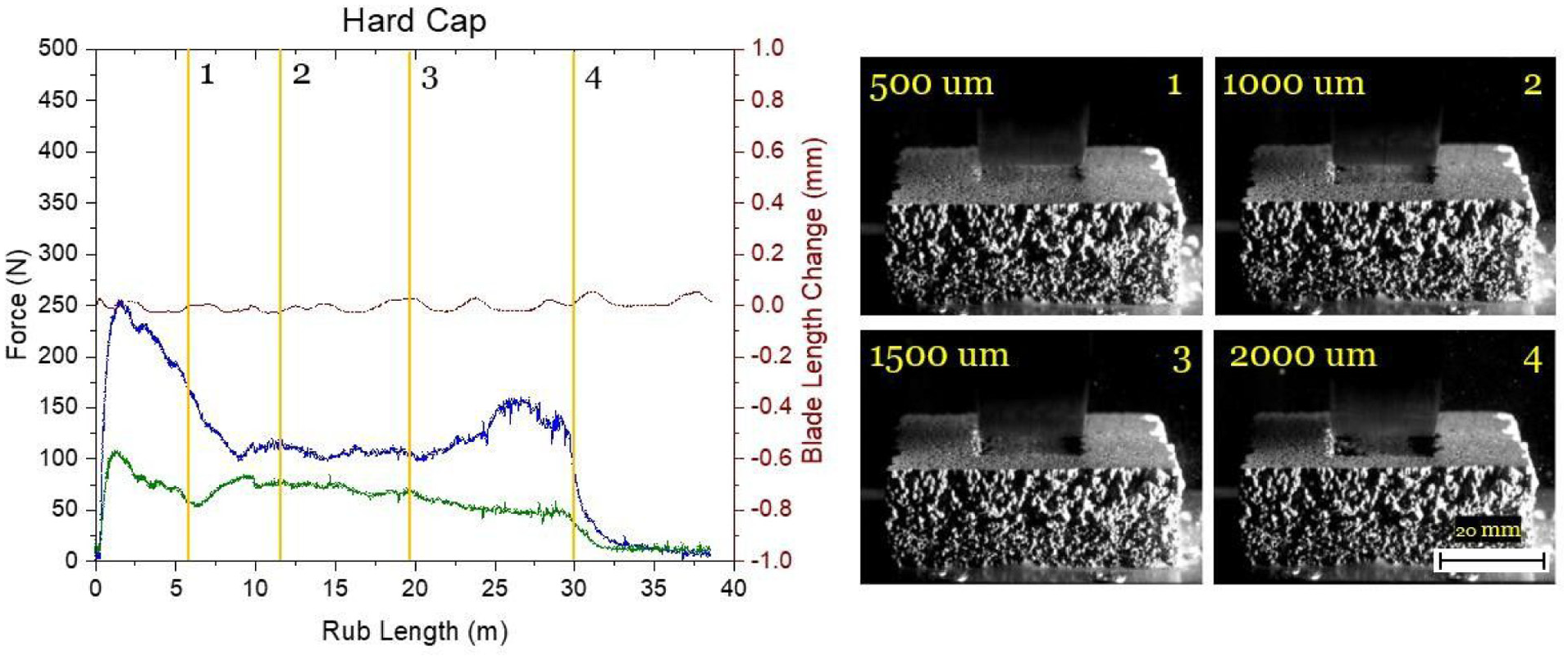
Rub progression stages at different set incursion depths for a hard-capped coarse foam abradable.
This view is further supported by the section taken through the hard capped foam. As shown in Figure 14, where it can be seen along the centre line of the rub track in the direction of blade travel, that the cap is thinned (0.3 mm), with little to no compaction of the underlying foam. At the same time, as was the case for the soft capped foam, tearing has similarly occurred at the edges. Whilst this latter observation doesn’t imply large scale compaction of the foam has taken place, and oppose the result observed for the centre line, it does suggest more generally that a small level of deformation may be taking place, as if the abradable was being completely cut, such tearing would not take place.
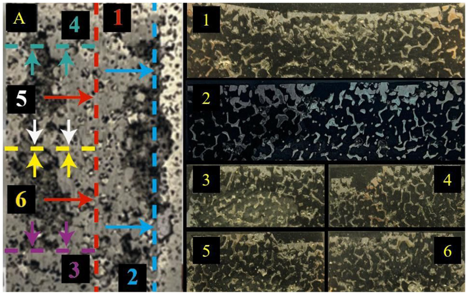
Hard capped coarse foam abradable showing sections in different planes.
As previously noted, there are differences in the amount of cutting visible after sectioning of the abradable samples post-test. Converting the images to greyscale, and then segmenting them into metallic & porous phases. The amount of cutting that has taken place can be inferred from the remaining metallic material in the near surface, given the cap is significantly more dense than the foam. In turn, a numeric assessment can be made as to whether more cutting has indeed taken place for the hard cap.
Following the analysis detailed in Figure 15, the determined metal percentage in frame for both the hard and soft caps is 33.5% and 43.5% respectively. Whilst there will be some discrepancies due to the metal ligand phase having varied percentage quantities dependant on the section taken, this has been minimised by capturing as little metallic foam. Even taking into account such discrepancies, the outcome still remains evident that for the soft cap an additional 10% material has been retained. Reflective of the compaction taking place. In the case of the hard cap, the material loss determined can be associated with an increase in cutting.
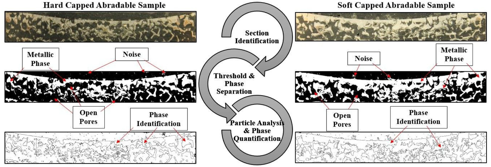
Analysis steps for quantification of metallic phase remains over the same section area, including threshold and porosity percentage.
Energy transfer and compaction
As highlighted in the results section, the variables of cap hardness, pore size and incursion rate are broadly linked in terms of the wear mechanism generated, and the response of the abradable capped foam to the incursion event. In the case of a hard cap, the abradable and foam act as discrete elements, with material being removed by the blade from the top surface of the abradable, whilst at the same time some energy from the interaction is transferred to the underlying material. This latter energy transfer and compression of the system is in particular evidenced by the edge tearing seen for these samples. However, given the lack of compliance of the hard cap, and in turn inability to actuate the foam, energy is stored in the near surface and rupture occurs. In many respects this is similar to the wear mechanic seen for nickel based abradable materials at moderate and high incursion rates, 29 where material removal fails to keep pace with the incursion rate and compression followed by surface rupture of the sample occurs.
In a similar way, when the foam is stiff, regardless of the compliance of the abradable cap, a related wear mechanism occurs. For this case, the foam and abradable again act as single bodies, with energy once more being stored in the near surface, should the rub not be accommodated by removal of the abradable by the blade. This in turn leads to ligand failure, and fracture of the abradable cap.
Finally, as seen in the case of the coarse foam with the soft cap at reducing incursion rate, failure once gain occurs. Given that the reducing incursion rate is accompanied by reduction in normal force, 3 this creates a situation where the energy input is not sufficient to globally deform the foam and in many respects is similar to the situation where the cap is either too hard or foam too stiff. Different stages of rub progression shown in Figure 16 clearly highlight the localised failure of the cap where no global deformation occurs. It should be noted that an FE model can be used to further describe and explain the energy transfer dynamics however due to the spontaneous failure of the rub this should be revisited once a more controlled rub is achieved even for the lower incursion rates.
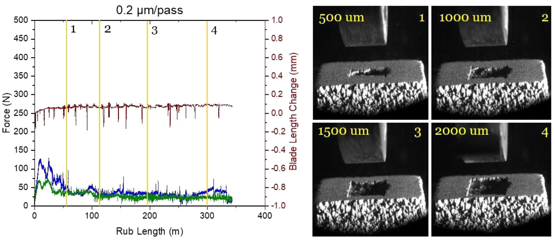
Rub progression stages at different set incursion depths for a soft-capped coarse foam abradable for a lower incursion rate.
The energy transfer dynamics can to a degree be explained by a previous study on the impact response of sandwich structures, 30 where large differences in young’s modulus were present between the outer skin and core. In this case, the surface film had a significantly higher young’s modulus in comparison to the underlying layers, and it was shown under point loading that energy is transferred through the top surface layer leading to crumbling of the underlying materials due to the large modulus delta.
Considering the result for the fine foam, the modulus of the Metco 320 surface coating is 17.22 GPa 23 and metallic foam 0.09 GPa. 29 Much like in the case of the study highlighted, energy appears to be transferred through the cap, and the underlying foam crumbles in the near subsurface leading to large amounts of material removal. As noted, the situation is also similar in other cases in this study. That said, it is notable that this does explain the result seen for the coarse foam with a soft cap at high incursion rate, where despite a significant difference in modulus, collapse is observed. These inter relationships are highlighted in Figure 17, where as shown the only sample to achieve continual energy transfer and deformation of the foam and cap, was the coarse foam sprayed with the soft abradable. On this point, it is interesting to note that in this case the soft abradable was both advantageous given the fact it had a lower elastic limit, 23 and also in that it didn’t readily cut, meaning normal forces were high. 6 In particular this latter point is opposed to conventional research into abradable materials, where a failure to dislocate, can lead to high forces and temperatures and in turn blade wear. However, in this case, given the need to actuate the foam sample it was of benefit. In this case, it also appears that despite the difference in modulus still being high, that the compliance of the cap combined with the low failure strength of the foam, leads to a different and more local energy transfer.
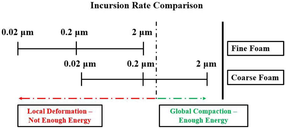
Links between incursion rate and pore size for mechanism activation.
Conclusion
A series of tests have been performed investigating the rub response of abradable capped metal foams, with the aim of creating a hybrid material that is able to collapse and conform to the blade incursion event. It was identified that the compliance of the cap along with the stiffness of the foam were key variables, where if either the abradable cap was too hard or the foam too stiff, deformation of the underlying foam did not occur and instead sample failure took place. Similarly, whilst good results were achieved in the case of a soft cap on a coarse foam, deformation of the hybrid material was reliant on sufficient actuation through a high incursion rate, as the incursion rate was linked to the force input to the system. In cases where the incursion rate was reduced, failure to deform the material and accommodate the incursion once again occurred, with a failure similar to that seen for hard abradable caps or stiff foams. Whilst sealing metrics are of great importance and should be considered for any sealing materials, the failure of the cap and foam combination to perform at the lower incursion rates is still an ongoing issue. Finally, whilst considered detrimental to abradability in more conventional settings, soft abradables were found to be of benefit in this study, as the rubbing as opposed to cutting present promoted higher normal forces, leading to the desired deformation of the foam material. Edge tearing was also identified as an issue due to the discontinuity at the extremities of the rub track, and alleviating this represents a topic of further work.
Footnotes
Declaration of conflicting interests
The authors declared no potential conflicts of interest with respect to the research, authorship, and/or publication of this article.
Funding
The authors received no financial support for the research, authorship, and/or publication of this article.