
Abstract
The dual-ported shroud casing has two ports over the impeller section in a centrifugal compressor, different from the traditional ported shroud casing. This paper uses numerical simulations and experiments to investigate the effects of the dual-ported shroud on the centrifugal compressor, including aerodynamic performance and aeroacoustics. According to the experimentally measured compressor performance map, the novel finding is that the dual-port casing treatment extends the compressor operating range by improving the instability margin and increasing the compressor choke flow capacity. The mechanism contributing to the choke flow capacity increase is the bypass function. The dual-ported shroud casing bypasses a part of the air to enter the impeller channels at the blade tips without going through the impeller geometry throat. Besides the benefits, the efficiency and aero-acoustic measurements identify the disadvantages of the dual-ports casing treatment: the peak efficiency deterioration at high rotational speeds and louder noise emission at the compressor inlet.
Introduction
Turbochargers were developed one hundred years ago 1 and have become a well-known device in the internal combustion (IC) engine field. With the trend of downsizing IC engine, the turbocharger has become a necessary device due to its advantages, such as the increased fuel economy, improved low-end torque, increased exhaust gas recirculation driving capacity, and increased power density. 2 With a turbocharger, however, the power system design often has challenges in the stable operating range of its compressor, 3 such as the compressor surge caused by the tip-out or back-out operation. Improving the operational margin has been challenging for a turbocharger compressor design due to surge at the low end and the limitation of flow capacity under high flow conditions. Therefore, a wide operating range is one of the requirements for the turbocharger compressor design in the turbocharged IC engine industry.
Self-recirculation casing treatment, or ported shroud casing, was first proposed in 1988 by Fisher 4 to extend the operating range of compressors by either improving the surge margin or increasing the flow capacity. Since then, the self-recirculation casing treatment has been widely used in turbochargers of IC engines and other applications where compressors with a wide flow range are required. 5 Regarding the surge margin extension, the casing treatment allows a portion of the flow to recirculate back to the inlet duct from the impeller tips. 6 For the choke flow boundary extension, the ported shroud allows the partial flow to enter the impeller. 7 In most applications, a single port on the surface of the shroud cover in the impeller section makes it hard to achieve the surge margin improvement and the choke flow rate increase because the surge limit extension and flow capacity improvement require different port locations and geometry designs.
Plenty of investigations have been conducted to understand the effects of the casing treatment on the aerodynamic performances8,9 and acoustics characteristics 10 of a compressor. With the self-recirculation casing treatment, the compressor aerodynamic performance deteriorates at the design point and rises at the off-design points. 11 The casing treatment is also attributed to extra/additional noise emission. 12 In a centrifugal compressor with casing treatment, the recirculating slot inside the shroud casing is a channel through which the strong pressure disturbance induced by the impeller propagates to the upstream region, even emitting to the field in the duct inlet. Consequently, the casing treatment tends to raise the compressor noise level at a few operating points, which limits the casing treatment application in the spark-ignition engines.5,13
Given that one port on the shroud casing cannot match well with the pressure gradient change on the shroud casing surface, Sun et al. 2 first proposed the novel concept of dual-port shroud casing. Subsequently, the idea has been further developed.14–17 Unlike the traditional single-port casing treatment, the dual-port casing treatment provides one more port for air flows and noise propagation. Following our previous research, 15 a centrifugal compressor with dual-port casing treatment was redesigned, and then aerodynamic and acoustic measurements were conducted. Based on the experimental results, this paper analyzes and summarizes the advantages and disadvantages of the dual-port casing treatment regarding the aerodynamic performance and aero-acoustic characteristics and reports the related mechanisms.
Compressor prototype
Compressor geometry
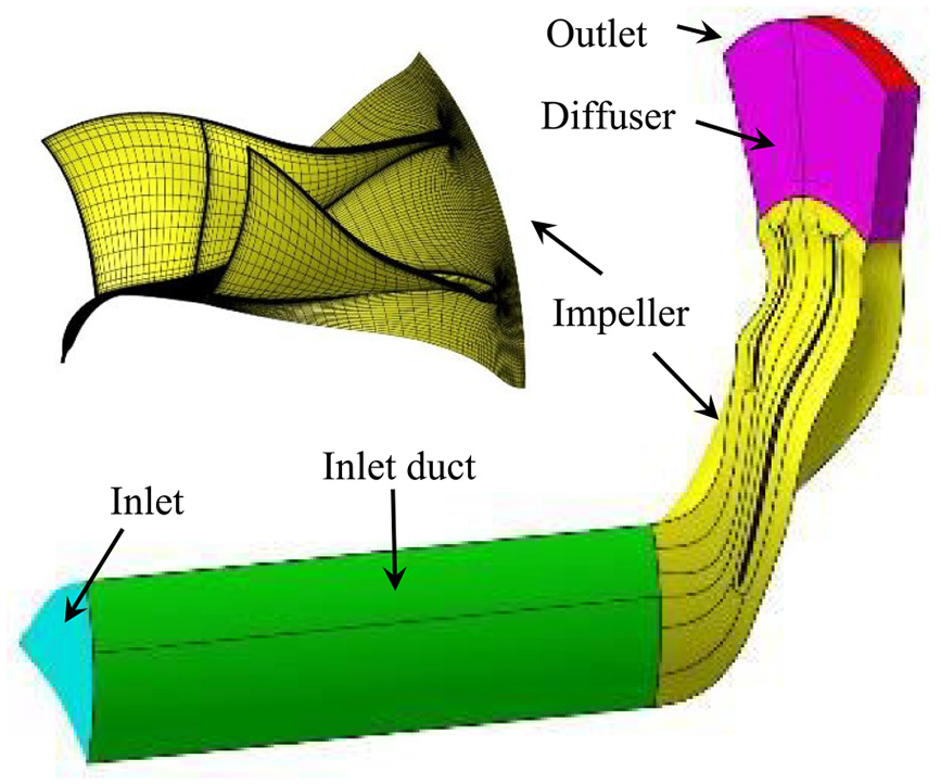
The research object is a centrifugal compressor, as shown in Figure 1(a). It consists of an inlet duct, an impeller, a vaneless diffuser, a volute, and an exit pipe. As shown in Figure 1(b), the impeller wheel consists of 12 blades, including 6 main blades and 6 splitter blades. Table 1 lists the detailed geometry parameters of the compressor model. A five-axis milling machine tool was employed to produce the impeller because of its high efficiency and low cost. As shown in Figure 1(b), a few milling cutter traces are left on the surface of the impeller hub surface, changing the roughness. The impeller remains the same in the experiments to remove the roughness’s effects.
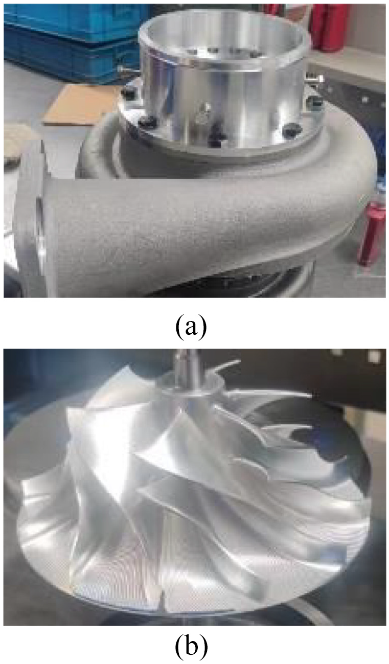
Photos of the centrifugal compressor: (a) compressor prototype and (b) impeller photo.
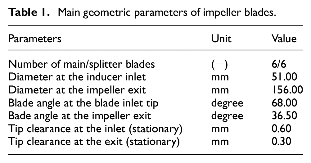
Main geometric parameters of impeller blades.
Ported shroud casing
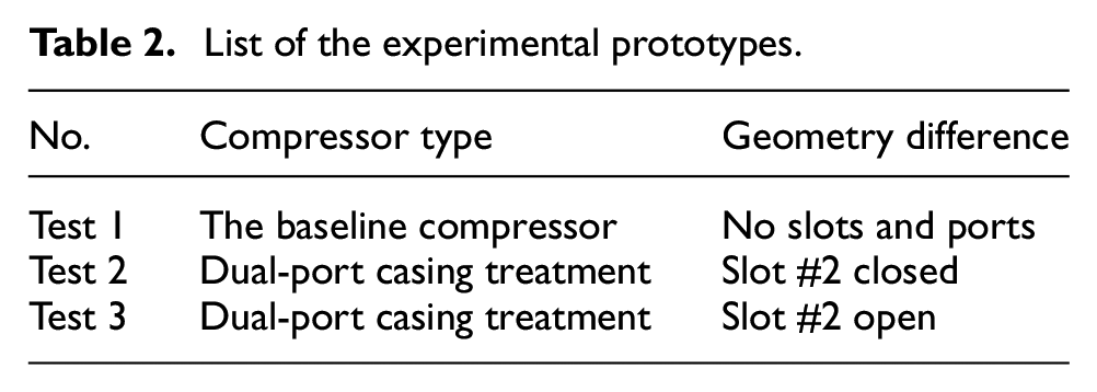
Two kinds of shroud casing are involved in this paper, the shroud casing with and without ports, as shown in Figure 2. The ported shroud casing has two ports over the impeller section, called the dual-port shroud casing in this paper, and its structure is illustrated in Figure 2(b). During experiments, the valve in slot #2 was manually controlled. All prototypes tested in experiments are listed in Table 2.
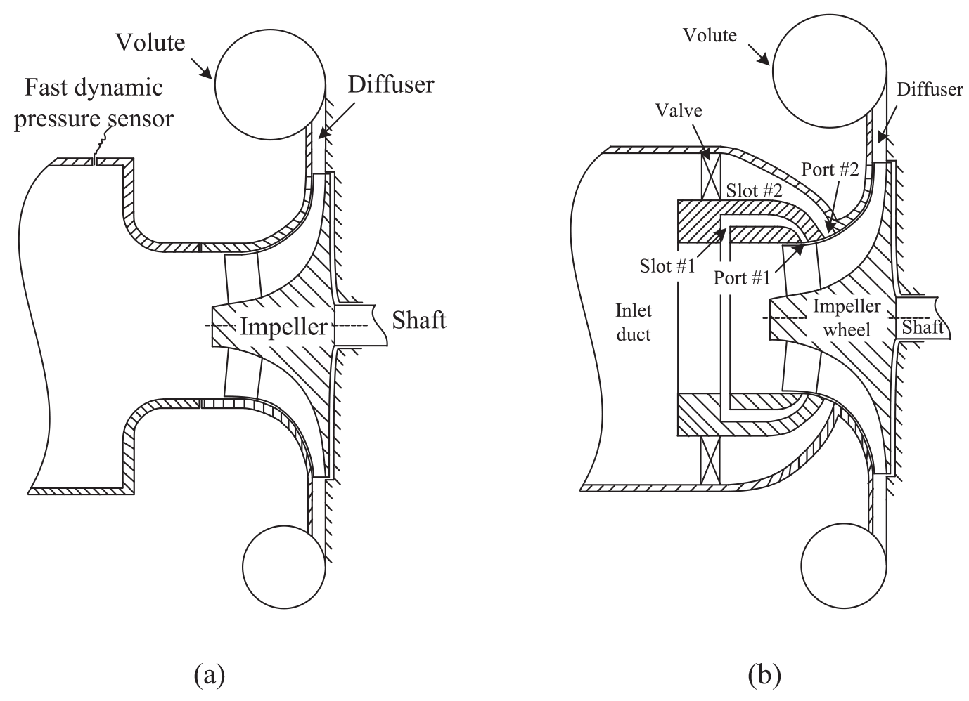
Illustration of the dual-port compressor: (a) baseline compressor and (b) compressor with dual-ported shroud casing.
List of the experimental prototypes.
Port #1 is positioned upstream of the splitter blade’s leading edge (LE) according to the pressure distribution. The connection of port #1 and slot #1 can take advantage of the pressure difference to form a self-circulating casing treatment with low total pressure loss. The self-circulating flow has the same principle as the traditional ported shroud technology and aims to improve the compressor surge margin.
Another slot is designed to connect port #2 with the inlet duct, named slot #2 in the following sections. Under the positive pressure difference from the inlet duct to the blade tips, the air can enter the impeller tips from the inlet duct through slot #2. Consequentially, it is also the self-circulating casing treatment.
Unlike the traditional ported shroud casing treatment, there is an active control valve in slot #2. The valve can switch slot #2 according to the compressor operating point. For instance, when the compressor operates near the choke point, the valve is spun to open slot #2 while it is positioned to close slot #2 as the compressor operating point is near the surge boundary. For more details about the structure of the compressor, please refer to Figure A1 given in Appendix A. The geometric design of the valve located in slot #2 is out of the scope of this paper, so it is not introduced in detail.
Numerical simulation
The numerical model of the compressor impeller was built with the NUMECA Fine/turbo software package (Version 11.1). The numerical model aims to simulate the flows in the centrifugal impeller, thus revealing the pressure distribution.
Computational mesh
In the numerical model, the tip clearances were included in the computational domain. The narrow gap between the rear part of the impeller and the back plate was neglected. An auto-mesh generator was employed to build the computational mesh with the O4H mesh topology structure, an O-type block surrounded by four H-type blocks. As shown in Figure 3, the grids consisted of structured meshes with hexahedral cells, multi-level cells, and multiple block technologies. 18 Mesh points near walls were controlled by a clustering technology, which generates more grid points near the wall to simulate the flow inside the boundary layer accurately.
The computational domain and impeller mesh.
There are about 1.44 million grid points for the mesh of one flow passage. With the periodic boundary conditions, the single-passage mesh can significantly lower the CPU time and memory requirement. Another reason is that meshing a single passage can meet the research requirement. The average y+ value is 4.06, and the maximum is 10, within the range the turbulence model requests. Before the current numerical simulations, a group of computational meshes with the same topology but different grid points in every direction were calculated. The numerical results proved that the mesh satisfied the essential requirements for simulating the flow field of the compressor. The sensitivity analysis of the grid size can be seen in the Appendix.
Numerical scheme
The Reynolds Averaged Navier-Stokes (RANS) equations were solved with the Spalart-Allmaras (S-A) turbulence model. The S-A turbulent model features high efficiency and robustness 19 and, according to the comparison in Reference Yang et al., 19 is suited to simulate a compressor of this sort. The discretization in space was based on a cell-centered control volume approach. The viscous fluxes were determined in a purely central way, and the gradients were calculated directly on cell faces. The inviscid fluxes were upwind-based numerical fluxes and the central schemes. An explicit four-stage Runge-Kutta scheme was used. The local stepping was chosen due to the increased convergence rate. Besides, the solver used multigrid and residual smoothing technologies for efficiency and fast convergence.
Boundary condition
Total pressure and total temperature were specified at the inlet boundary with a fixed velocity orientation paralleled with the straight inlet pipe. Their distribution was assumed to be uniform. The viscosity required by the Spalart-Allmaras turbulent model for turbulent properties was specified at the inlet condition. Because only one impeller channel was meshed, the periodical boundary was used. By using an adiabatic assumption, the heat transfer at all walls with the surroundings was neglected.
Moreover, the velocity vector vanished on the walls, the so-called non-slip boundary condition. At the outlet boundary, the static pressure was specified. The remaining dependent variables on the outlet boundary were obtained from the interior field through the zero-order extrapolation.
Experimental setup
Test rig
Experiments were conducted using a turbocharger flow bench testing rig at the Kangyue Technology Company. The test rig is depicted in Figure 4, which is constructed in a semi-anechoic chamber in which all walls have been silencing treated.
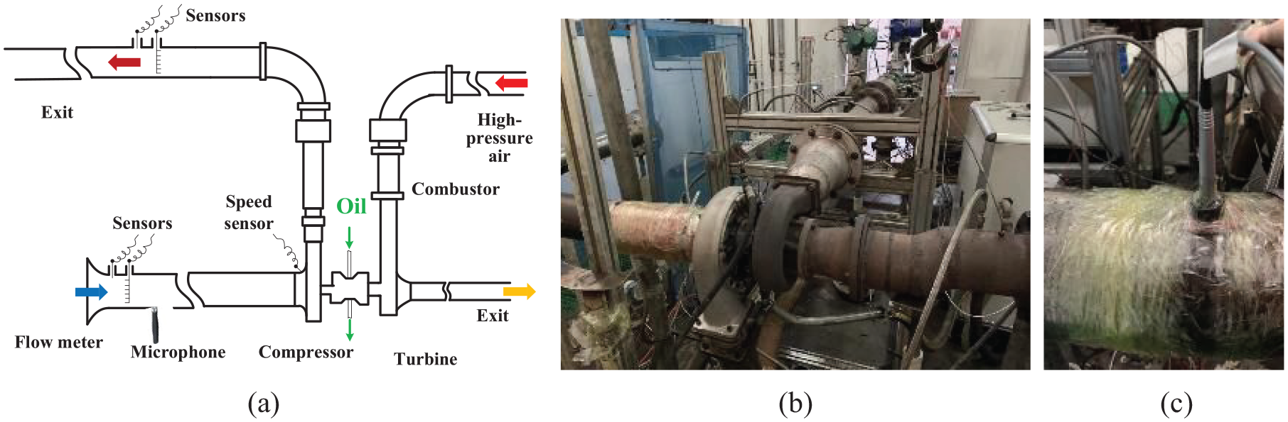
Setup of the experimental rig: (a) sketch of the experimental setup, (b) schematic of the test rig, and (c) pressure microphone on the compressor inlet duct.
A radial turbine actuates the compressor. The turbine wheel is fixed to one shaft end, and the tested impeller is set to the other. The shaft transfers the torque and power from the turbine to the compressor.
The combination of the high-pressure airflow at the turbine inlet, the fuel mass flow rate of a combustor, and the opening of the throttling valve at the compressor exit pipe controls the compressor operating point. By reducing the throttle valve opening, the operational condition of the compressor can be adjusted from the choke point to the surge occurrence at a compressor rotational speed. The measurement was repeated at other speeds to obtain more experimental data. The compressor speed is monitored by mounting an eddy current sensor in the shroud casing. The stability boundary is the last operating point before the surge occurrence. The present experiments tested four impeller exit speeds ranging from 245 to 460 m/s. The velocity is calculated according to the shaft rotational speed and the impeller’s diameter. The relative Mach number is below 1 at the impeller exit.
The heat transferred from the turbine side to the compressor would raise the air temperature at the compressor exit, affecting the compressor efficiency accuracy, for the compressor efficiency is calculated according to the air temperatures acquired at the compressor inlet and outlet. For that consideration, the oil pressure is further raised to take away more heat from the bearing system, reducing the heat transfer to the compressor. In addition, the same measurements were conducted on different days, and the compressor isentropic efficiency acquired from each measurement showed good agreement, validating the good repeatability of this experiment despite still heat transfer effects.
Measurement
The total temperature, total pressure, static temperature, static pressure, mass flow rate, and acoustic signal are measured in the compressor inlet duct. The pressure was acquired by the pressure sensor, which had a measurement accuracy of 0.1%. The mass flow rate was measured using a double folium flow meter at the upstream end of the compressor inlet duct. The flow meter has an accuracy of 1.5%.
The acoustic characteristics were captured using a 1/2-inch Brül & Kjær type 4192 pressure-field microphone mounted at the inlet duct, as shown in Figure 4(c), about 10 times the duct diameter away from the inducer inlet. The acoustic signal was acquired at a sampling rate of 100 kHz for 10 s. A similar microphone by setup was used and reported by Sharma et al. 20 and the effectiveness of that was proved by them.
At the compressor exit pipe, the total temperature and pressure were measured and used to calculate the compressor pressure and temperature ratios. The compressor isentropic efficiency can be calculated with the pressure and temperature ratios.
Results and discussion
Aerodynamic performance
Figure 5 compares the aerodynamic performance maps of the compressor with and without the dual-ported shroud casing. The mass flow rate was normalized by dividing the chocking flow rate of the compressor without casing treatment at the speed of 460 m/s. Figure 5(a) shows improved compressor pressure ratios around two ends of the two top speed lines, as depicted with the blue and pink curves (the results of Test 1 and Test 2). With the improvement of the pressure ratio (the total-to-total pressure ratio), the map’s width is also increased at the two ends at high rotational speeds. That is, the instability margin and the chocking flow capacity are improved. The improvements at two ends of a high-speed line are the technical advantage of the dual-ported shroud casing. A traditional ported shroud casing, which usually has a single port, can improve the instability margin but hardly change the choking flow capacity.
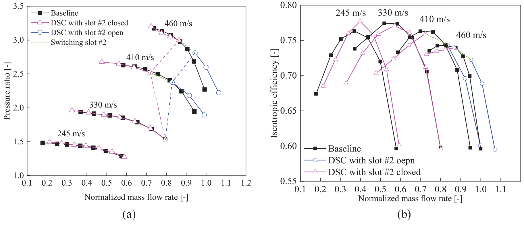
Experimental results of the dependence of the pressure ratio on the normalized mass flow rate obtained by the dual-port shroud with active switching function (DSC refers to the dual-ported shroud casing): (a) pressure ratio versus mass flow rate and (b) isentropic efficiency versus mass flow rate.
Figure 5(b) compares the compressor isentropic efficiencies, which are calculated according to the following equation,
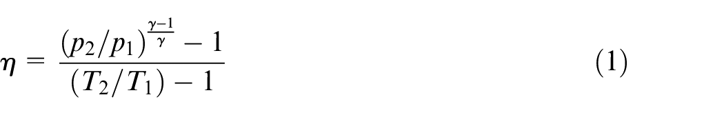
Where p1 and p2 represent the pressure at the inlet and outlet of a compressor, respectively. T1 and T2 are for the temperature at the inlet and outlet of a compressor, respectively. γ stands for the adiabatic exponent.
The comparison reveals noticeable reductions around the peak efficiency point at three high rotational speeds. The quantitative efficiency deteriorations are calculated around the peak efficiency region at each speed line to assess the efficiency change. As listed in Table 3, at the impeller exit speed of 245 m/s, the casing treatment raises the compressor efficiency by 1.36 percentage points but deteriorates it at other tested speeds. The speed of 245 m/s is far lower than the design speed, and the maximum efficiency degradation at such a speed should be attributed to the boundary layer separation. The cavity in the casing may mitigate the flow separation and thus contribute to the efficiency rise of 1.36 percentage points. However, at other speeds near the design speed, the cavity in the casing causes flow loss and then deteriorates the peak efficiency. It is concluded that the dual-ported shroud casing deteriorates the isentropic efficiency in the high-efficiency region of the compressor aerodynamic performance map.
Decrease of the peak efficiency at various speed lines.
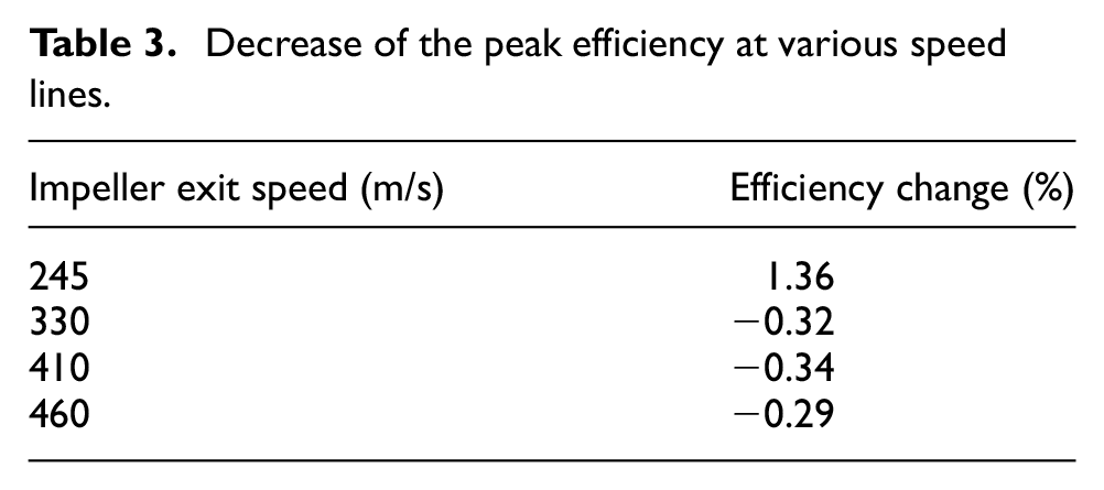
Figure 6 shows the static pressure distribution at the near-choke condition at the top rotational speed. A few low-pressure regions are observed in the impeller channels at the 98% span because of the flow acceleration. The first one is located at the impeller geometry throat that is guided by the adjacent main blades. Others can be observed at two sides of the splitter blade because the splitter blade further enhances the flow acceleration. On the meridian plane, the pitch-averaged static pressure distribution reveals a low-pressure region located just behind the LE of the splitter blades. Therefore, a significant pressure difference exists between the inlet duct and the low-pressure area.
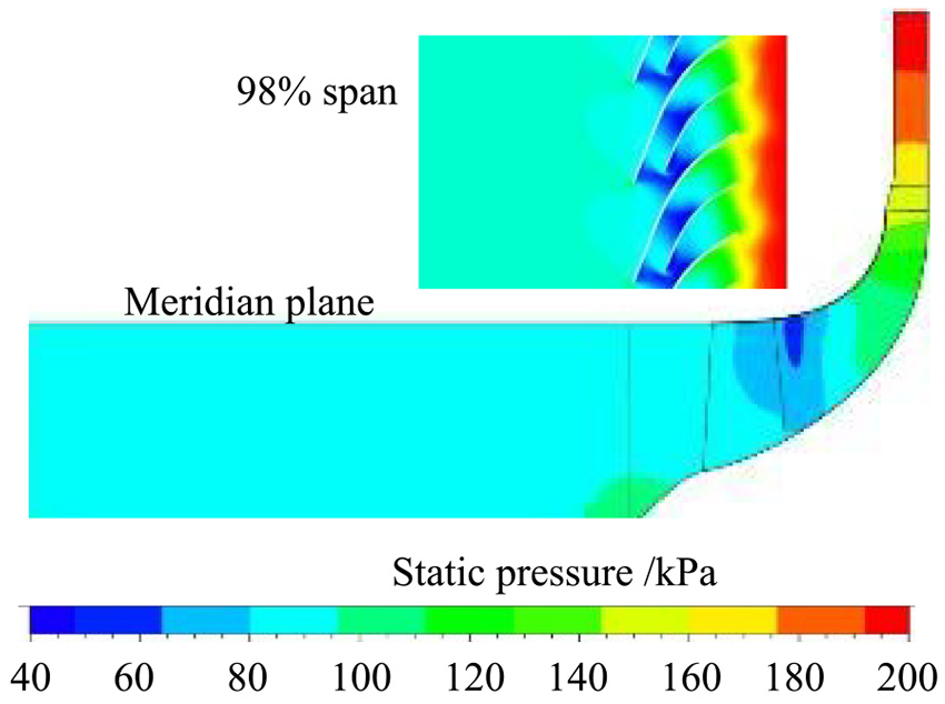
Numerical results of the static pressure distribution. (1) Pitch-average static pressure; (2) at 98% span (CFD results).
With the pressure difference, Slots #1 and #2 work at the same time but have different flow directions. Slot #1 still generates the self-circulating flow from the impeller blade tips to the inlet duct through slot #1. In contrast, slot #2 allows some air to enter the impeller blade tips from the inlet duct and works as a bypass passage, as presented by the streamlines in Figure 7. It is the novel phenomenon of the dual-port casing treatment.
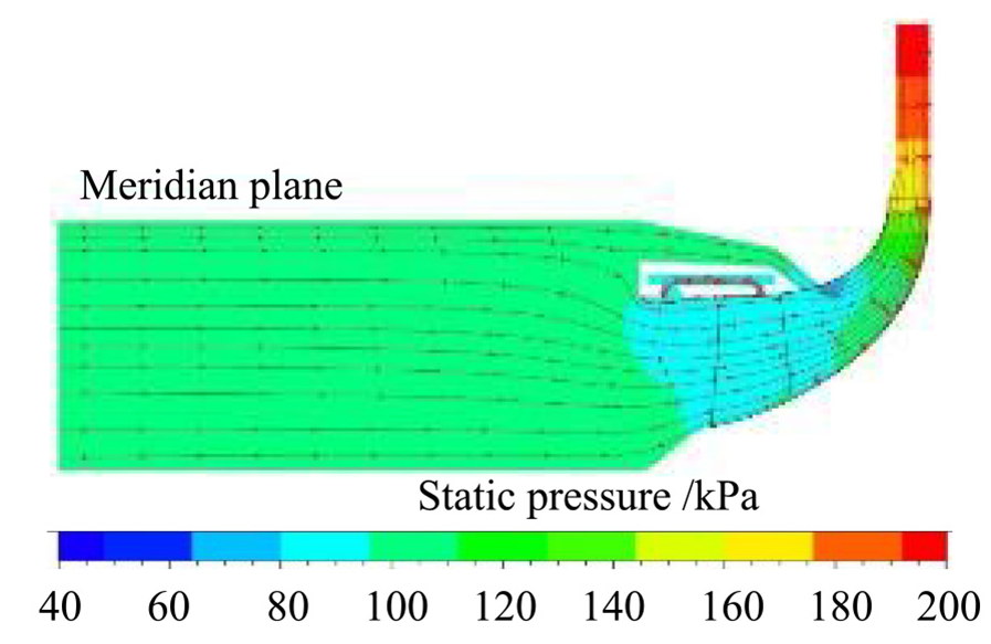
Distribution of static pressure with streamlines for the compressor with dual-ported shroud casing (CFD results). Dual-port casing treatment with slot #2 open at the near choking point.
In principle, slot #2 bypasses over the impeller throat. With the bypass function, some air flows enter the impeller without going through the inducer inlet. In the dual-port casing treatment compressor, the impeller choking flow rate is not determined only by the inducer throat when slot #2 is open. This is how the dual-ported shroud casing can increase the compressor choking flow capacity.
With the casing treatment, the compressor has an improved operating region. Table 4 lists the stable operating range rise (SORR), which is the relative value calculated according to,
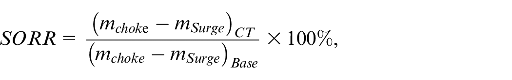
where m stands for the mass flow rate. The subscripts, CT and Base, represent the compressor with dual-port casing treatment and the baseline compressor, respectively. The mass flow rate at the chocking state is defined at the compressor isentropic efficiency of 60%.
Quantitative compressor changes with dual-port casing treatment against the baseline compressor (experimental results).
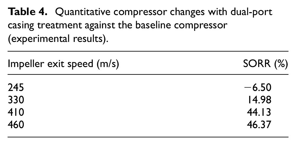
By repeating the calculation at four speed lines, we obtained four SORR values. At speeds of 410 and 460 m/s, SORRs are over 40%, far more significant than that at the speed of 330m/s. The high SORR obtained at the high-speed results from the increase in the choke flow capacity. In other words, the extension at two ends of the speed line is a significant advantage of the dual-port casing treatment over the traditional one. A turbocharged diesel engine always requires its turbocharger compressor to pump more air at high speeds to achieve rated power. Meanwhile, it also requires a low mass flow rate at the compressor surge boundary to improve the exhaust gas recirculation ratio at part-loading points.
Overall SPL analysis
Figure 8 presents the overall sound pressure level (OASPL) distributions of the experimental prototypes, the baseline and dual-port shroud compressors. The OASPL of the dual-port shroud compressor is higher than that of the other compressor, especially at the operating points where slot #2 is open.
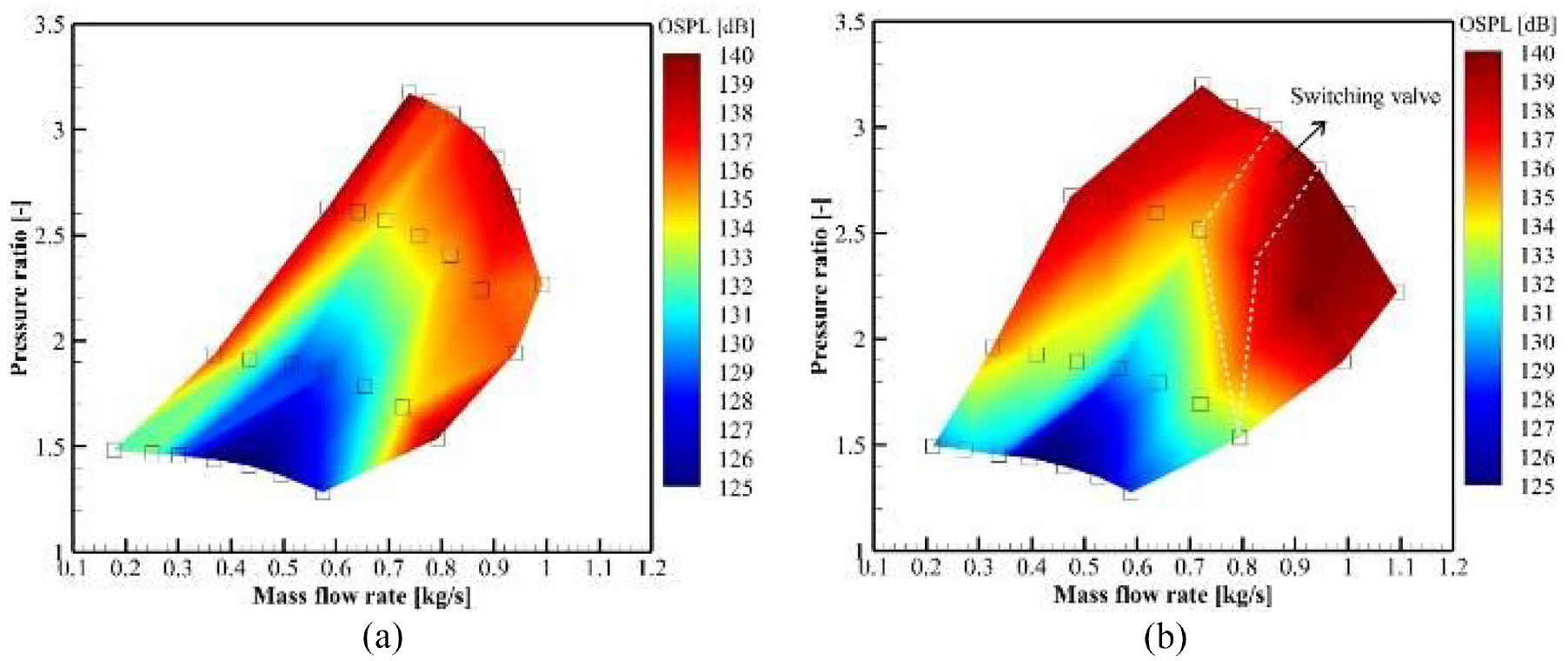
Comparison of the sound pressure levels of two configurations(experimental results): (a) baseline compressor and (b) dual-port compressor.
As a quantitative comparison, Figure 9 compares the OASPL acquired at the speed line of 410 m/s. At high flow rates, the compressor with dual-port casing treatment does correspond to higher OASPL values than the baseline compressor. The largest discrepancy is up to 3.8 dB. Therefore, it is concluded that the dual-port casing treatment leads to poorer aero-acoustic performance and is noisier at high mass flow rates.
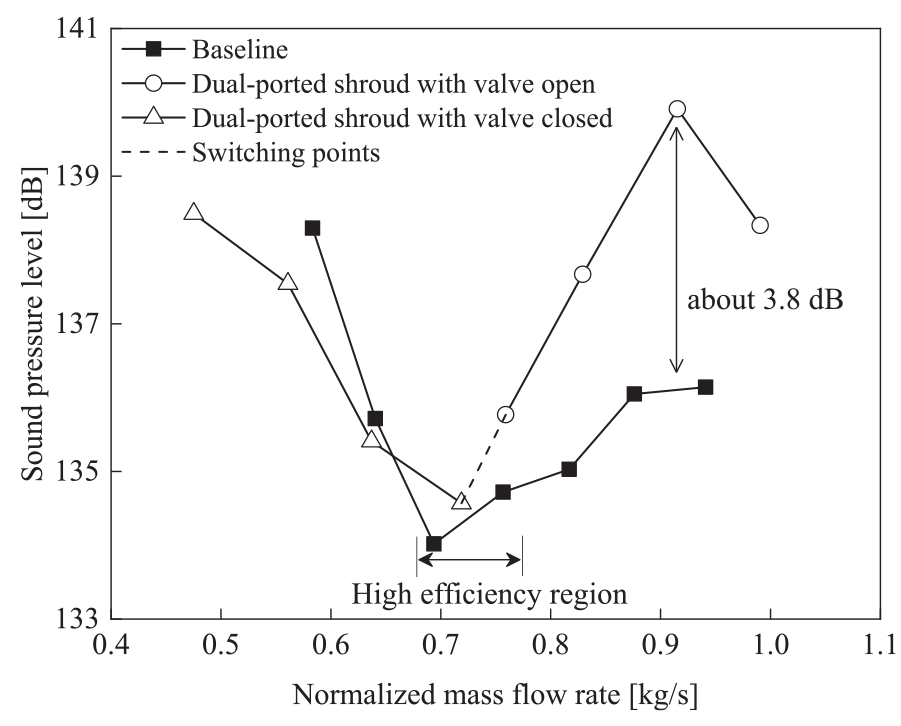
Comparison of the OASPL with the exit speed being 410 m/s (experimental results).
The noise increase at high flow rates is attributed to the opening of slot #2 for the compressor with the dual-port casing treatment. Opening slot #2 not only provides a bypass channel for air flows but also allows noise propagation. By propagating through the bypass channels in the shroud casing, the noise comes into the inlet duct from the impeller and mixes with the noise from the inducer inlet. Consequently, the sound reaches a higher level in the inlet duct of the compressor with dual-port casing treatment than in the baseline compressor inlet duct.
Within the high-efficiency region (as marked in Figure 9), the compressor with the dual-ports casing treatment has a larger noise in its inlet duct than the baseline compressor. This result is in agreement with the findings reported by Sharma et al. 21 They compared two configurations of a centrifugal compressor with and without a ported shroud and reported higher OASPL and tonal noise components in the compressor with the ported shroud casing operating.
At the left side of the high-efficiency region, the dual-port shroud casing has the slot #1 open and the slot #2 closed. Compared with the baseline compressor, slot #1 restrains the noise rising with the compressor mass flow rate reduction. For instance, although the sound of the dual-port shroud compressor grows with the compressor mass flow rate reduction, the trend is not as steep as that of the baseline compressor, thus resulting in a crossing of the two curves.
At the left side of the crossing point, the compressor with dual-port casing treatment has lower noise than the baseline compressor. As reported by Dehner et al., 22 the ported shroud can reduce the severe whoosh noise from the compressor without casing treatment. The whoosh noise occurs in the operating range from the mid-flow to the surge boundary and is generated by the interaction between the flow instability and the rotor blade.23,24 Therefore, the whoosh noise reduction resulting from the ported shroud utilization contributes to the lower OASPL of the compressor with dual-port casing treatment at the left side of the crossing point (as marked in Figure 9).
Noise spectrum analysis
Figure 10 compares the noise spectrum plots at the speed line of 410 m/s. The noise at the blade pass frequency (BPF) becomes higher when slot #2 is opened. So does the noise at the BPF harmonics, 15,000 Hz. The BPFs include the main blade passing frequency (5000 Hz) and the passing frequency of the main and splitter blades (10,000 Hz). As for the harmonics, only those lower than 20,000 Hz are considered in this paper. For two cases, the only change is the compressor casing cover, and slot #2 increases the narrow-band noise. The mechanism should be the additional path provided by opening slot #2.
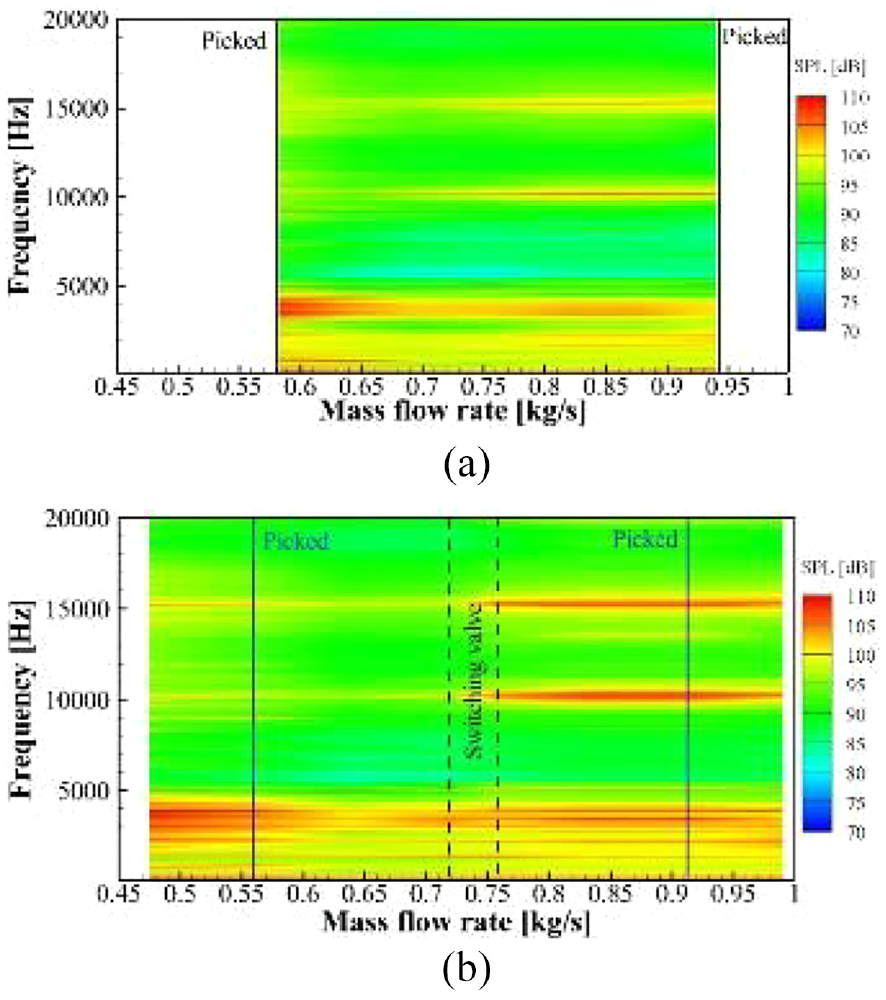
Comparison of compressor noise emission at the inlet, at the speed of 410 m/s, experimental results: (a) baseline compressor and (b) dual-port compressor with active switching valve.
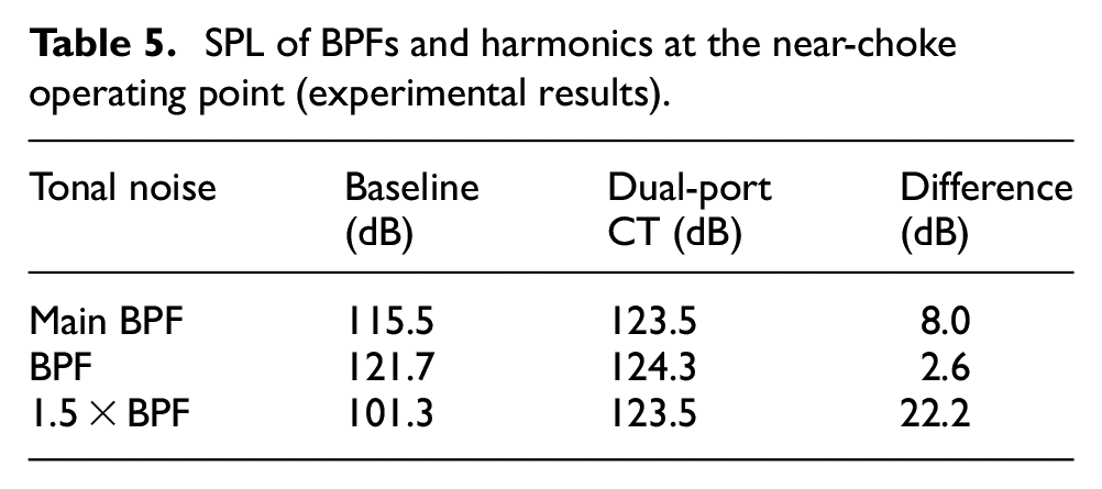
As a further quantitative comparison, Figure 11 presents the spectrum of the noise from the baseline and the dual-port compressors at the near-choke operating point (as marked in Figure 10). Table 5 lists the SPLs of those discrete tones. The maximum difference is 22.2 dB, occurring at the second harmonic frequency. The high peaks of the compressor with the dual-port casing treatment are evidence that the dual-port casing treatment increases the tonal noise at BPFs and their harmonics. The BPF noise and its harmonics are the main parts of the overall sound. Therefore, the increased noise at the BPFs and their harmonic frequencies explain the rising of the high OASPL at high mass flow rates where slot #2 is open.
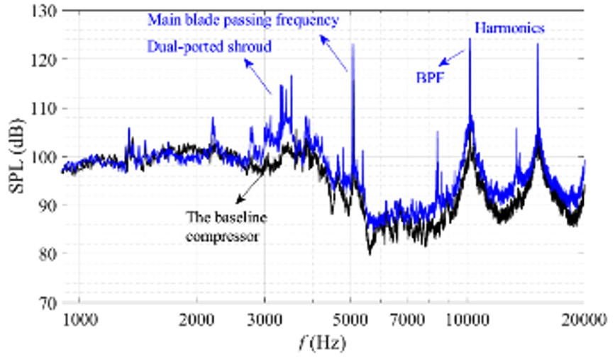
Comparison of the sound spectrum at the near choke operating point (marked in Figure 10; experimental results).
SPL of BPFs and harmonics at the near-choke operating point (experimental results).
In addition, a significant noise increase can be observed between 1500 Hz and 4000 Hz for the compressor with the dual-port casing treatment. The frequency band is the unpleasant and unwanted sound frequency according to the loudness, making the noise problem more significant for the compressor with the dual-port casing treatment.
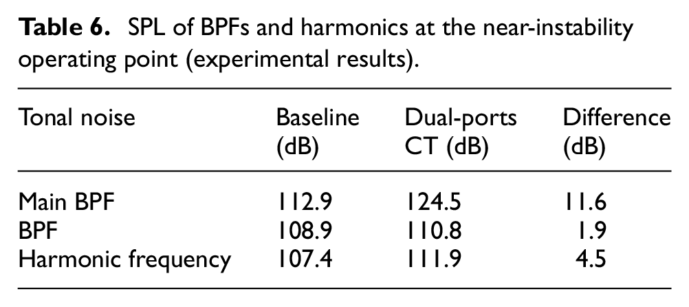
Near the instability boundary (the operating point is marked in Figure 10), slot #1 causes higher noise at the BPFs and their harmonics but lower sound at the shaft rotational frequency, as shown in Figure 12. Table 6 lists the quantitative sound rise and reports that the maximum difference occurs at the main BPF and is up to 11.6 dB. Compared with the baseline compressor, slot #1 provides one more path for the noise emission from the impeller to the compressor inlet duct. In other words, in the inlet duct of the compressor with the dual-port casing treatment, the BPF noise is subjected to the tones from the inducer inlet and slot #1.
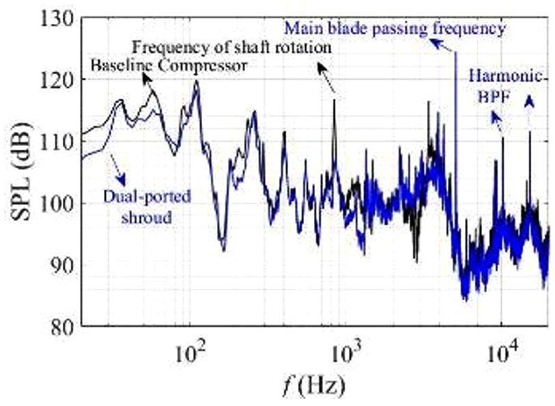
Comparison of the spectra at the near-surge operating point (marked in Figure 10; experimental results).
SPL of BPFs and harmonics at the near-instability operating point (experimental results).
Besides the discrete tones, spectra of the broadband noise with frequencies varying from 20 to 400 Hz are also plotted in Figure 12. The frequency range, lower than half of the shaft rotational frequency, is attributed to the boundary layer separation around the inducer. Pietroniro et al. 25 also stated the areas with the recirculations and backflow have high acoustic power values. The comparison reveals that the dual-port casing treatment lowers broadband noise within the low-frequency region and, because the casing treatment can remove the boundary layer separation by recirculating it through the casing treatment slot, supports the idea that the broadband noise results from the separating flow around the inducer. The OASPL assessment accounts for the broad- and the narrow-band noise. The broadband noise mitigates while the tonal noise increases. The consequence is that the compressor with the dual-port casing treatment has lower noise in its inlet duct at the near-surge point (the baseline compressor surge boundary), as depicted in Figure 9.
In short, the rotating impeller with the dual-port casing treatment having two slots open has a higher noise level, resulting in poor aero-acoustic performance at high mass flow rates. The noise rise occurs for tones at the BPFs, the harmonics of the BPF, and the broadband component. Between the middle of the aerodynamic map and the instability boundary, the dual-port casing treatment in which slot #1 open and slot #2 closed lowers the broadband noise within the frequency range of 20 to 400 Hz, but it increases the tonal noise at the BPFs and their harmonics, especially at the main BPF.
Conclusions
Since its first proposal, the ported shroud has been widely investigated and used in a centrifugal compressor. Most ported shrouds have only one port over the impeller section with a fixed geometry slot design in the shroud casing. In this paper, we investigate a dual-port shroud casing with two ports over the impeller section and report experimental results of the prototype test compressor, including the aerodynamic and aero-acoustic performance. The main findings are drawn as follows:
Experimental data reveals the novelty of the dual-port shroud casing. The dual-port casing treatment with an active switchable slot #2 enhances the compressor performance map width by improving the compressor surge margin and increasing the impeller flow capacity. By switching slot #2 according to the needs of compressor operation, the stable operating range of the compressor can be extended at both ends of the speed line, about 44.13% and 46.17% at the impeller exit blade tip speeds of 410 and 460 m/s, respectively.
The dual-ported shroud casing's bypass function increases the chocking flow capacity. A part of air can enter the impeller channels at the blade tips, rather than the inducer inlet, and thus is not limited by the geometry throat of the impeller. This is the mechanism by which the dual-ported shroud improves the compressor flow capacity.
The dual-port shroud compressor has a disadvantage in the aero-acoustic performance at high flow rates compared to the baseline compressor. The noise increases by up to 3.8 dB and occurs at the BPFs, the harmonics of the BPF, and the unpleasant frequency range of 1500–4000 Hz. It is attributed to the double ports in the shroud casing, which provide additional passages for the noise propagation to the inlet duct from the impeller, thus raising the sound intensity in the compressor inlet duct.
Footnotes
Appendix A
The cross-section sketch of the compressor prototype geometry is presented in Figure A1. Two slots are marked with arrows, upstream of which a valve is implemented. As the core part of the valve, there are two adjustable rings with a series of holes on each. By rotating one ring and fixing the other one, the flow areas of the holes can be continuously adjusted and hence the flow rate in Slot #2 can be changed.
Appendix B
Figure B1 plots the numerically predicted efficiency against the account of the grid points. The results were obtained by repeating the same numerical scheme on the computational mesh with various numbers of grid points. With the observation, the mesh with 1.44 million grid points was picked for simulation.
Figure B2 shows the computational mesh and the comparison of the numerically predicted compressor isentropic efficiency against the experimental data. The compressor has the same blade angles as the investigating object in this paper. The only difference in the compressor geometry is the diameter of the impeller. Therefore, the comparison conducted on a similar compressor partially supports the numerical scheme adopted in the paper.
Declaration of conflicting interests
The author(s) declared no potential conflicts of interest with respect to the research, authorship, and/or publication of this article.
Funding
The author(s) disclosed receipt of the following financial support for the research, authorship, and/or publication of this article: The authors thank the financial support from the National Natural Science Fundamental of China (Grant No. 52006217).