A wall-modelled large-eddy simulation (WMLES) method previously validated against laboratory experiments is applied to a real engine disc cavity geometry with surface and air temperatures representative of maximum power conditions. An appropriate set of independent nondimensional parameters describing the problem is defined and the sensitivities to these parameters are investigated by independently varying each parameter in the WMLES. Effects of a change in disc temperature distribution and a reduction in radius of the downstream disc are also investigated. The flow and heat transfer mechanisms predicted are very similar to those found for the research rig configuration although rotating cavity flow structures with two or more lobes are found for the engine geometry rather than the single-lobed structures shown in previous work. The simulations are compared with an elementary model giving further insight into scaling of the flow and heat transfer with operating conditions. The model assumes a well-mixed core flow in the cavity with constant rothalpy, relates shroud heat transfer to that of natural convection under gravity for high Rayleigh number, and relates disc heat transfer to conduction across unsteady Ekman layers. An energy balance for the cavity is used to obtain an effective mass flow exchange rate between the axial throughflow and the disc cavity to the disc and shroud heat transfer and core temperature. The model is considered to give a useful basis for engineering calculations involving correlation and extrapolation of WMLES and experimental results.
Disc heat transfer in axial compressors is important because it affects blade tip clearances and component life in gas turbine engines. Rotating annular cavities are formed between adjacent, rotating discs and the shroud and centrifugal buoyant flow in the cavity may interact with cooling air supplied as an axial throughflow at the disc bore. This has long been recognised as a challenging flow problem featuring three-dimensional, unsteady and unstable flows. However, recent research has clarified the flow and heat transfer mechanisms involved and established wall-modelled large-eddy simulation (WMLES) as a potential tool for use in industry.1 This paper builds on recent work, WMLES is applied to investigate flow in an engine disc cavity geometry, and examine sensitivity of heat transfer to variations in controlling nondimensional parameters. The simulation results are related to an elementary model of the type suitable for use in large-scale industrial thermo-mechanical models.
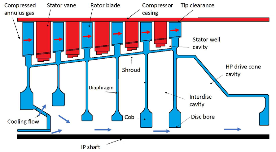
Figure 1 shows rotating disc cavities in a typical high pressure drum arrangement with cooling secondary air delivered to downstream components. Typically, cooling flow from a lower pressure compressor stage flows axially between the high pressure compressor disc bores and a low or intermediate pressure shaft. However, compressor rotating disc cavities with radial inflow or no forced axial throughflow, and closed cavities are found in other engine configurations. At stabilised running conditions the higher temperature of the compressed air in the main annulus compared to the axial throughflow generates a positive radial temperature gradient in the discs and shroud. Following an engine acceleration or deceleration the disc and shroud temperatures take longer to adjust than the main annulus gas and the form of the surface temperature distribution changes significantly. Negative disc temperature gradients may occur following an engine deceleration when the disc cobs may take longer to cool than the shroud.
Typical high pressure compressor disc cavities.
In industry thermal modelling of compressor drums is used in estimating component life and running clearances. Thermal stresses and thermal expansion both contribute to total rotating disc stresses and distortion, with the time-scales for thermal effects being much longer than for rotational effects. Stationary component distortion is not subject to centrifugal growth and blade tip clearances must accommodate the difference between rotor and stator movements. These may be particularly severe following a change of engine speed. Typical aeroengine thermal modelling requirements and practices are described by Dixon et al.2 Although the use of CFD in industry has continued to increase there is still considerable reliance on relatively simple formulae for scaling of heat transfer correlations through a flight cycle, from laboratory to engine conditions, from one engine design to another, or from CFD solutions for a limited number of conditions.
As previous research has been discussed in the papers mentioned below, only the most directly relevant studies are discussed here. Complementary simulation and experimental research have recently provided a clear picture of flow and heat transfer in co-rotating disc cavities, including details of the levels of unsteadiness and turbulence in the cavity flow and the nature of the disc boundary layers. Centrifugal convection in a closed rotating cavity has provided a useful test case and is directly relevant to some engine configurations. Earlier numerical and experimental results for this case (assuming laminar flow or Reynold-averaged models of turbulence) suffered from considerable uncertainty and mixed results were obtained. More recently, direct numerical simulations (DNS) and large-eddy simulations (LES) from four different codes show similar Nusselt-Rayleigh number scaling and levels of heat transfer for the closed cavity (where assumed conditions correspond or are close) and this is also confirmed by recent measurements.3–6 An interesting feature of the simulations is that, although the flow in the core is turbulent at high Rayleigh numbers, the Ekman layers on the discs remained laminar for all cases considered. These Ekman layers are highly unsteady, rapidly responding to large scale unsteadiness in the core flow. The mean flow transport in the layers is weak compared to their unsteady component.3
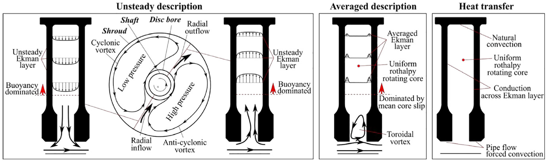
For cavities with axial throughflow, recent LES results have been reported in Refs.1,7,8 Saini and Sandberg7 give results for cases with Rossby number and rotational Reynolds number using wall-resolved LES. Gao and Chew1 give results for cases with to and to using wall-modelled LES, and include comparison with recent experimental data from the University of Bath.9–12 Sun et al.8 explore low Rossby number effects, extending simulation of the Bath configuration to and . The interpretations of the flow and heat transfer mechanisms from Gao and Chew1 are summarised in Figure 2 and will be discussed further in the present paper. A point to note is that the ratio of kinetic energy effects to enthalpy changes, as represented by an Eckert number, can be significant. Hence it is convenient to use the rotary stagnation temperature , where is rothalpy and is specific heat at constant pressure, in defining and analysing the problem. Rothalpy is defined as , where is static temperature, is velocity in a rotating frame of reference with angular velocity , and is radius. It is comparable to total enthalpy in a stationary system. Rothalpy is conserved along streamlines in steady, inviscid, adiabatic flow and conserved in steady flow systems with no net heat transfer or work done in the rotating frame.
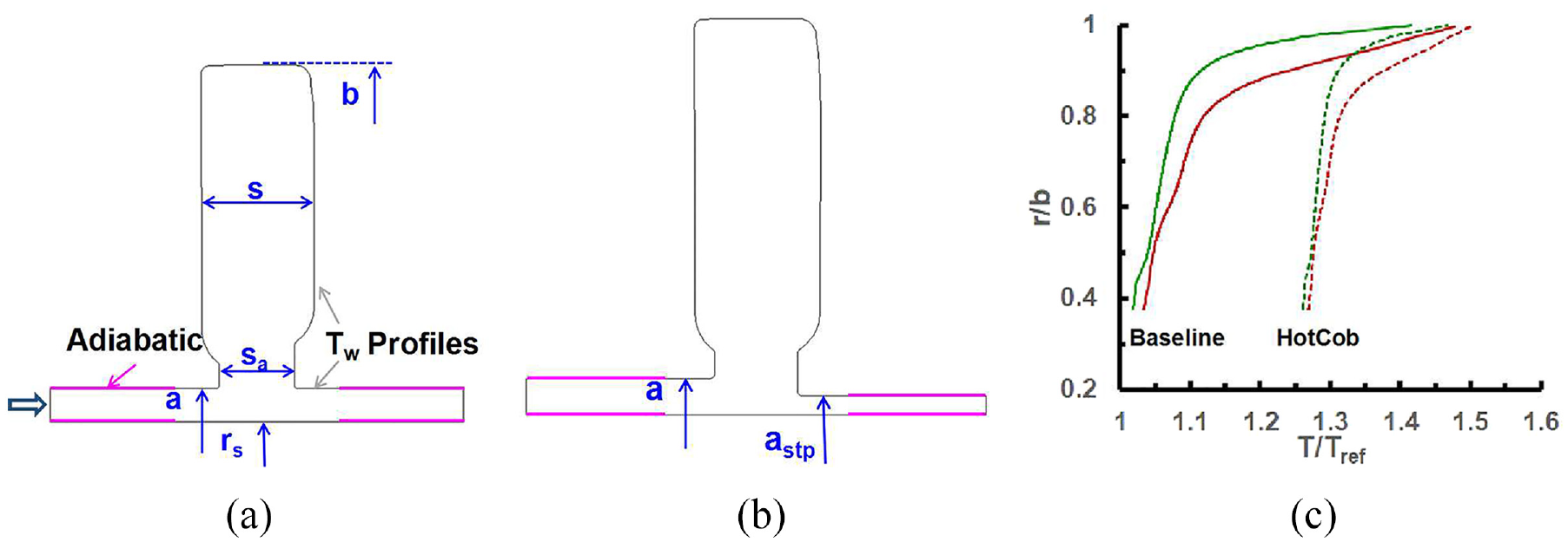
In the present study the flow and heat transfer for the cavity geometry shown in Figure 3 are studied using WMLES, with consideration of scaling as operating conditions change and elementary modelling. The cavity geometry used corresponds to that for a single stage in a modern civil aeroengine, but is modelled in isolation rather than in the multicavity arrangement in the engine. The baseline surface temperature distribution given is as estimated for the engine at a stabilised high power condition from an industrial thermal model. Complete nondimensional conditions are given but these do not correspond directly to an engine running condition. The study was conducted at a rotational Reynolds number of which is more typical of research rigs than aeroengine operating conditions. This considerably reduced the computing resources required allowing more conditions to be investigated in the time available. Key nondimensional geometric parameters, following the notation in Figure 3, are , , , and .
The baseline compressor disc cavity (a), stepped bore geometry (b) and nondimensional disc temperature distributions (c).
Before presenting the WMLES, nondimensionalisation and elementary modelling are considered in sections 2 and 3 of the paper. Section 4 describes the numerical methods and implementation of the WMLES. Results of the WMLES, alongside comparisons with the elementary model are given in section 5. This includes discussion of the flow structure, heat transfer and mass and energy exchange between the throughflow and the main cavity. The main conclusions from the study are summarised in section 6.
Parametric characterisation
Dimensional analysis for flow and heat transfer for a perfect gas in geometrically similar cavity configurations is considered. It is further assumed that surface temperature distributions are characterised by a single inlet-to-shroud temperature difference . It may then be supposed, for example, that the shroud heat transfer is a function of disc radius , disc rotational speed , shaft rotational speed , inflow mean axial velocity , inflow mean swirl velocity at the bore inlet, representative temperature , representative density , viscosity , thermal conductivity of the cavity flow, shroud-to-inlet rotary stagnation temperature difference , specific heat and ratio of specific heats . Hence
where is an unknown function. This equation gives as a function of 12 parameters involving the four fundamental dimensions length, time, mass and temperature. Following the Buckingham pi theorem, a nondimensional shroud heat flux, such as the shroud Nusselt number, can be written as a function of just eight independent nondimensional parameters. The selection of these eight nondimensionals is subject to some restrictions but is arbitrary to a large extent. The parameters chosen here and the rationale for this are given below.
Prandtl number = Restricting the study to air, can, to a good approximation, be assumed constant.
Ratio of specific heats = where is specific heat at constant volume. As for , is assumed constant for air.
Shaft-to-disc speed ratio : Long and Childs13 reported that shaft rotation had limited impact on heat transfer in their experiments. Hence the effect of varying the speed ratio has not been investigated in this study.
Buoyancy parameter where the thermal expansion coefficient , could be chosen as (as an approximation for a perfect gas), and is the shroud-to-inlet rotary stagnation temperature difference which drives the buoyancy effects. This parameter is also assumed to characterise (as an approximation) the fluid viscosity and thermal conductivity dependence on temperature.
Rotational Reynolds number = with , , and denoting reference density, rotor speed, shroud radius and reference viscosity. Scaling with Reynolds number is of particular interest. Laboratory experiments and high-fidelity CFD studies are often conducted at lower Reynolds number than occur in engines, and varies considerable between idle and maximum power in engine operations.
Rossby number = where is the bulk axial velocity at the bore inlet and is the disc inner radius, as illustrated in Figure 3. This velocity ratio is used here to characterise the strength of the axial throughflow. The inner cavity radius a has been used here rather than the outer radius b chosen as the representative length above. As geometric similarity is assumed the ratio a/b is fixed and a Rossby number based on the length scale b would differ from that used by a constant factor. In a more general treatment a/b and other nondimensional geometrical parameters would be included as independent parameters.
Eckert number = , where is specific heat at constant pressure and is static temperature, is used to characterise the ratio of kinetic energy to enthalpy changes. Combined with the other independent nondimensionals can be used to find a representative Mach number, and so can be considered as characterising compressible flow effects. However, also reflects the strength of work transfer and frictional energy transfer in the fluid. As suggested by Gao and Chew1,14 it may be possible to account for Eckert number effects by assuming differences in rotary stagnation temperature drive the heat transfer. For low enough values of the static temperature and rotary stagnation temperature can be considered equal.
Inlet swirl ratio where is the mean inlet swirl velocity. In many engine configurations the throughflow will be introduced to the bore with significant over, or under swirl compared to the rotor, and swirl velocity will adjust as the flow passes through upstream disc cavities. Hence the sensitivity of flow and heat transfer to this parameter is of interest.
Thus, effects of the five independent parameters , , , and are considered below. In addition, the effects of a change in disc temperature profiles (raising the temperature of the cobs) and of a reduction in the inner radius of the downstream disc are investigated.
Elementary model
An elementary treatment of the cavity heat transfer, relevant at stabilised high power conditions, is indicated in Figure 2. A well-mixed, uniform rothalpy core with centrifugal Rayleigh-Bénard convection to the shroud and heat conduction to the discs across laminar Ekman layers is assumed, as indicated in the description of averaged flow and heat transfer in the figure. In addition, energy transfer between the core and the axial throughflow is associated with mass flow exchange. For the baseline disc temperature distribution shown in Figure 3 the heat transfer on the disc cob faces is relatively low and the placement of the inner boundary of the core within this range makes little difference. Hence the boundary at the disc bore radius is used here. For conditions with higher cob heat transfer it may be necessary to move this boundary radially outwards and treat the cob heat transfer separately. Denoting the core rotary stagnation temperature by and assuming a fully mixed core exchanging fluid with the axial throughflow at rate with the bore inlet temperature and the cavity outflow temperature an energy balance gives the following equation
where is the total heat transfer from the disc and shroud cavity surfaces. Note that with the use of rotary stagnation temperature this equation takes account of the work done to maintain the rotor speed.
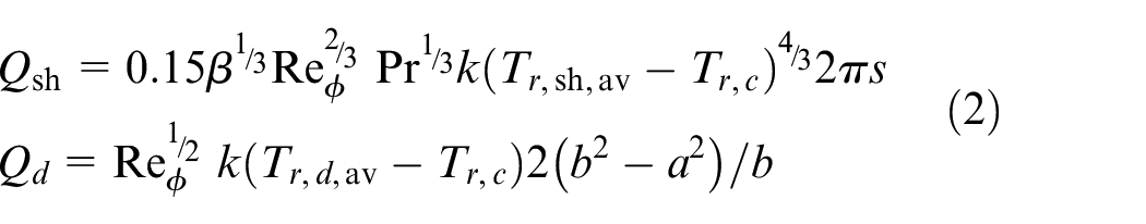
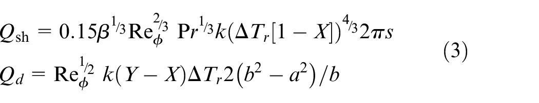
Splitting the cavity surface heat flux into contributions from the shroud and discs with application of a standard (high Rayleigh number) natural convection correlation and Ekman layer theory, as described in Gao and Chew,1 gives
Here is the shroud width, assumed equal to the cavity width, and includes contributions from both discs. Area averaged temperatures are used for the discs and shroud, assuming relatively weak variation of shroud temperature over the surface and neglecting the effect of temperature and pressure on fluid properties. These equations are based on evaluation of previous CFD and experimental studies. Further support for their use is given later in this paper and further ‘correction factors’ to these equations, as might be used in matching thermal models to test data, could easily be included. Previous work6 has also considered the effects of frictional energy dissipation and possible transition to turbulence in the Ekman layers at higher Reynolds number. These are considered negligible for the conditions studied in this paper and so are not included in the model here. In extrapolating to very high Reynolds numbers these effects could become significant.
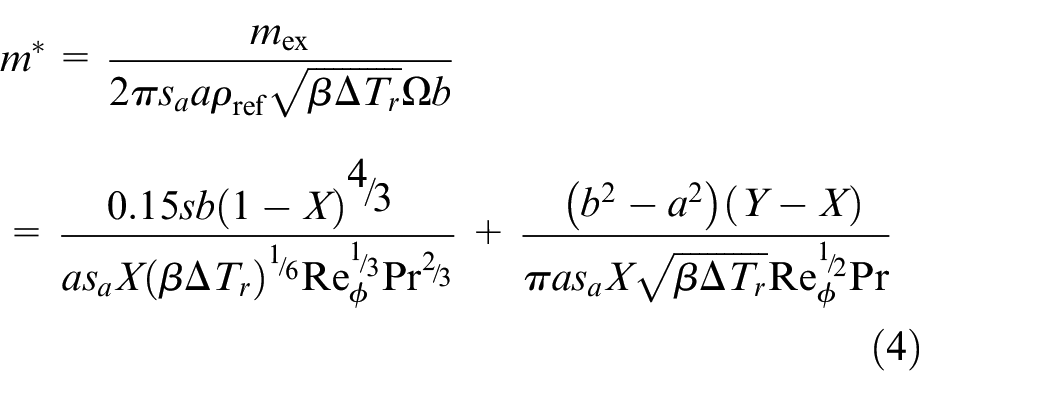
Defining nondimensional core and area-averaged disc temperatures and equations (2) can be rewritten as
where is the nondimensional exchange flow rate, utilising the velocity scale associated with buoyancy and the area available for flow exchange at the disc bore radius.
The first and second terms on the right-hand-side of equation (4) relate to the shroud and disc heat transfer, respectively. An immediate observation is that the relative strength of these terms varies with conditions. In particular, the proportion of the heat transfer occurring on the shroud increases with Reynolds number. This has implications in considering extrapolation of lower Reynolds number experiments to engine conditions.
For a given geometry, surface temperature distribution, and operating conditions (defined by the independent nondimensionals discussed above) equation (4) gives the exchange flow rate as a function of the core temperature , or vice versa. Thus specifying either or at a given operating point would give estimates of the disc and shroud heat transfer. Measurements of core temperature were reported for a cavity between plain discs with and by Long and Tucker.15 These indicate core temperatures in the range 0.2–0.3 for cases with a heated shroud and unheated discs and in the range 0.3–0.4 for cases with heated shrouds and discs. Based on a more engine representative multi-cavity geometry with shroud heating, , Long and Childs13 deduced values of in the range 0.2–0.4 by matching shroud heat transfer measurements to a natural convection correlation over a relatively broad range of operating conditions with in the range to and in the range 0.27–6.7. For Luberti et al.’s experimental configuration with , Gao and Chew1 found values of to be in region of 0.2. Core temperatures and exchange flow rates are further discussed later in the paper.
Numerical simulation
Numerical methods
The simulations use the Hydra CFD code developed by Rolls-Royce plc and its partners as described by Amirante and Hills.16 This is a compressible flow solver, using finite volume discretisation on unstructured node-vertex grids. A modified Roe scheme with a linear reconstruction technique for primitive variables is used to guarantee second-order spatial accuracy. Fourth-order artificial viscosity is used and set to the minimum value that stabilises the simulation. A three-step Runge-Kutta scheme is used to advance the solution in time. The subgrid-scale turbulence is simulated using the Smagorinsky model with a near-wall van Driest damping function. For the wall-modelled LES (WMLES) a wall function is used at near-wall mesh points. The wall function assumes standard relations for logarithmic, buffer and laminar sublayers, and is applied to the instantaneous flow. When the near-wall mesh spacing is sufficiently low the treatment reverts to that for a resolved near-wall mesh. This modelling approach is much more efficient than wall resolved LES and has been shown to be effective for the type of flows considered here in previous studies. Further description and validation of the WMLES are given in Refs.1,8,14
A full annulus 360° CFD model was employed. The mesh used was generated using the guidelines and practice developed in previous studies.1,14 The mesh resolution away from the walls is close to that of a wall-resolved model and is restricted by requirements for the nondimensional tangential mesh spacings at the wall. The near-wall mesh spacing normal to the wall is set to the minimum of the Ekman layer depth and an a priori estimate for . The total number of hexahedral cells is ∼9.4 million with 650 mesh planes uniformly distributed in the circumferential direction. This is similar to the ∼9 million cell mesh used in Gao and Chew1 for test cases with . For the baseline solution of Case-A described below, the average non-dimensional wall distance based on the mean flow obtained on cavity discs and shroud is around . Instantaneous values of may vary considerably. Laminar Ekman layers have been shown to occur in previous studies and, as expected, is relatively low for the disc surfaces. In the cavity core region typical mesh spacings are , and in the axial, radial and circumferential directions, respectively. The mesh rotated with the discs and shroud. The time step used was determined by trial and error in the actual simulations. In Case-A for example, the explicit time step corresponds to the time required for the disc to rotate 1/32,000th of a revolution. The resultant CFL was about 1.
A non-reflective boundary condition with specified static pressure was applied at the flow outlet. The inlet boundary conditions assumed a uniform total pressure, total temperature and swirl fraction, with the total pressure adjusted to match the target mass flow rate. No turbulence was specified at the flow inlet. No-slip, no-penetration, aerodynamically smooth wall conditions were applied on other boundaries. Apart from the shaft these rotate at speed . A counter rotating shaft with shaft-to-disc speed ratio was assumed. Temperatures were specified on the shroud, disc faces and disc bores. Other solid surfaces in the CFD domain were assumed to be adiabatic.
The simulations were initialised with partially converged, steady Reynolds-averaged Navier-Stokes solutions. For each case, following an initial WMLES of 100 disc revolutions flow statistics were gathered over a further 100 revolutions. This sampling period corresponds to roughly three revolutions of the main cavity flow structure, as an approximately 3% core slip velocity was found in the present study. Typical computing time was approximately 8 days using 1600 Intel Xeon Gold 6148 CPU cores of a modern Linux cluster. Overall mass, momentum and energy balances were checked and found to be similar to that achieved in Gao and Chew.1 It was reported in Gao and Chew1 that errors in the energy balance rose to ∼20% of the cavity heat flux for some conditions, and this level was observed in the present study. However, these errors correspond to a relatively small percentage of the driving temperature difference between the hot shroud and the cold cooling inflow. Taking the baseline Case-A for example, the energy imbalance was equivalent to 2.1% of the inlet-to-shroud temperature difference. The mass flow imbalance for all nine test cases was good, below 0.1% of the mass flow rate at inlet.
Conditions considered
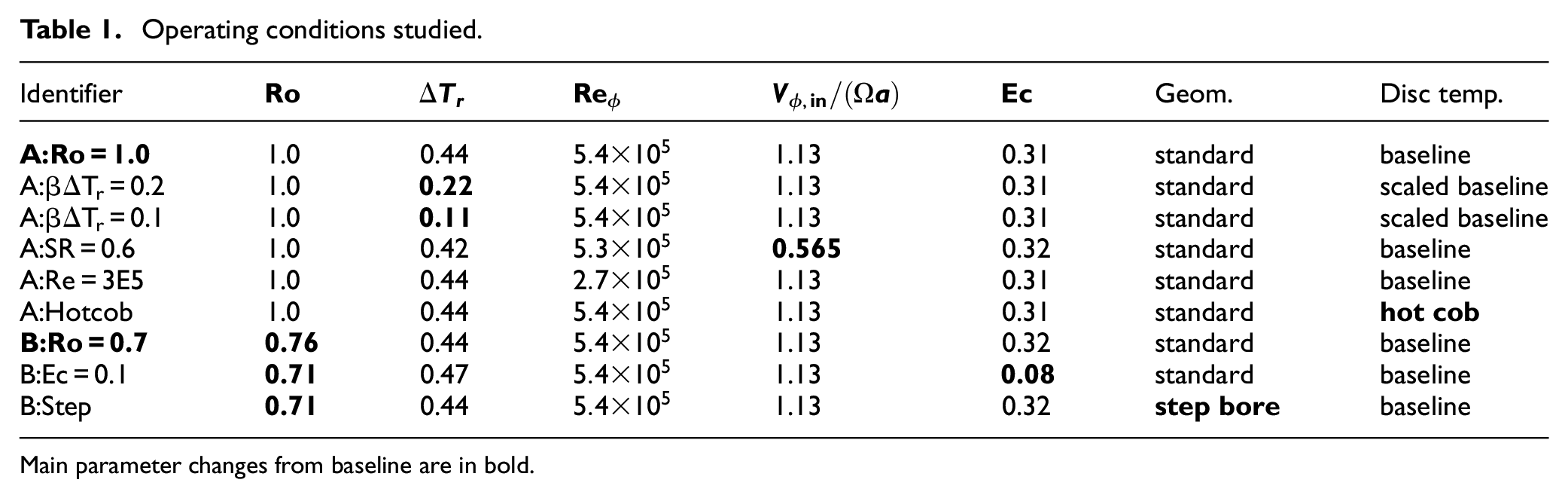
The WMLES assumes fluid properties for air modelled as a perfect gas with constant , and and with viscosity depending on temperature according to Sutherland’s law. The five nondimensional parameters selected in section 2 were varied, as summarised in Table 1. These variations were achieved in the simulations by varying the dimensional pressure level, shroud-to-inlet temperature difference, mass flow rate, disc speed, and inlet swirl velocity.
Case A:Ro = 1.0 in the second row of the table, gives a baseline condition with . In the four cases immediately below this just one nondimensional parameter, either , or , varies from case A, with the disc and shroud temperature distributions scaled where necessary to accommodate changes in shroud-to-inlet temperature. The identifiers for these cases start with A and indicate the main parameter changed and its approximate new value. For the case A:Hotcob, all five nondimensionals retain the values for case A:Ro = 1.0 but the disc temperature distribution is modified as shown in Figure 3. This could represent a transient engine case following deceleration, where the disc temperature has not yet cooled to thermodynamic equilibrium with the bore flow.
Case B:Ro = 0.7 differs from case A:Ro = 1.0 only in having a lower Rossby number. A reduced Eckert number condition, case B:Ec = 0.1, and the effect of the step in disc bore diameter, case B:step, shown in Figure 3 were investigated at a similar value of .
Operating conditions studied.
Identifier
Geom.
Disc temp.
A:Ro = 1.0
1.0
0.44
1.13
0.31
standard
baseline
A:βΔTr = 0.2
1.0
0.22
1.13
0.31
standard
scaled baseline
A:βΔTr = 0.1
1.0
0.11
1.13
0.31
standard
scaled baseline
A:SR = 0.6
1.0
0.42
0.565
0.32
standard
baseline
A:Re = 3E5
1.0
0.44
1.13
0.31
standard
baseline
A:Hotcob
1.0
0.44
1.13
0.31
standard
hot cob
B:Ro = 0.7
0.76
0.44
1.13
0.32
standard
baseline
B:Ec = 0.1
0.71
0.47
1.13
0.08
standard
baseline
B:Step
0.71
0.44
1.13
0.32
step bore
baseline
Main parameter changes from baseline are in bold.
Note, for example, that in laboratory experiments at atmospheric pressure Reynolds number is often varied by adjusting the rotor speed. This also changes the Eckert number. In the CFD study Reynolds number can be varied by adjusting the pressure level. This allows the effect of the different nondimensional parameters to be de-coupled.
Results
Flow structure
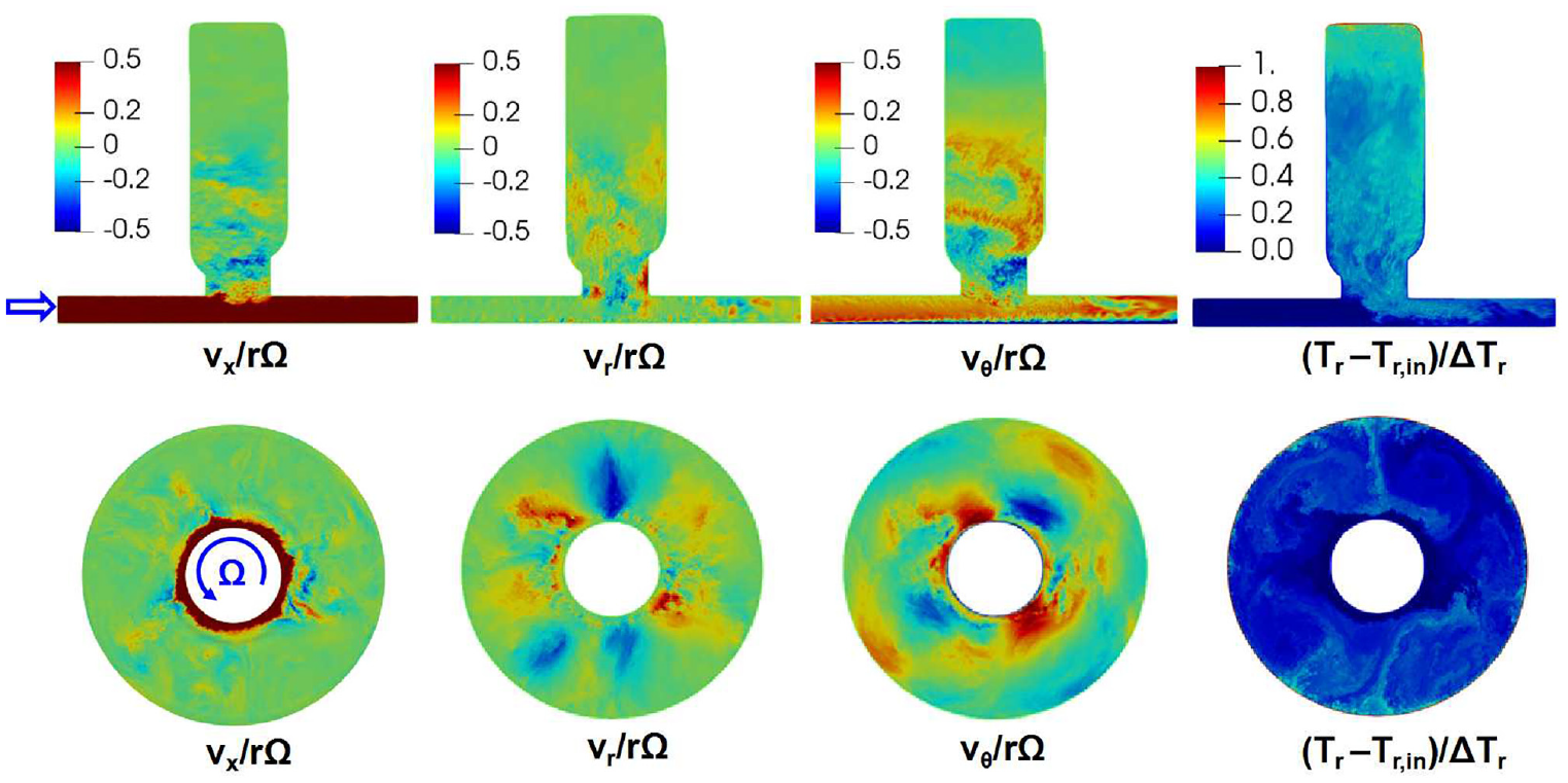
The instantaneous flow for case B:Ro = 0.7 in Table 1 is illustrated by the velocity and temperature contours in Figure 4. Note that these are just a snapshot of complex flow structures which change with time. Here the axial flow is from left to right in the angular plane view and the discs rotate anticlockwise in the axial plane view. The flow structure is qualitatively similar to that for the rig geometry shown in Figure 2, with the most noticeable difference being the presence of two or more anticyclonic/cyclonic vortex pairs rather than the single pair of vortices found for the laboratory rig geometry. This may be associated with the different disc cob geometries and higher hub-to-shroud radius ratio, , and gap ratio, , in the present configuration compared to and for the Bath rig. The contra-rotating shaft and higher inlet swirl in the present configuration could also contribute to destabilisation of the axial flow. The boundary layer on the contra-rotating shaft is evident in the tangential velocity contours. Within the cavity, axial gradients of the radial and circumferential velocities are relatively weak compared to the circumferential gradients, reflecting the Taylor-Proudman theorem for rotating flow. There is clearly considerable mass interchange between the cavity and the throughflow, cooling the discs and shrouds. Unsteadiness in the axial throughflow is also evident, particularly downstream of the cavity, and extends to the inlet and outlet.
Instantaneous flow contours for case B:Ro = 0.7 on an angular plane and the cavity mid-axial plane.
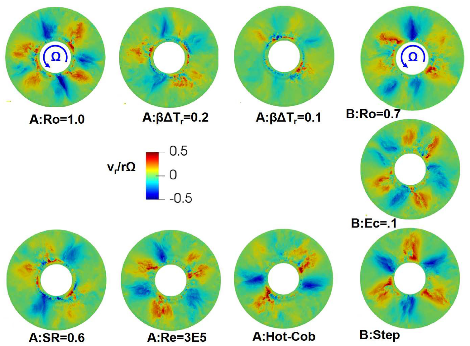
Instantaneous contours of radial velocity on the cavity mid-axial plane are shown for all nine cases considered in Figure 5. These show that 2, 3 or 4 vortex pairs may be present with varying degrees of coherence. When interpreting these it should be noted that the number of vortices can change with time. The clearest trend shown is the weakening of flow strength as is reduced. This is expected as buoyancy dominates the flow in the cavity core. The most distinct flow structure is perhaps the three vortex pairs for case B:Step, suggesting that the introduction of the step stabilises the flow structure.
Instantaneous radial velocities on the cavity mid-axial plane for all conditions in Table 1.
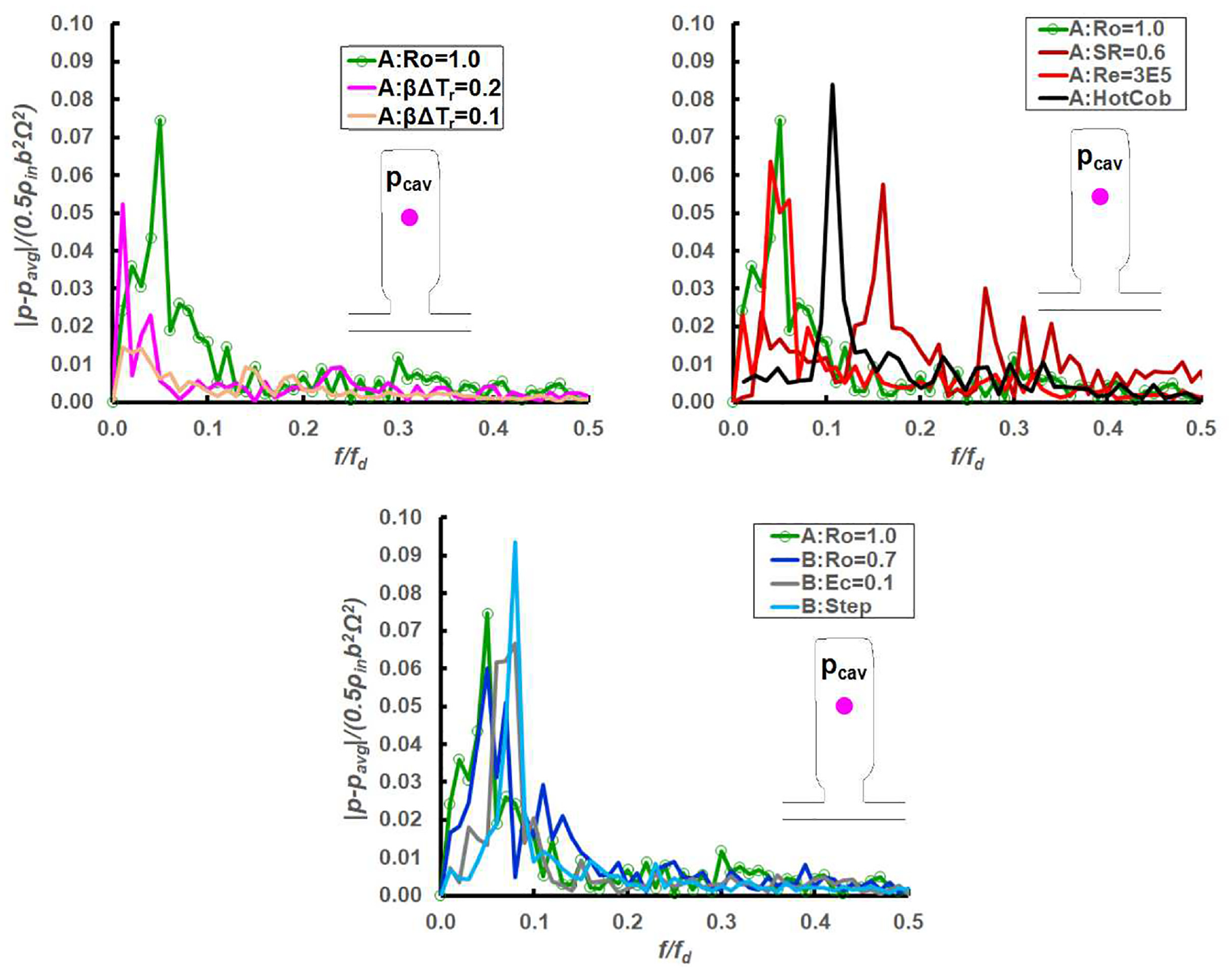
Figure 6 shows Fourier spectra for pressure monitors in the rotating frame of reference at the mid-axial position for . For each test case, the pressure monitors at the mid radius were recorded at three angular positions of θ = 0°, 5° and 30° simultaneously, following the practice in Gao and Chew1 and Sun et al.8 Their FFTs were checked for consistency and their averages are presented in the figure. Results are presented in three groups, with the baseline test case being used as a common reference. The pressure fluctuation amplitude is normalised by the disc rim dynamic head and the frequency is divided by rotor frequency. All the FFT results were obtained from data for 100 disc revolutions in one window without zero-padding. To highlight the major frequencies of the energy-containing flow structures, only results in the low frequency band are presented. The first group of results shows the effect of the buoyancy parameter on the cavity flow. Both the frequency and amplitude of the strongest flow fluctuations decrease as is reduced. The existence of other peak frequencies with lower amplitudes may reflect the changes in number of flow structures with time, as observed in flow visualisations.
Comparison of FFT results for all conditions in Table 1.
From the second graph in Figure 6, it appears that inlet swirl ratio and disc temperature have significant effects on the unsteady flow structure. The hot cob produces a more distinct main frequency, while reducing swirl ratio leads to higher frequency activity (which may be associated with greater slip between the main flow structure and the discs). Reducing Reynolds number weakens the unsteadiness slightly but has relatively little effect on the frequency. The third group of FFTs indicates that a reduction in Rossby number or Eckert number has limited effect on flow frequencies and amplitudes. For the test case with a stepped cob the spectrum shows a distinct peak at , corresponding to the definite three-lobed structure in Figure 5.
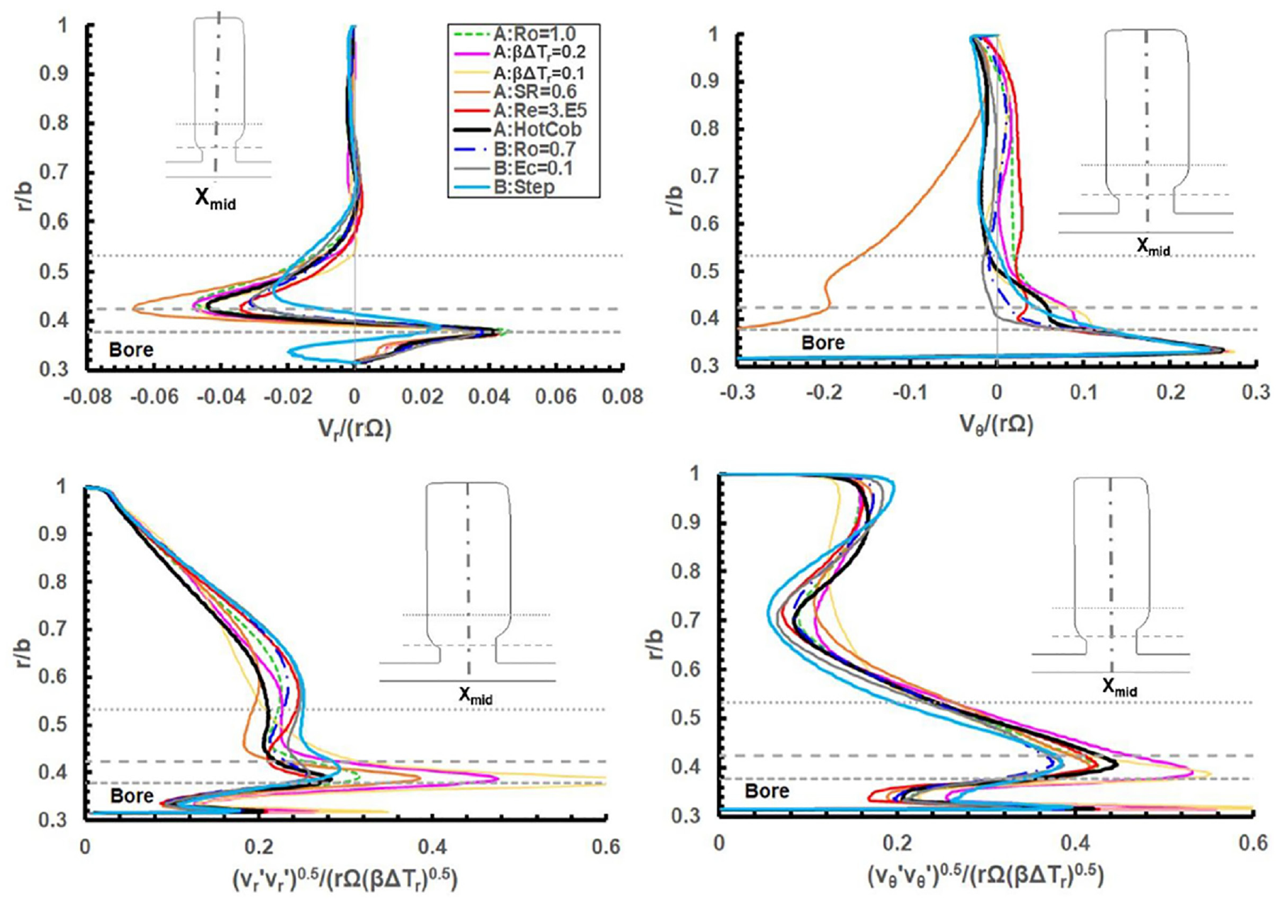
Further quantitative comparison of the flow fields for the different conditions is given by the profiles of mean and rms fluctuations of circumferential and radial velocities on the cavity mid-axial plane in Figure 7. These results are obtained from circumferential and time averaging. The horizontal dashed and dotted lines in these graphs give the radial positions of the disc bore, the outer corner of the cob on the upstream disc, and the blend point for the cob and disc web on the downstream disc, as illustrated in the figure. In the outer part of the cavity, for , the mean flow in most cases is close to solid body rotation at the disc speed. The exception is case A:SR = 0.6 for which the reduced inlet swirl produces a slip velocity of about at which reduces at higher radii. Apart from this case the main sensitivity to operating conditions is at the bore radius and between the disc cobs. In this region inlet swirl and the stepped cob geometry have the greatest effect on the mean velocities. Fluctuations in velocity are generally high, showing the dominance of unsteady flow effects. Normalisation of the rms fluctuations using the buoyant velocity scale collapses results reasonably well in the main cavity. This scaling is less appropriate in the bore flow region where the results with lower depart from those for the other cases, reflecting a change in the balance between forced and free convection.
Mean and rms fluctuation of radial and tangential velocities on the mid-axial plane for all conditions in Table 1.
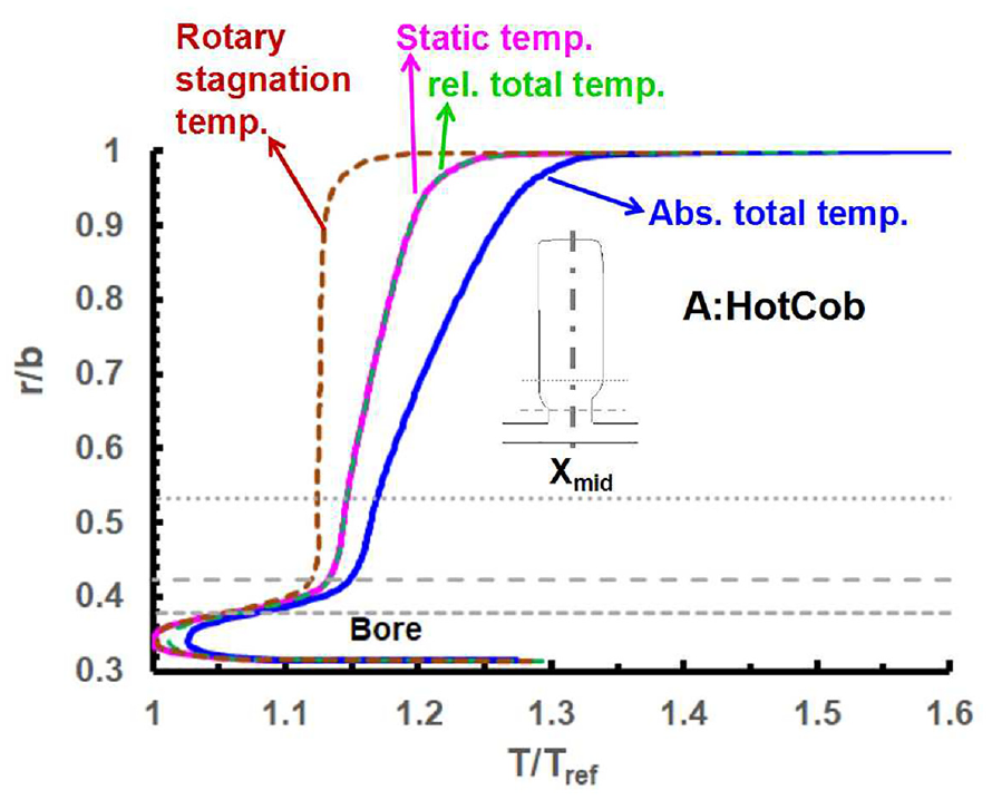
The variation of mean temperature on the mid-axial plane is shown in Figure 8 for the heated cob condition in Table 1. For this case the Eckert number is 0.31, indicating that kinetic energy effects are significant, and this is reflected in the difference between static, total, relative total and rotary stagnation temperatures. As the flow is close to solid body rotation, the relative total temperature is close to the static temperature, while the dimensional absolute total temperature is higher by approximately . The rotary stagnation temperature is exactly lower than the relative total temperature and is uniform in the main part of the cavity. All the temperatures converge at the bore where the kinetic energy associated with rotation is lower.
Mean temperature on the mid-axial plane for case A:Hotcob.
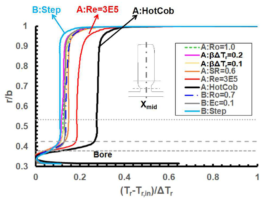
As shown in Figure 9 all the conditions studied show uniform mean rotary stagnation temperature in the cavity core. Most cases have a nondimensional core temperature of around 0.13. This value is lower than some values deduced for other cavity geometries, as discussed in section 3, and this is likely to be associated with geometrical differences that include higher nondimensional bore diameter and cob spacing for the present geometry. The stepped geometry, case B:step, has a slightly lower core temperature, consistent with impingement of the axial throughflow on the reduced diameter downstream cob encouraging flow exchange with the cavity. The core temperature rises to ∼0.28 for the heated cob condition. This is due to higher disc heat transfer that is evidently not balanced by changes in mass exchange between the cavity and the throughflow. Case A:Re = 3E5, for which is half the value for other conditions, shows a core temperature of ∼0.2. This is consistent with equation (4) which shows the strength of disc heat transfer terms increase relative to the convective term as reduces. WMLES results in Gao and Chew1 also show core temperature increasing as reduces but with less sensitivity than shown here. This may be associated with the present study being restricted to lower Reynolds numbers.
Mean temperature on the mid-axial plane for all conditions in Table 1.
Heat transfer
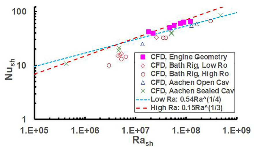
The Nusselt number based on average shroud heat transfer is plotted against rotational Rayleigh number in Figure 10. Full definitions of and are given in Nomenclature. They are based on the shroud-to-core temperature difference and the length scale of half the cavity width . For the present results fluid properties in these definitions are based on the core temperature which is taken to be the mean temperature at on the mid-axial plane in the cavity. The figure also includes results from other WMLES1,3,6,8 and correlations17 for high and low Rayleigh number convection adapted from results for free convection above a heated, horizontal flat plate. The previous WMLES simulations relate to a closed cavity configuration tested at Aachen University, an adaptation of this to include axial throughflow, and an axial throughflow configuration tested at the University of Bath. Results for the Aachen configuration generally show a trend close to as given by the high Rayleigh number correlation but with lower values than the high Rayleigh number correlation. The Bath rig simulations also show a trend close to but with slightly lower values, again. There is some sensitivity of the results to the way the heat flux is obtained numerically from the WMLES and it is considered that the three lower , ‘high Ro’, results in Gao and Chew1 may have underestimated the heat transfer. More recent results8 have used a longer sampling period to obtain the average heat flux and give high values of , as shown in the figure. For the high Rayleigh number correlation the degree of agreement between simulations and correlations is independent of the choice of as the characteristic length as this cancels from the equation for heat flux. This is not the case for the low Rayleigh number correlation . With the length scale this gives reasonable agreement with much of the WMLES data. This correlation has also been shown by Jackson et al.11 to give reasonable agreement with shroud Nusselt numbers based on measured heat transfer and estimated core temperatures for the Bath rig. However, a slightly better fit was achieved using a correlation that gives in the limit of high Rayleigh number.
Shroud heat transfer.
The present WMLES are close to the high Rayleigh number correlation in Figure 10. Differences with results for the Bath configuration may be associated with the higher number of vortex pairs and more chaotic flow observed for the present case. The selection of core temperature also differs slightly in the two studies. Other factors include a 33% higher width-to-radius ratio for the present geometry, lower inlet swirl in the Bath rig, and different surface temperature distributions with proportionally less disc heat transfer in the present case. The Aachen configuration had plane, adiabatic discs with three times that of the Bath rig and the WMLES showed four vortex pairs in the core flow. With engine shroud Rayleigh numbers extending to , use of the high Rayleigh number correlation, as adopted in section 3, is considered appropriate.
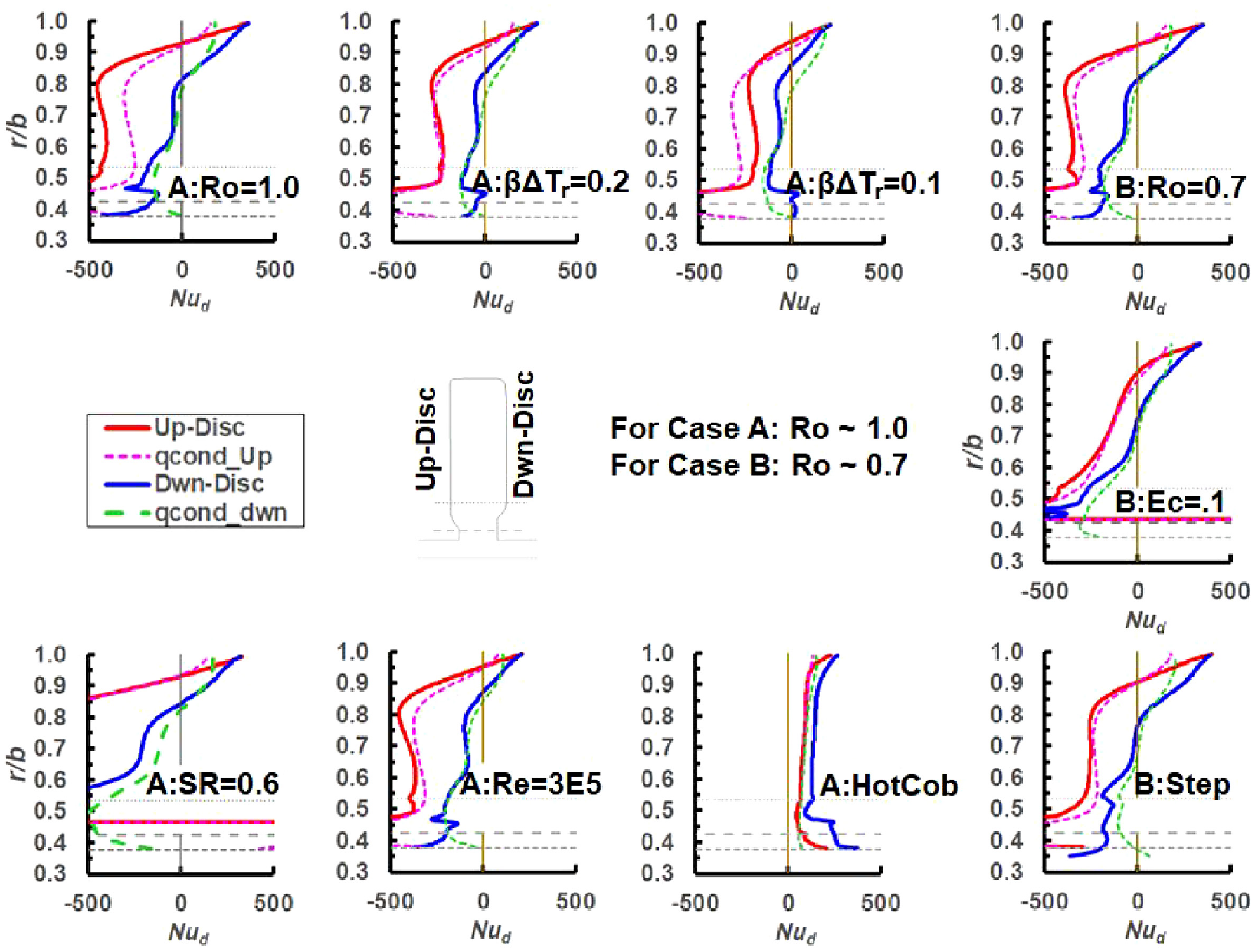
Average disc face heat transfer results are shown in Figure 11. The disc Nusselt number is based on the local radius and disc-to-inlet temperature difference . This avoids singularities that occur if the core temperature is used rather than the inlet temperature. For comparison to the WMLES results the graphs show Nusselt numbers corresponding to conduction in air between disc and core temperatures across the laminar Ekman layers of thickness . The mean core temperatures were obtained from the mid-axial plane results in Figure 9. For all cases apart from the heated cob, the disc heat flux goes to zero at or close to the point at which the disc and core temperatures are equal. At radii above this point the disc is cooled by the air, at lower radii the disc is heated by the air. As the downstream disc is hotter than the upstream disc the crossover point is at a higher radius for the upstream disc. Many of the trends in the WMLES are reflected in the Ekman layer conduction curves, although the level of agreement is variable. The WMLES generally shows higher heat transfer than the Ekman layer conduction in the corner regions at high radii.
Disc heat transfer.
Changes in disc Nusselt number for cases with varying conditions are largely consistent with the assumption of Ekman layer conduction. However, the results when , is reduced by factors 2 and 4 in cases A:=0.2 and A:=0.1 show some sensitivity. This may be associated with reduced turbulence and hence weaker axial mixing of the core flow as was discussed in Gao and Chew.1 Comparing cases A:Ro = 1 and A:Re = 3E5 changes are reasonably consistent with the Ekman layer scaling. This supports the Reynolds number scaling assumed for the elementary model in section 3. Apart from the heated cob condition, the disc temperatures approach the air inlet temperature at lower radii. As local air temperatures driving the disc heat transfer vary, this can lead to unrepresentatively large values of . Thus some of the plots have been curtailed at low . For the heated cob case the heat transfer at low disc radii is much more significant and the Nusselt number distributions are more uniform. On the upstream disc this matches the Ekman layer conduction well over most of the disc, but is higher on the downstream disc.
Cavity/throughflow mass and energy exchange
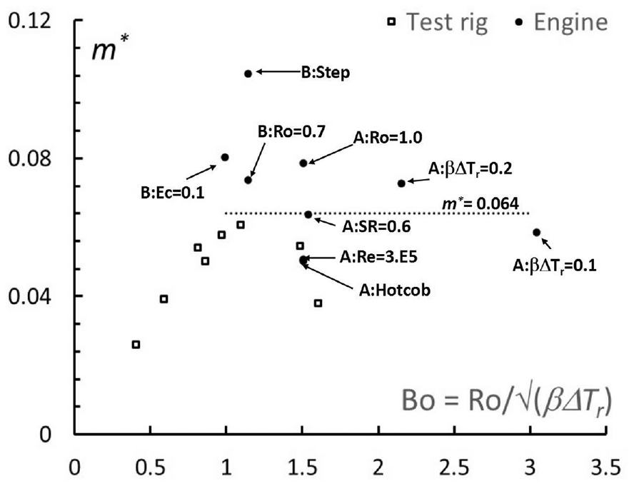
Energy gained by the cavity air through cooling of the discs and shrouds is transferred to the axial throughflow as heated air leaving the cavity is replaced by cooler air from the throughflow stream. According to the cavity energy balance given by equation (1), an exchange mass flow rate can be estimated from the cooling heat flux if it is assumed that air enters the cavity with temperature and leaves the cavity at the core temperature . Values of the nondimensional exchange flow rate obtained using the disc face and shroud heat fluxes from the WMLES are plotted against a buoyancy number in Figure 12. For comparison results from simulations of the Bath rig geometry1,8 are also shown. Considering first the present engine geometry, the stepped cob case is an outlier. The step induces the highest normalised exchange flow rate, corresponding to the lowest core temperature in Figure 9, and indicating that the exchange flow is most sensitive to this geometric change. The reduced Reynolds number and hot cob cases have the lowest normalised exchange rates corresponding to the two highest core temperatures and suggesting that changes in disc temperature affect the core temperature more than the exchange flow rate.
Energy exchange flow rates estimated from WMLES. ‘Engine’ denotes present study referring to Table 1. ‘Test rig’ results are from Gao and Chew1 and Sun et al.8
The horizontal line in Figure 12 is representative of results for the present geometry (without the stepped cob). Similar calculations for the Bath rig geometry with to 0.8 indicate lower values in most cases. The highest values of for the test rig geometry occur for . This corresponds to a peak in unsteady pressure amplitudes in Jackson et al.’s experiments.12 Differences between the test rig and engine geometry results may be explained by differences in geometry and operating conditions. The normalised cavity inlet area for the Bath rig is 57% of that for the engine geometry. The buoyancy number relates to the ratio of the forced bore flow axial velocity to the centrifugal buoyancy velocity scale. This is higher for most of the engine conditions considered than for the test rig simulations. It is of interest to note that case A:SR = 0.6 indicates a drop in as inlet swirl reduces, and that this point is relatively close to the test rig simulations in which there was no inlet swirl. Further work is required to more fully understand the factors controlling this flow exchange rate.
Comparison of WMLES with the elementary model
As described by Dixon et al.2 it is industrial practice to run finite element thermal models of engine components through a flight cycle with convective boundary conditions represented by correlations that scale the heat transfer between different operating conditions. The correlations may be adjusted to match engine temperature measurements, may be read across from previous engine models, or may be defined based on CFD predictions. For example, local disc and shroud Nusselt numbers might be calculated from a single CFD solution and then scaled to other conditions according to the buoyancy parameter and Reynolds number dependency given by the free convection and Ekman layer conduction correlations. To obtain local air temperatures a fully-mixed cavity flow could be assumed as in the elementary model of section 3, requiring further assumptions regarding the mass flow exchange or cavity air temperature. Thus it is of interest to examine to what extent the scaling implied by the elementary model reproduces that of the WMLES.
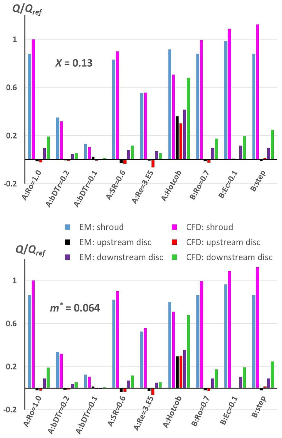
Dimensional disc and shroud heat transfer rates given by equation (2) have been calculated for conditions matching the WMLES. Two alternative assumptions regarding the core temperature are used. In one is estimated by assuming nondimensional core temperature for all cases, in the other is obtained from equation (4) with in all cases. Disc heat transfer is split into components for the upstream and downstream disc faces and the results are presented and compared to the WMLES in Figure 13. All results are normalised with respect to the WMLES shroud heat transfer for case A:Ro = 1.0.
Comparison of shroud and disc heat transfer given by the WMLES and elementary model with (top) or (bottom).
Looking first at the WMLES results, it is apparent that, apart from the case with a hot cob, shroud heat transfer is dominant. Net heat transfer from the cooler, upstream disc face is very low and most often negative. The downstream disc heat transfer is around 20% of that for the shroud. The buoyancy parameter (which incorporates the driving temperature for heat transfer) and the Reynolds number have the most effect on the level of dimensional heat transfer. The higher disc temperatures for the heated cob increase the total disc heat transfer to a similar level to that of the shroud. Introducing the stepped cob increases heat transfer on the downstream disc and, to a lesser extent, on the shroud.
The elementary model with follows the trends of the WMLES for shroud heat transfer well for most cases but cannot capture the increase in shroud heat transfer for the stepped cob or the decrease in heat transfer for the heated cob. This is consistent with experimental and WMLES studies that have indicated that core temperature only varies weakly over a range of operating conditions, but indicates other sensitivities. The disc heat transfer and its variation with operating conditions shows less agreement between the elementary model and WMLES. The level of agreement might be improved by introduction of multiplying factors in the Ekman layer conduction equation but some of the differences are due to the assumption of fixed core temperature. The disc temperatures are closer to the core temperature than the case for the shroud temperature and this gives greater sensitivity. In the elementary model the core temperature and heat transfer are independent of and . Thus the small increases in heat transfer for case B:Ec = 0.1 compared to B:Ro = 0.7 given by the model are attributed to the increase in from 0.44 to 0.47. The correspondence in trends with the WMLES for these cases confirms the effectiveness of the formulation using the rotary stagnation temperature.
The elementary model with in Figure 13 also shows reasonable agreement with WMLES shroud heat transfer for most cases. The reduced shroud heat transfer for the heated cob is now captured, but with less reduction than in the WMLES. The effect of the stepped cob is not modelled. Downstream disc heat transfer in the elementary model is consistently lower than the WMLES but trends are similar, apart from the stepped cob case. The level of agreement could be improved by introducing a constant multiplying factor for the Ekman layer conduction. This would also raise the core temperature for the heated cob case and so improve the shroud heat transfer estimate. The upstream disc heat transfer is slightly better modelled by specifying rather than . In engine flight cycle thermal modelling the disc temperature distributions typically change significantly over several minutes following very rapid engine accelerations and decelerations. Other parameters such as flow rates will adjust rapidly to the changes in pressure in the main gas path and then adjust to secondary thermal effects more slowly. Thus capture of the main effects of disc temperature on convective heat transfer modelling as other operational parameters remain constant or change slowly is important in engine applications. The present results indicate that use of equation (1) to estimate changes in core temperature while specifying the mass flow exchange is a viable approach.
Conclusions
Following recent validation of WMLES for prediction of convective heat transfer in axial compressor disc cavities against laboratory experiments, applications to an engine geometry and implications for industrial modelling have been investigated. Although direct coupling of component FE models with CFD is possible, high computing demands make this impractical. Hence use of WMLES in conjunction with more traditional modelling approaches is envisaged. This is illustrated here by comparison with an elementary model of the type used to scale heat transfer boundary conditions within transient industrial thermo-mechanical models for an engine operating cycle.
Flow and heat transfer mechanisms identified for the engine geometry are similar to those established for a research rig geometry. Differences in the number of rotating, vortex pairs observed in the buoyancy-driven, unsteady core flow may be due to geometrical differences between the rig and engine. Analysis of the mean flow confirmed existence of a constant rothalpy flow core, centrifugal Rayleigh-Bénard convection on the shroud, and Ekman layer conduction on the discs, as seen in previous studies.
Five independent, nondimensional operating parameters, , , , and , were identified as important in scaling heat transfer results within an engine operating cycle, or scaling from test or simulation conditions to engine conditions. Sensitivity to these parameters was investigated for a fixed cavity geometry and a surface temperature distribution representative of stabilised engine running condition. In addition, the effects of a change in surface temperature distribution and a reduction in bore radius of the downstream disc were simulated. An elementary model, assuming either a constant nondimensional exchange flow rate or constant nondimensional core flow temperature, reproduced the WMLES results reasonably well for the range of variation of the five parameters considered. The assumption of a constant exchange flow rate gave a better match to the WMLES for a change in temperature distribution. The introduction of a step in disc bore radius increased flow exchange between the throughflow and the cavity, and hence increased heat transfer. The elementary model, in its present form, did not capture the effects of impingement of throughflow onto the downstream disc.
It is concluded that use of WMLES can improve the accuracy and reliability of compressor thermo-mechanical modelling, reducing the reliance on engine testing and reducing risk in engine development. This is likely to be achieved through stand-alone simulations informing correlation-based thermo-mechanical models and investigating the effects of design and operating condition changes.
Footnotes
Appendix
Declaration of conflicting interests
The author(s) declared no potential conflicts of interest with respect to the research, authorship, and/or publication of this article.
Funding
The author(s) disclosed receipt of the following financial support for the research, authorship, and/or publication of this article: This research was funded from the Engineering and Physical Sciences Research Council (EPSRC) Impact Acceleration Account at the University of Surrey and from Rolls-Royce plc. It follows EPSRC grant EP/P004091 which was a joint project with the University of Bath. Support from colleagues at Rolls-Royce, the University of Surrey and the University of Bath is gratefully acknowledged.
ORCID iD
Feng Gao
References
1.
GaoFChewJW.Flow and heat transfer mechanisms in a rotating compressor cavity under centrifugal buoyancy-driven convection. ASME J Eng Gas Turbines Power2022; 144(5): 051010.
2.
DixonJAVerdicchioJABenitoD, et al. Recent developments in gas turbine component temperature prediction methods, using computational fluid dynamics and optimization tools, in conjunction with more conventional finite element analysis techniques. Proc IMechE, Part A: J Power and Energy2004; 218(4): 241–155.
3.
GaoFPitzDBChewJW.Numerical investigation of buoyancy-induced flow in a sealed rapidly rotating disc cavity. Int J Heat Mass Transf2020; 147: 118860.
4.
SainiDSandbergRD.Simulations of compressibility effects in centrifugal buoyancy-induced flow in a closed rotating cavity. Int J Heat Fluid Flow2020; 85: 108656.
GaoFChewJW.Ekman layer scrubbing and shroud heat transfer in centrifugal buoyancy-driven convection. ASME J Eng Gas Turbines Power2021; 143(7): 071010.
7.
SainiDSandbergRD.Large-eddy simulations of high Rossby number flow in the high-pressure compressor inter-disk cavity. ASME J Turbomach2021; 143(11): 111002.
8.
SunZGaoFChewJW, et al. Large eddy simulation investigation of low Rossby number buoyant flow in rotating cavities. ASME J Eng Gas Turbines Power2022; 144(12): 121023.
9.
LubertiDPatiniosMJacksonRW, et al. Design and testing of a rig to investigate buoyancy-induced heat transfer in aero-engine compressor rotors. ASME J Eng Gas Turbines Power2021; 143(4): 041030.
10.
JacksonRWLubertiDTangH, et al. Measurement and analysis of buoyancy-induced heat transfer in aero-engine compressor rotors. ASME J Eng Gas Turbines Power2021; 143(6): 061004.
11.
JacksonRWTangHScobieJA, et al. Analysis of shroud and disk heat transfer in aero-engine compressor rotors. ASME J Eng Gas Turbines Power2021; 143(9): 091005.
12.
JacksonRWTangHScobieJA, et al. Unsteady pressure measurements in a heated rotating cavity. ASME J Eng Gas Turbines Power2022; 144(4): 041017.
13.
LongCAChildsPRN. Shroud heat transfer measurements inside a heated multiple rotating cavity with axial throughflow. Int J Heat Fluid Flow2007; 28: 1405–1417.
14.
GaoFChewJW.Evaluation and application of advanced CFD models for rotating disc flows. Proc IMechE, Part C: J Mechanical Engineering Science2021; 235(23): 6847–6864.
15.
LongCATuckerPG.Shroud heat transfer measurements from a rotating cavity with an axial throughflow of air. ASME J Turbomach1994; 116(3): 525–534.
16.
AmiranteDHillsNJ.Large-eddy simulations of wall bounded turbulent flows using unstructured linear reconstruction techniques. ASME J Turbomach2015; 137(5): 051006.
17.
LloydJRMoranWR.Natural convection adjacent to horizontal surface of various planforms. ASME J Heat Transf1974; 96(4): 443–447.