
Abstract
This study investigates the friction stir welding properties and resulting microstructural and mechanical properties of XPF800 steel, which is commonly used in automotive chassis and suspension components. The welding parameters were optimized with a tungsten carbide (WC) tool at a downforce of 11 kN, traverse speed of 95 mm/min, and rotating speed of 750 rpm. Microstructural analysis was conducted using scanning electron microscopy (SEM), optical microscopy (OM), and Energy Dispersive X-ray Spectrometry (EDS). Mechanical properties were evaluated through tensile, Charpy impact, and microhardness tests. Results showed that acicular ferrite formed in the stir zone, contributing to an increase in strength, with a maximum hardness of approximately 350 HV0.1. However, the heat affected zone (HAZ) experienced softening, resulting in a decrease in both tensile strength and hardness by approximately 8% and 20%, respectively, compared to the base material.
Introduction
AHSS and HSLA steels, which were developed based on the requirement for an increase in strength, are frequently preferred in the automotive industry.1,2 However, hard phases such as martensite and bainite in the microstructure of these steels, which enhance their strength, significantly reduce their formability.3,4 Low carbon steels are of high strength and good formability.5,6 TATA steel has developed a new micro-alloyed ferritic hot rolled steel with the commercial name of XPF for use in automotive chassis and suspension elements. XPF800 comprises single-phase ferrite but lacks of containing complex phases, which is why it has the characteristics of high strength and good formability. XPF800 steel owes its high strength to the precipitation hardening and grain refinement mechanisms of microalloying elements.7–9 Rijkenberg et al. 9 indicated that hole expansion capacity (HEC), that is, indicator of formability, of XPF steels are superior to high strength low alloy (HSLA) and dual-phase (DP) steels. Koley et al. 10 clarified that high HEC value is of great importance for deep drawing applications in the automotive industry.
HAZ softening in the welding of low carbon steels affects the quality of the weld due to the decreasing strength. A decrease in hardness and strength was observed due to HAZ softening in the fusion welding of low carbon XPF steels.7,8 The microstructure in the HAZ of which temperature was above Ac1 during welding consists of austenite and proeutectoid ferrite. When the temperature reached below Ar1, austenites transformed into ferrite and pearlite, and the proeutectoid ferrite grains became coarser. The gradual coarsening of the fine-grained ferrite from the base metal to HAZ and the increase in the ferrite ratio in the microstructure is considered to be the reasons for HAZ softening.11,12
Russo Spena et al. declared that the identification of suitable welding techniques for the parts to be joined in the automotive industry is crucial for the microstructure alterations that take place during welding. 13 Dong et al. 14 reported that the cooling rates and welding heat input during GTAW are the most critical parameters affecting the microstructure. Korkmaz and Meran 8 clarified that the relationship between the heat input and cooling rates of low-carbon steels such as XPF800 brings about the formation of different ferritic microstructures. Singh et al. 15 indicated that high heat inputs while arc welding lead to a decrease in the cooling rate and the growth of grains. Cui et al. 16 demonstrated that cooling rates increase at low heat inputs during K-TIG. De et al. 17 reported that the cooling rates during FSW of mild steel are lower compared to those of fusion welding. FSW has lower heat input, distortions, residual stress, and smaller heat affected zone (HAZ) compared to conventional arc welding methods. Hence, excellent mechanical properties are obtained. FSW is a solid-state joining techniques. 18 The tool is one of the parameters mandatory for proper FSW. The tool to be used must comprise a non-consumable pin and shoulder. The shoulder of the rotating tool is plunged into the workpiece until it touches the surface of the workpiece. The heat required for softening the material is generated by the friction between the workpiece and the tool. With the combination of rotation and travel of the tool, the plasticized material moves from the front to the back of the tool and the material undergoes plastic deformation. 19 Although developed originally for low melting Al-alloys in order to avoid defects such as porosity formation, 20 FSW has also the potential to be used in the joining of steels. 21 Notably, the factors such as large distortions, coarse dendritic structures, segregation, and high energy consumption in arc welding pave the way for the use of the FSW method for the joining of steels in the automotive industry.18,22–24 FSW started to be applied primarily to aluminum (Al) and its alloys. Later, it was used for joining similar or somewhat higher melting temperature materials such as magnesium (Mg) and its alloys as well as copper (Cu) and its alloys.25,26 In the literature, there are plenty of studies investigating the microstructure and mechanical properties of steels such as low carbon steel 27 mild steel, 28 high carbon steel, 29 low alloy medium carbon steel, 30 etc. Lakshminarayanan et al. 31 investigated the properties of FSW of steel plates at the parameters of the rotational speed and the traverse speed of 800 rpm and 50 mm/min, respectively. Matsushita et al. studied the mechanical and microstructural properties of FSW of AHSS carried out with WC based tool at 200–600 rpm rotational speeds and 10–60 mm/min traverse speeds. Besides, they observed a decrease in strength due to the softening in TMAZ and HAZ. 32
Disclosing the welding properties of XPF800 steel exposed to different welding methods will enable them to be used more effectively in the automotive industry. In the authors’ previous studies, the microstructure and mechanical properties of XPF800 plates joined by GTAW and GMAW methods, which are fusion welding methods, were examined.7,8 There are no studies in the literature on the FSW of XPF800 steel. Therefore, the effect of friction stir welding on the mechanical and microstructural properties of XPF800 steel was investigated in this study.
Experimental
Welding details
Micro-alloyed hot rolled XPF800 steel plates of which chemical composition which is Fe-0.05C-1.7Mn-0.1Si-0.001P-0.005S-0.001Al-0.1Ti-0.06Nb-0.2V-0.15Mo (wt.%) was studied. The plates were cut utilizing a water jet in the dimensions of 3 mm × 100 mm × 200 mm. The study employed a tungsten carbide (WC) tool due to its exceptional resistance to high temperature and wear during FSW. The utilization of conical tip tools, as opposed to flat cylindrical tip tools, was found to be advantageous in promoting a more uniform material flow during FSW, while also reducing the required downforce. This is attributed to the ability of conical tip tools to induce a more homogeneous deformation in the workpiece material. To achieve a smoother weld surface, it is recommended that the tool’s shoulder diameter be approximately three times the diameter of the pin.33,34 A tungsten carbide (WC) tool, the geometric dimensions of which are given in Figure 2, was used during welding. The FSW tool has a diameter shoulder of 18 mm. The conical pin diameter and length of the tool are 5 and 2.5 mm, respectively. Preliminary experiments were conducted to determine the parameters according to which FSW will be carried out. The parameters of the FSW tool, that is, rotating speeds, traversing speeds, and downforces, used during the preliminary experiments were determined to be 600/750/950/1180 rpm, 60/75/95/118 mm/min, and 9/11/12/14 kN, respectively. The tilt angle of the tool was maintained at a fixed angle of 0°. For FSW to be accomplished effectively, the surrounding material of the tool must achieve a suitable softening temperature and display plastic flow. It has been observed that the attainment of full penetration could not be achieved due to the inability to reach a sufficiently high temperature under low rotating speed and high traverse speed conditions. Furthermore, it was noted that the pin of the tool used made contact with the lower plate that held the welding plates, leading to significant deformation and fracture under high downforces. Based on the macro and tensile test analyses, the best results were obtained at rotating speed of 750 rpm, traverse speed of 95 mm/min, and downforce of 11 kN.
Microstructure examinations
K-type thermocouples were used to calculate the peak temperature in stir zone (SZ). Thermocouples were placed just beneath the center of the pin at 40 mm intervals to determine the temperature of the SZ. Besides, the highest temperature at the welded surface was monitored with Testo 845 infrared thermometer with an accuracy of ±2.5°C, and within the temperature range from 100°C to 950°C. The emissivity of the infrared thermometer was set to 0.95. 1 The schematic representation of the thermocouples, infrared thermometer, and WC tool is represented in Figure 1(a), and the geometric details of the WC tool are demonstrated in Figure 1(b).
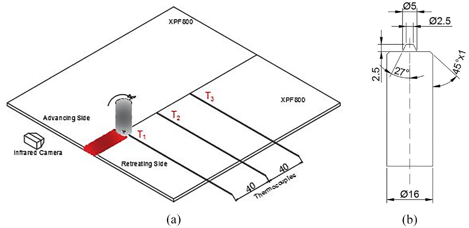
Schematic illustration of: (a) FSW of XPF800 steel and (b) tool dimensions (all dimensions are in mm).
The geometric dimensions of the test samples are presented in Figure 2(a). The surfaces of the samples were prepared with the aid of well-known conventional grinding and polishing techniques and subsequently etched in Nital solution (2% HNO3) for 30 s for metallographic examination purposes. After FSW, there are four different regions: stirred zone (SZ), thermomechanically affected zone (TMAZ), heat affected zone (HAZ), and unaffected base material (BM). SEM and OM were used for the microstructure analysis of these regions. In addition, EDS (Energy Dispersive X-ray Spectrometry) were used to determine the atomic concentrations of the elements in the SZ. Zeiss Supra 40 VP device was used for SEM and EDS.
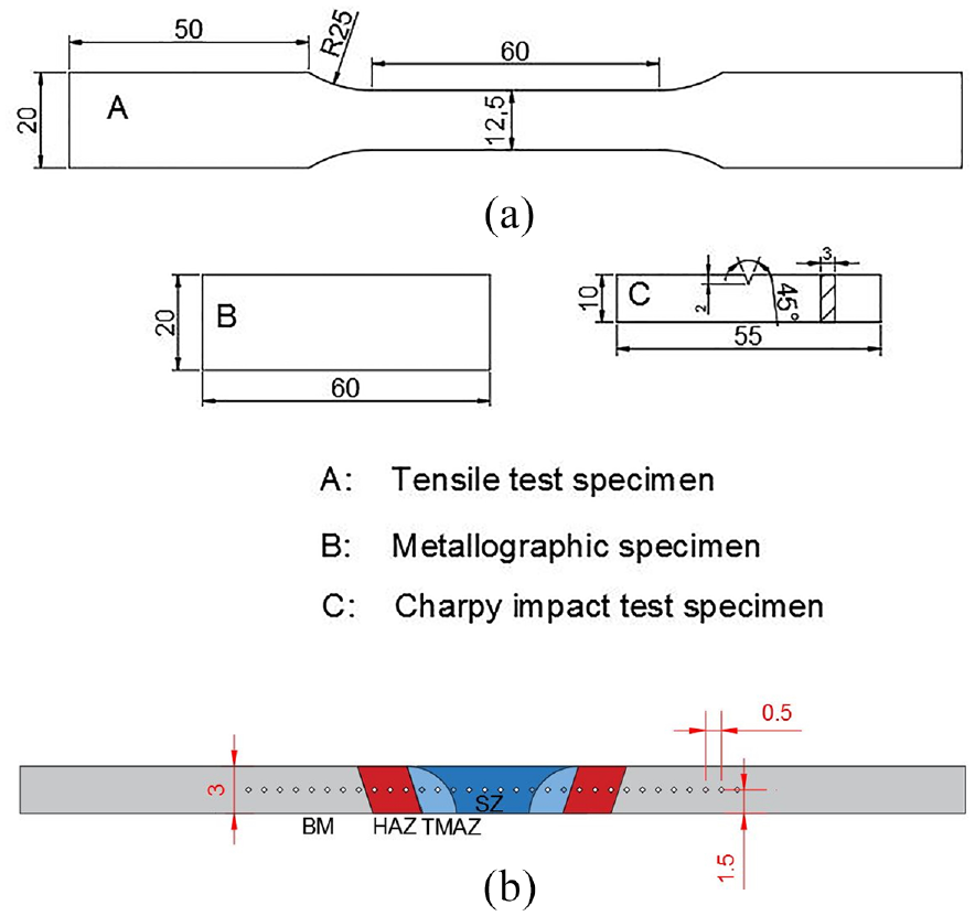
Test specimens’: (a) dimensions and (b) points of microhardness measurement (all dimensions are in mm).
Mechanical properties
Vickers microhardness, Charpy impact, and tensile tests were used to specify the mechanical properties of welded XPF800. The test specimens were set up based on ASTM E8 standards. A universal machine was employed for the tensile tests with a crosshead speed of 1 mm/min. The fracture analysis of both BM and FSWed samples was carried out based on high resolutions images which are taken from SEM. Vickers microhardness test device is used with a 100 g load for 10 s to measure the microhardness of SZ, TMAZ, HAZ, and BM. Vickers microhardness was measured at 0.5 mm intervals (Figure 2(b)).
Results and discussion
Microstructure
The microstructure of the XPF800 steel before friction stir welding was applied is shown in Figure 3. While precipitations are random in XPF650 interphase precipitations are frequently observed in XPF1000. 9 Figure 3 shows that the precipitation was randomly distributed, and a fine-grained ferritic microstructure was monitored. The average grain size of ferrite was measured at approximately 3.4 µm.
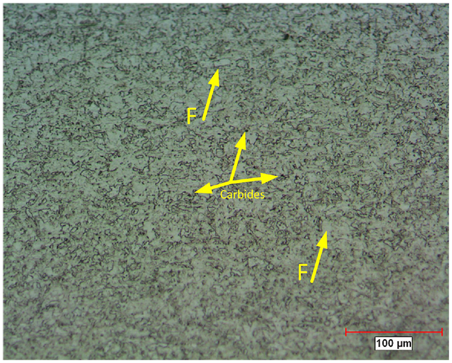
Optical micrograph showing the microstructure of XPF800 base material.
The images of the plates after FSW and the WC tool used before and after FSW are shown in Figure 4. It is seen that the WC tool was slightly deformed during FSW. For this reason, the tool was used once during each welding. It will be critical to use a tool with higher abrasion resistance during FSW so that the tool can be reused.
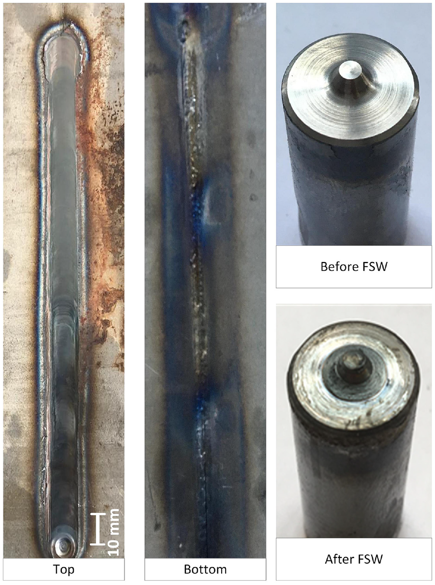
Images of friction stir welded plate and tool.
The A1 and A3 temperatures, which were around 650°C and 830°C respectively, were determined based on the chemical composition of the XPF800 base material and a temperature and phase ratio graph constructed using JMatPro software. Figures 5(b) and 6(a) show respectively OM and SEM images of the microstructure of the advancing side (AS) of the stir zone (SZ). As the temperature and deformation rates on both advancing and retracting sides are highly comparable, TMAZ display nearly identical microstructures. Therefore, only images of the advancing side are presented in this study. FSW is a thermomechanical process that causes severe plastic deformation. Severe plastic deformation is seen in SZ due to friction and heat. Therefore, dynamic recrystallization (DRX) is sighted in SZ during FSW. There are two different types of DRX mechanism, discontinuous DRX (DDRX), and continuous DRX (CDRX). 35 Fine and equiaxed grains are formed as a result of DRX. 36 In addition, a deformation-induced ferrite transformation (DIFT) mechanism takes place, resulting in an increase in the number of ferrite grains per unit area due to high plastic deformation near A3 temperatures and thereby causing grain refinement. 1 The microstructure of SZ was composed of polygonal ferrite, acicular ferrite, and perlite (Figure 5(b)). During the FSW, temperatures in the SZ were measured at about 864°C. Acicular ferrite is generated by nucleation from inclusions during cooling from high temperatures. In the absence of inclusions in the microstructure, the formation of bainitic ferrite is observed instead of acicular ferrite. 37 The presence of acicular ferrite enhances the impact toughness by hindering the propagation of microcracks and also contributes to increased hardness.7,8 It is thought that the temperatures in SZ during FSW rise above A3, and the ferrite completely transforms into austenite. The austenite turned into pearlite during cooling. Acicular ferrite was observed in SZ as well. However, acicular ferrite was not observed uniformly across the SZ, and was found to be partially formed in certain regions only. Additionally, during cooling, proeutectoid ferrite was shaped at the former austenite grain boundaries and transformed into polygonal ferrite. Generally, the microstructure of SZ in low carbon steels after FSW consists of fine ferrite and pearlite. However, at medium and high carbon steels, not only ferrite, perlite but also martensite, and bainite may occur in the microstructure of the SZ depending on the carbon ratios and the highest temperatures reached. 36
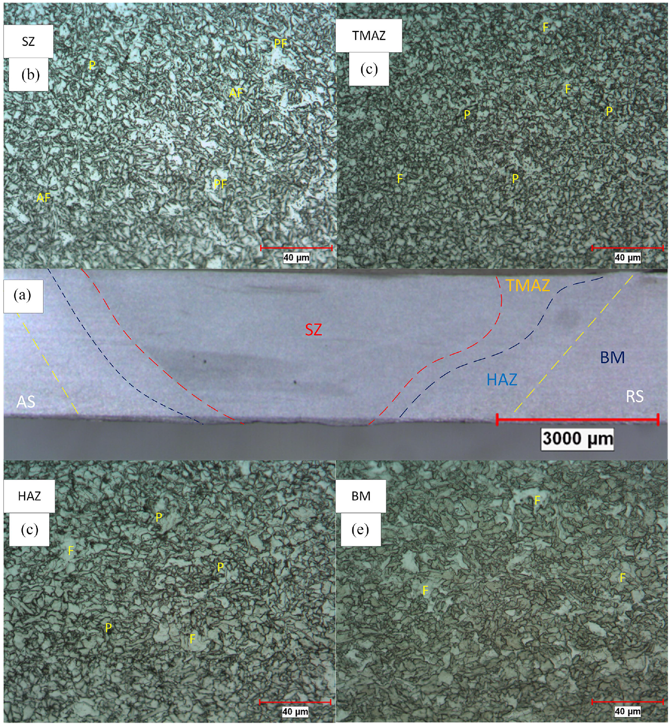
OM images of friction stir welded XPF800 steel samples: (a) a cross-sectional view of the FSW-exposed XPF800 steel sample, with regions of advancing side schematically indicated, (b) stir zone (SZ), (c) thermomechanically affected zone (TMAZ), (d) heat-affected zone (HAZ), and (e) base material (BM). F: ferrite; P: pearlite; AF: acicular ferrite; PF: polygonal ferrite.
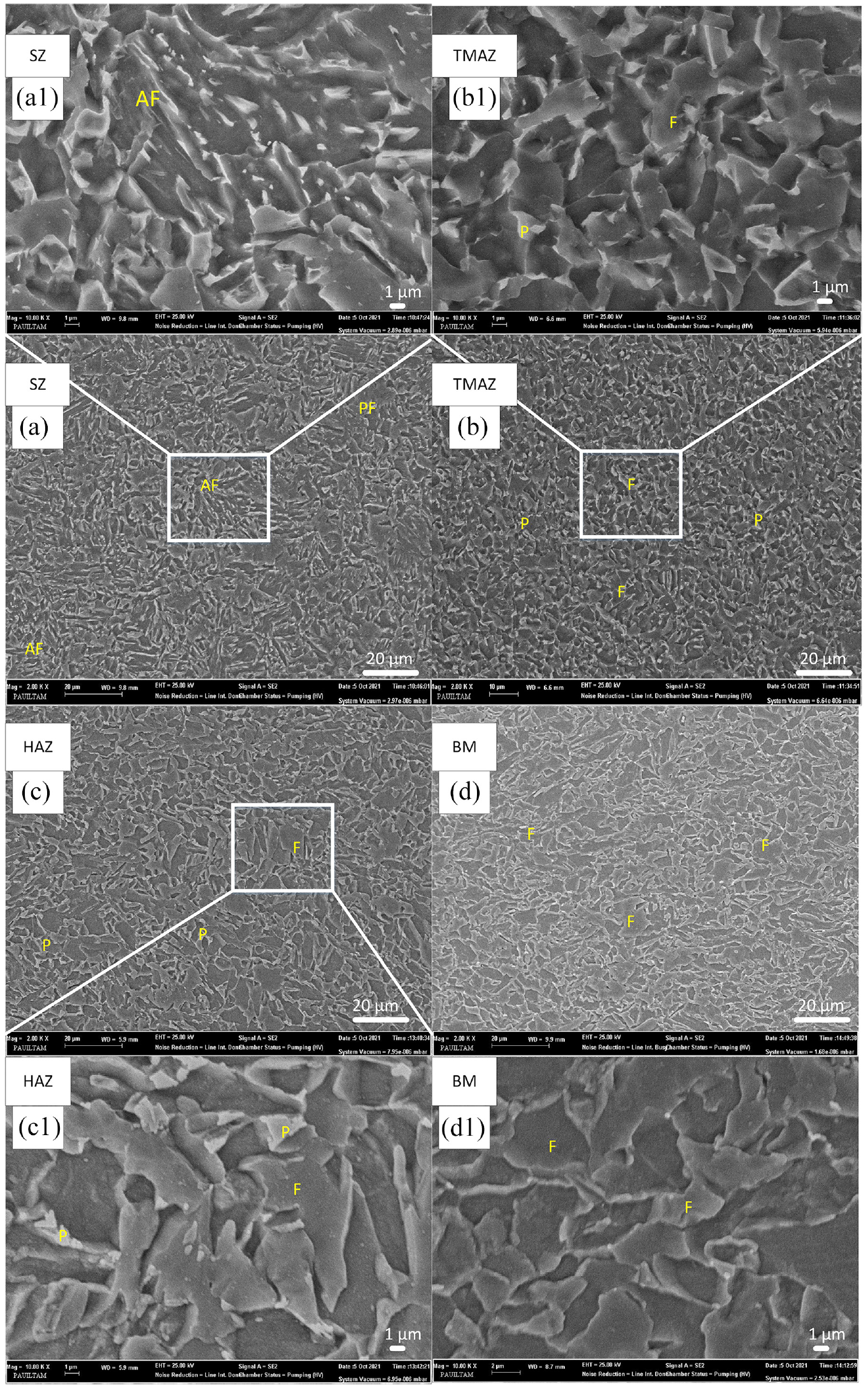
SEM images showing microstructures of the advancing side of the friction stir welded zone: (a-a1) SZ, (b-b1) TMAZ, (c-c1) HAZ, and (d-d1) BM of the advancing side. F: ferrite; P: perlite; AF: acicular ferrite; PF: polygonal ferrite.
In low carbon steels, the temperature rising above A3 during FSW causes the formation of single-phase austenite in the microstructure. After recrystallization, coarse grains may form in the SZ due to the absence of secondary phases to prevent grain coarsening due to high temperatures. Liu et al. clarified that if the temperatures remain between A1 and A3, α + γ dual phase regions are formed, and recrystallized α and γ act as secondary phases to each other, causing a decrease in grain coarsening. 38 A fine-grained microstructure was observed in the SZ as a result of excessive plastic deformation and recrystallization. However, when compared to TMAZ, the grains were slightly larger in SZ. The average ferrite grain size in the SZ was found to be approximately 2.8 µm, whereas in the TMAZ, it was measured to be around 2.6 µm. The reason for this is thought to be due to the fact that the temperatures in the SZ are above the A3 temperature and the absence of secondary phases to prevent the coarsening of the grains.
OM and SEM images of the advancing side (AS) microstructure of the TMAZ are given in Figures 5(c) and 6(b)–(b1), respectively. The microstructure of TMAZ consisted of ferrite and perlite. This microstructure indicated that the temperatures are between A1 and A3 during FSW. The proeutectoid ferrite and austenite formed above the A1 temperature in TMAZ. During cooling the proeutectoid ferrite remained the same and austenite turned into pearlite. Acicular ferrite was not seen in TMAZ since the temperature of A3 was not exceeded during FSW. Wang et al. proposed that AF nucleates intragranularly around inclusions consisting of O, Si, Ti, Al, etc. 39 It is thought that, although the grains may have elongated due to plastic deformation during FSW, the grains that undergo dynamic recrystallization during cooling become fine and equiaxed grains. 36
Figures 5(d) and 6(c)–(c1) show the images of the OM and SEM of the advancing side microstructure of HAZ, respectively. During the FSW, the microstructure of the HAZ is seen to be composed of ferrite and a small number of pearlite. It reveals that some of the ferrite grains are fine and equiaxed, while some ferrite grains are composed of coarse grains. For this reason, it can be said that the HAZ reaches a temperature just above the A1, and the few austenite grains turn into pearlite and fine-grained ferrite, while the unconverted ferrite grains become larger with increasing temperatures. The average ferrite grain size in HAZ was measured as approximately 4.8 µm. In addition, the HAZ is only affected by temperature, rather than the plastic deformation of the tool. Therefore, the lack of recrystallization in this region resulted in the formation of a coarse grained structure. As XPF800 steel is a hot-formed steel, the increase in strength induced by dislocations is relatively low. High strength is achieved through precipitation hardening and grain refinement mechanisms. Although recrystallization occurs in the SZ and TMAZ, an increase in dislocation density due to excessive plastic deformation can be observed. It is hypothesized that the dislocation density does not increase in the HAZ, where plastic deformation does not occur. OM and SEM images of the microstructure of the AS of the BM are given in Figures 5(e) and 6(d), respectively. It is thought that the temperatures of the BM region during FSW remain below the A1. Therefore, no phase transformation is expected. When the OM and SEM images are analyzed, it is seen that the microstructure of the BM consists of equiaxed and fine-grained ferrites. In addition, it is seen that the carbides are both randomly and homogeneously distributed in the microstructure.
EDS analysis results of the FSWed sample are given in Figure 7(a). When the results of the EDS analysis are examined, the presence of oxides to support acicular ferrite formation in the SZ is observed. Wan et al. declared that AF nucleates intragranular around inclusions consisting of O, Si, Ti, Al, etc. 40 This information confirms the formation of acicular ferrite in SZ. Additionally, Wolfram (W) element was found in the EDS analysis performed on a point in Figure 7(a1). This proves the existence of parts broken off from the WC-based tool during FSW. The wolfram element in the SZ is thought to form WxC intermetallic brittle phases.
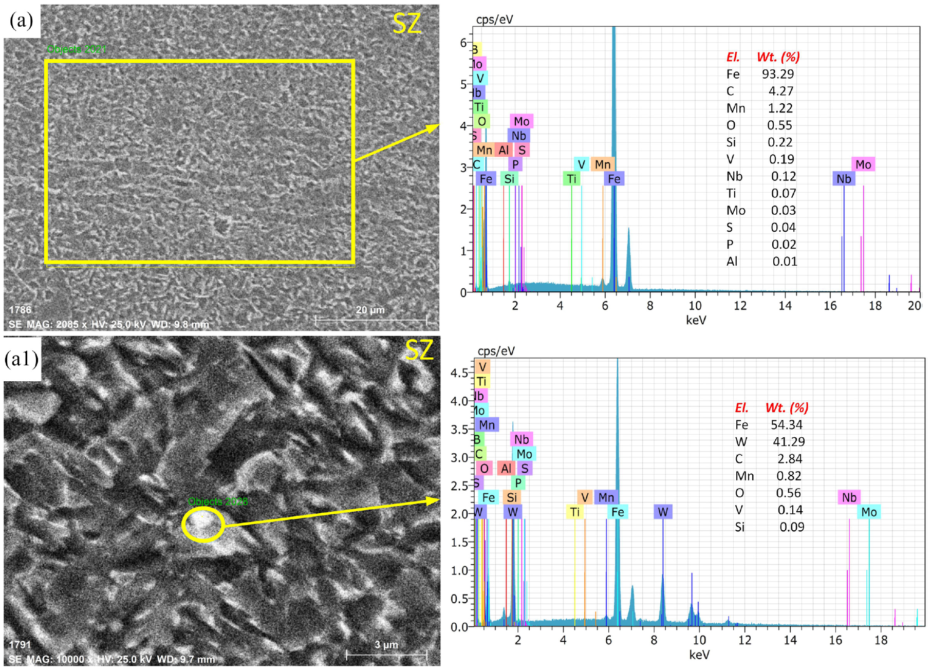
Energy dispersive X-ray spectrometry results of: (a-a1) SZ.
Microhardness analysis
Vickers microhardness values are given in Figure 8. The hardness of SZ, which has acicular ferrite in its microstructure and undergoes extreme plastic deformation, was measured as approximately 350 HV0.1. The BM hardness after FSW was measured as approximately 300 HV0.1. When the hardness between SZ and BM are compared, it is seen that the microhardness value of SZ is approximately 16% higher than that of BM. Ma reported that the intermetallic phases also contribute to the hardness. 19 Therefore, it can be concluded that the intermetallic phases contribute to the increase in hardness in the SZ. When the microhardness of TMAZ after FSW were examined, it was measured as about 340 HV0.1 on the advancing side (AS), and 325 HV0.1 on the retreating side (RS). The difference between the hardness values on these two sides is thought to be due to the fine-grained microstructure and high dislocation density formed by the effect of excessive plastic deformation on the advancing side. 41 Although there is a finer-grained structure in TMAZ, it can be said that acicular ferrite formed in SZ contributes to the increase in hardness. TMAZ undergoes less plastic deformation than SZ. The softening observed in the HAZ is considered to be caused by the presence of coarse-grained ferrite in the microstructure and an increase in the ferrite ratio, which is a soft phase. The AS and RS of HAZ compared to other regions, the hardness was measured as approximately 280 HV0.1. HAZ hardness decreases approximately 20% compared to that of BM. It can be said that this region undergoes HAZ softening.
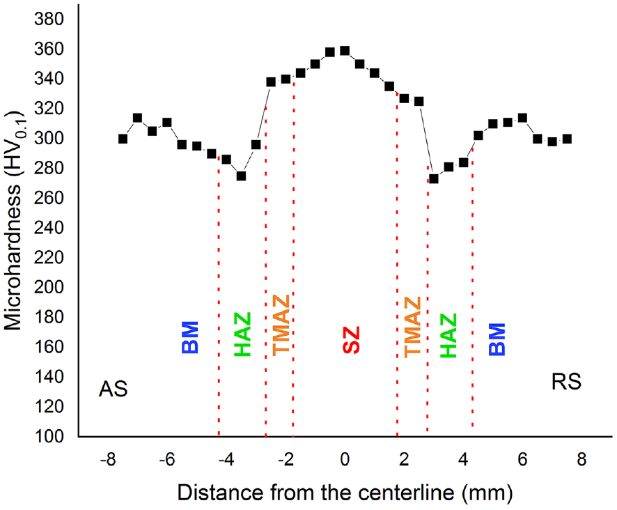
Vickers microhardness distribution.
Tensile properties
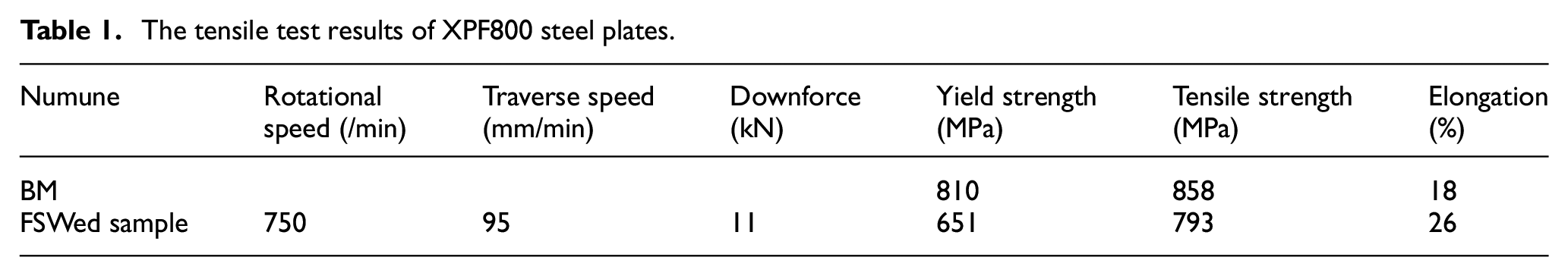
The tensile test results of the base material and FSWed sample are summarized in Table 1. The tensile and yield strength values of the base material were approximately 858 and 810 MPa, respectively. After FSW, the tensile and yield strength decreased by about 8% and 19% and were obtained as 793 and 651 MPa. These strength decreases are due to the HAZ softening. The coarsening of the grain size in HAZ is reason for the strength reduction. The failure has been observed to occurred in AS of HAZ as seen in Figure 9. The total elongation of BM and welded samples is 18% and 26%, respectively. The elongation of the FSWed sample showed an increase of approximately 42% according to that of BM.
The tensile test results of XPF800 steel plates.
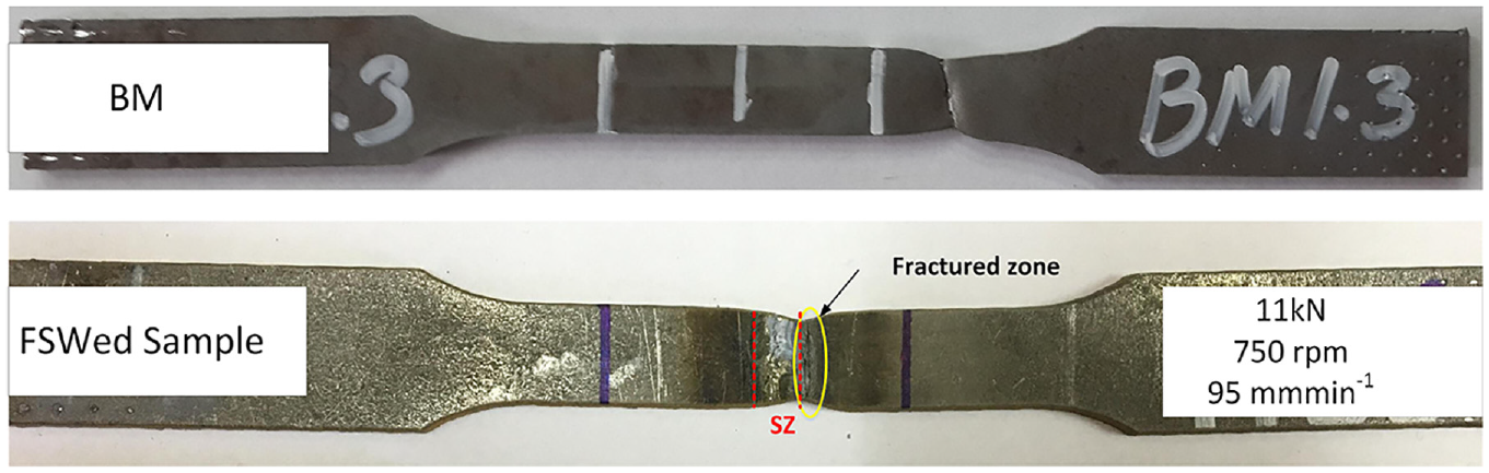
After tensile test images of XPF800 base material and friction stir welded sample.
Impact toughness
While the base materials’ impact energy was 46 J on average, that of welded sample was found to be 40 J on average. AF increases the toughness due to the resistance against the fracture. However, the presence of a small number of acicular ferrites in the microstructure did not contribute to the increase in the toughness. In the literature, there is information related to acicular ferrite which makes the impact toughness increase by avoiding the microcracks’ spread.7,8,14,39,42 SEM was used to analyze the fracture surfaces. In both samples, ductile fracture was observed. Figure 10(a) depicts that dimples and river-like patterns (characteristic of ductile-like fracture) are formed on the fracture surfaces of the BM. Similarly, many dimples are seen on the surface of welded specimens, which shows ductile fracture (Figure 10(b)).
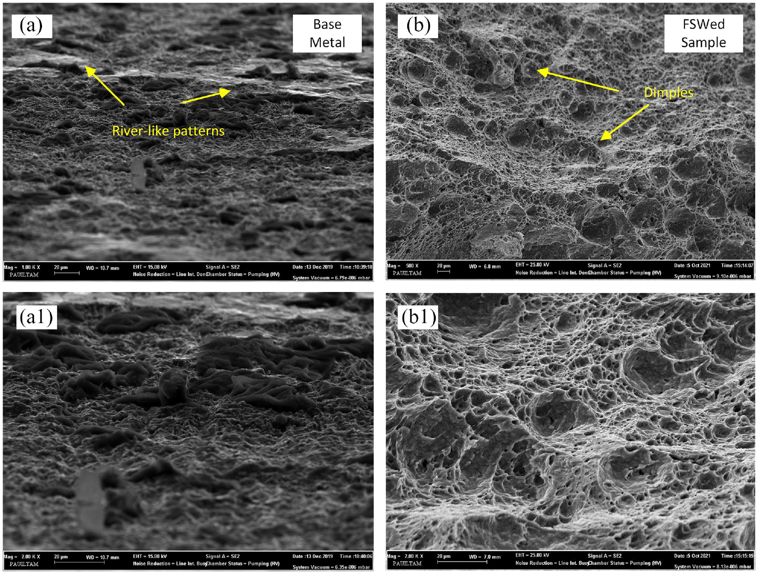
Surface of fracture of: (a-a1) XPF800 base material and (b-b1) friction stir welded sample.
Conclusion
In this study, FSW was successfully performed on XPF800 steel using a WC tool with the parameters of a downforce of 11 kN, a traverse speed of 95 mm/min, and a rotating speed of 750 rpm.
The important results are summarized below:
The microstructure of SZ with dynamic recrystallization in friction stir welding is mainly composed of polygonal ferrite, acicular ferrite, and pearlite. The microstructure of TMAZ, which is exposed to plastic deformation, is composed of ferrite and pearlite. While ferrite and pearlite are formed in the microstructure of HAZ, it contains fine-grained equiaxed ferrites in the microstructure of the BM.
The presence of oxides was observed in the EDS analysis of SZ after friction stir welding and AF formation was observed in certain regions when microstructure images were examined.
Acicular ferrites grow by nucleating in inclusions, and increase toughness, hardness, and strength. The hardness was measured to be the highest in SZ due to both fine grains and AF formation. However, the fact that AF shows up only in some regions of the microstructure is thought to contribute partially to the increase in toughness.
Tensile strength and microhardness of the welded sample decreased compared to base material due to HAZ softening after FSW.
Footnotes
Acknowledgements
We kindly thank to SIO Automotive Inc©., Tekirdağ, Turkey for supplying the XPF800 steel sheets.
Declaration of conflicting interests
The author(s) declared no potential conflicts of interest with respect to the research, authorship, and/or publication of this article.
Funding
The author(s) disclosed receipt of the following financial support for the research, authorship, and/or publication of this article: This works was supported by Scientific Research Projects of Pamukkale University, under Grant No: 2020FBE033.