
Abstract
The effective operation of water management systems is contingent upon leak localization and detection – a common problem that is more acute in large networks. This paper reviews the salient literature in this context and demonstrates the effectiveness of leakage location methods (LLMs) and leakage detection methods (LDMs). Although there is a significant amount of literature that discusses leakage localization and detection technologies, an academic lacuna still exists concerning the linkage between degradation mechanisms and LDMs and do not cover or connect past efforts from the start of a degradation mechanism that leads to changes in the mechanical strength (such as a reduction in fracture toughness) of pipes and results in crack propagation and leakage. This review focuses on these issues in the context of degradation mechanisms and common detection methods.
Introduction
Underground pipe networks can be found all over the world. However, significant challenges persist. For example, metal pipes are prone to corrosion, which has a negative impact on networks. In addition to the increased costs to service providers and reduced network longevity, customers also experience a negative impact. This underlines why research at the micro and macro levels needs to be undertaken to enhance pipeline integrity. 1 According to Nykyforchyn et al. 2 ruptures occurring in steel pipes are typically caused by stress cracking. Moreover, there are significant impacts upon steel pipe properties over extended periods of time and usage, 3 resulting in reduced plasticity, strength, toughness, and fracture resistance and increased fatigue, resulting in crack propagation. 2 Elements such as hydrogen have a significant impact on pipe networks because they accelerate fracture mechanisms. 3 This means that quantifying and understanding the deterioration of pipes is imperative for pipe network design, implementation, and maintenance. Figure 1 below provides examples of types of corrosion in metal pipelines, which is typically classed as the primary cause of metal pipe degradation. Degradation can be defined as being the loss of metal that occurs on the interior and exterior surfaces of a pipe.
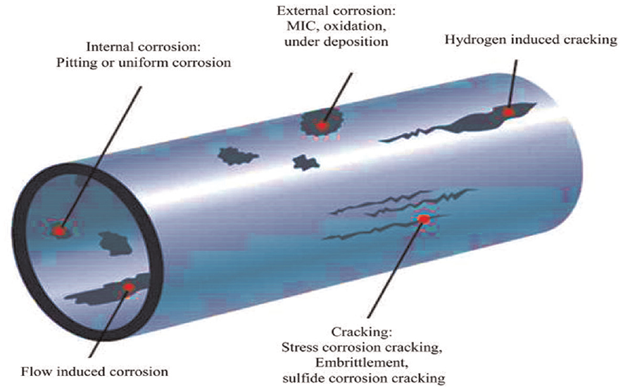
Types of corrosion in metal pipelines. 4
The impact of pipe corrosion is a common theme researched over the previous decades. Proponents such as Yamamoto et al. 5 analyzed residual strength from corroded cast iron pipes and conducted tests that involved measuring corrosion based on the percentile graphitization area over a pipe cross-section. Other researchers undertook tests on corroded pipes that were approximately 100 years old and concluded that corrosion had reduced pipe strength. 6 Tensile strength tests carried out on corroded pipes by other researchers found that there was a link between residual tensile strength and the average pit depth of a pipe wall thickness. 7 On the other hand, proponents such as Benjamin et al. 8 concluded that the loss of mass caused by corrosion is linked to the loss of strength of the steel and results in leakage. Identifying the relationship between these parameters and the processes associated with degradation is important when attempting to comprehend the evolution of leakage detection.
Some of the literature8,9 indicates that the testing of steel pipe sections with artificial corrosion defects is common. It should be noted that the failure mechanisms associated with artificial defects, such as blunt and flat-bottomed defects, differ from those that occur naturally. 10 Cracks can be initiated by corrosion-induced pitting, especially in cast iron, because a natural corrosion-induced pit typically has a rough surface. 6 Clark et al. 11 categorized pipe leakage into circumferential, longitudinal, and split bell breakages, which are caused by longitudinal stresses, transverse stresses (hoop stress) and transverse stresses on the pipe joint, respectively. Soil moisture content and pH values can also have negative repercussions for pipe properties. For example, by reducing fracture toughness, which will eventually lead to catastrophic failure in cast iron pipes. 12
Nykyforchyn et al. 2 and Zagórski et al. 13 found that crack propagation significantly reduced resistance to corrosion fatigue and hydrogen-induced cracking, which are common features of the failure mode for steel pipes used for carrying natural gas, especially in wet environments. Recently, the literature has focused more on the concept of mechanical stability when discussing steel material degradation. Shyyan, for example, assessed how the level of residual mechanical stability and embrittlement could significantly reduce structural plasticity. A reduction in steel plasticity is typically associated with characteristics such as corrosion and the brittle nature of the material. However, these characteristics are significantly more noticeable. Hence, an assessment based on plasticity features, such as those presented in tensile strain diagrams, can be inaccurate in their prediction of the long-term operation of steel pipes. 14
Pipe degradation is representative of typical external damage to both cast and ductile iron pipelines. In the case of gray cast iron pipelines, this damage may be obscured because of “graphitization,” which refers to the network of graphite flakes that persist within an iron pipe following leaching due to corrosion. These forms of metal loss grow with time and in water mains, resulting in leakage when left unattended. 15 The environment in which a pipeline is embedded significantly affects the rate of deterioration and factors associated with soil, such as aeration, oxidation-reduction (redox) potential, moisture content, and microbiological and chemical content, all play a role. 15 However, the fluid medium may also have a negative impact on the pipe interior through the chemical composition of water, temperature, alkalinity, chlorine residuals, the amount of dissolved oxygen (DO), etc. Moreover, the pipe interior may also be reduced because of erosion, crevice corrosion, or tuberculation. The culmination of these factors may be that the pipe’s structural integrity is compromised, such as by a reduction in mechanical properties. One of the prominent mechanical properties that are significant in being responsible for pipe leakage is fracture toughness, as this has a direct influence on crack propagation within pipes and the resultant leakage. However, only a very modest number of articles have reported establishing a relationship between a degradation mechanism, its influence on fracture toughness and the resultant crack propagation and leakage. Without establishing this relationship, the development of a leakage detection method (LDM) is always challenging and its suitability for a specific degradation cannot be justified.
Localization and leaks in water distribution networks (WDNs) pose significant challenges and are only mitigated through robust leakage localization methods (LLMs) and LDMs. The latter consist of two categories: continuous and non-continuous. Continuous LDMs also contain two categories: direct leakage detection systems, which are external, and inferential systems, which use computer systems for monitoring pipes.16,17 Inferential systems require the monitoring of flow, temperature, fluid, and pressure to monitor internal pipeline characteristics. Non-continuous LDMs can involve inspections carried out using helicopters and trained dogs and pigs. LDMs are summarized in Table 1.
Methods for detection and location leaks.
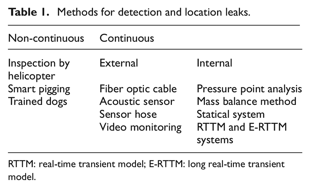
RTTM: real-time transient model; E-RTTM: long real-time transient model.
A leak can be inferred by using the pipeline parameters above. The leakage detection method chosen for a pipeline depends on several factors, including product characteristics, pipeline properties, instrumentation, communication, and economics. Pipelines differ considerably in their operational functions and physical attributes, which means there is no single internal or external method that can be applied universally. 18
A chosen LDM must employ performance criteria and demonstrate sensitivity, reliability, accuracy, and robustness. Nonetheless, any performance criterion is contingent upon detailed knowledge of degradation in respect of the mechanical properties of pipes and their correlation with damage propagation and ultimate failure. Traditional LDMs, such as monitoring changes in flow and pressure, cannot be applied to detecting WDN background leaks and are incapable of adequately satisfying the leakage detection requirements in water distribution pipelines that are geographically dispersed.
Greater effort should be allocated to this type of leak because it accounts for a greater percentage of water loss than other types of leakage. In one of the earliest review papers on this topic, Morris 16 provided an introduction to factors that may cause leakage in water pipes, and a summary of several leakage control methods was published by De Paola et al. 17 The principal characteristics of the different leakage detection methods were compared by Cist and Schutz 19 and another categorization of LDMs was carried out by Liou et al. 20 Datta and Sarkar 21 also reviewed methods of calibrating water lines (including leaks). Other review papers focused on leakage methods, causes of leaks, mechanisms of pipe failure, and the role of statistics and modeling in pipe failure detection and leakage localization in a very comprehensive manner.16,18 However, when these reviews are assessed with a critical eye, it seems that a comprehensive review study is still required to evaluate how effective current LDMs and LLMs are against prominent degradation mechanisms.
To differentiate this research from others, which typically focus on leakage, a detailed analysis of LLMs and LDMs was undertaken to outline their advantages and disadvantages in the context of degradation in joints and pipes. Focus was allotted to these issues when selecting resources22,23 and an in-depth categorization of performance variables and their significance in network degradation was used to determine detection method feasibility. Moreover, through the use of simulation models and calibration factors, it has been possible to determine the fracture toughness of metal pipes and how they degrade.24,25 The next section provides the key principles associated with the degradation of pipes and which are thus fundamental to developing effective LLM and LDM strategies.
Following this introduction, a classification of pipe performance parameters is provided in section 2. This is followed by a discussion of fluid flow and piping network parameters in section 3. A critical analysis is provided of the material properties of pipes and their degradation during their working life in section 4. The effectiveness of fracture toughness reduction for quantifying leakage is presented in section 5. A discussion on the effectiveness of LDMs and LLMs in degradation mechanisms is discussed in section 6 and the outcomes are discussed in the last section 7.
Similarities and differences in the deterioration mechanisms of cast iron and steel pipes
The literature demonstrates that corrosion is among the primary causes of failure in underground steel and iron pipes, which makes it a significant concern for pipe network stakeholders, including asset managers and engineers.26–28 Pipes used in underground networks installed prior to the 1980s were typically made of cast iron and steel, 29 of which gray cast iron and carbon steel were the most common. 30 This historical phenomenon underlines why these two material types are used for the purpose of corrosion investigation. More specifically, HT200 gray cast iron and Q235 plain carbon steel have been selected for investigation because of their availability and their widespread usage in the pipe industry, especially in China. The properties of these specimens are provided in Table 2.
Chemical composition of materials.
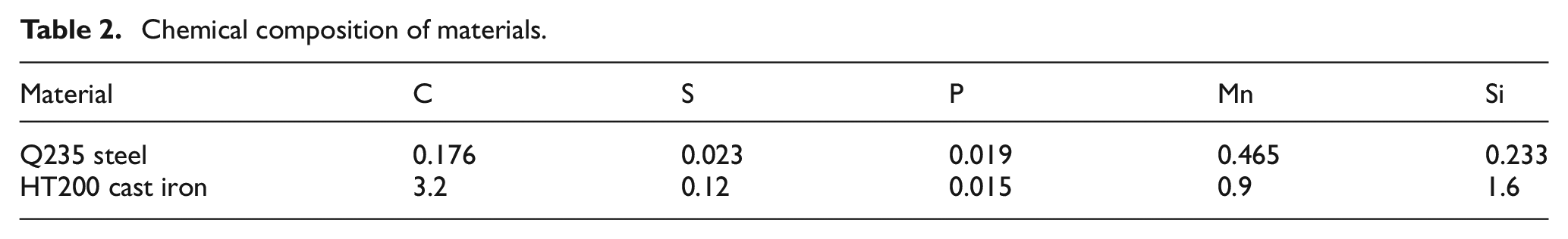
Although the function of cast iron and steel pipes is the same, these materials exhibit different mechanical attributes; for example, they are brittle and ductile, respectively. The use of cast iron preceded that of steel, mainly because of its low cost. However, the former has come to be replaced by steel because of the greater ductility and strength of the latter. The mechanical properties of metals play a significant role in their microstructure, morphology and chemical composition, which all have an impact on pipe longevity.
Classification of performance parameters
Prior to developing an effective leak strategy, it is necessary to comprehend the metal pipeline variables that are linked to external and operational factors. For example, in the case of a municipal water system, several materials make up the network that are contingent upon design details and positioning. External and internal operational practices and geometric and environmental factors are typically blamed for failures in metal pipelines, 31 the most important of which are discussed in the following sections.
Geometric parameters and material properties
Length
Metal pipelines involve two forms of length: a node length between manholes and a section length between joints. As the pipe length in a section increases, this can result in additional stresses because of differential ground movement transverse to the axis of the pipe.
When a pipeline is not adequately supported, the length can cause an increase in beam stresses that can result in pipe degradation, such as circumferential cracking. When a pipeline consists of a node with a length in excess of 500 m, it becomes difficult to maintain. 31
Diameter
The dimension parameter, or tube hole–diameter ratio, affects pipe leakage even though the pipe hole is the same size. This parameter can be utilized to determine the discharge flow, as in equation (1).

Where:
The link between the diameter of the hole and the diameter of the pipeline (or the curvature of the pipe wall) affects the leakage rate, with a large variation in the discharge coefficient (Cd). As the pipe aperture–diameter ratio decreases, Cd values fall consistently. Overall, Cd values also decrease with β (the relation between the pressure head differential at the orifice with respect to wall thickness). Small diameter values can cause “bell splitting” in pipes under varied temperature conditions. 12 In cast iron pipes, molten lead is used to seal joints. However, each parameter has a different coefficient of expansion and thermal expansion will lead to cracks appearing below the bell of the pipeline.
Wall thickness
The thickness of the wall of a metal pipe typically has an impact on operational pressure and depends on the diameter and material of the pipeline. The magnitude of potential pipe stresses is also contingent upon the pipe depth and loading and may also be a function of pipe wall thickness. Wall thickness must be considered when assessing potential degradation, since it has an impact on the time needed for corrosion pitting and hence influences the life cycle of the pipe. Moreover, this parameter has ubiquitous salience for all pipe materials. 31
Pipe age
The age of the pipeline generally corresponds to the difference between the year it was installed and the date it was inspected. Aging is a key factor in pipe degradation. 32 A bathtub curve is a graphic that shows the pipe failure rate by age. 33 The bathtub curve is divided into three different phases, as shown in Figure 2. During the primary phase (early life), defects can occur due to human error and damage to a pipe can be caused by inappropriate materials, installation, and construction. The secondary phase demonstrates the service lifetime of the pipe, when the failure frequency is very low and almost constant.
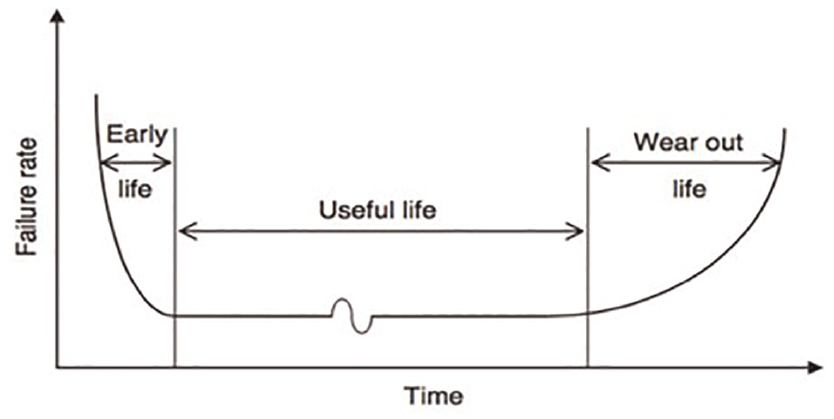
Theoretical bathtub curve of an underground pipe. 34
Several random phenomena, such as extremely heavy loads, ground movements, offsets, or third-party interference, can cause failures at the secondary stage. At the tertiary stage (wear and tear of life), failure frequency is highest because of the aging process. 33 The majority of predictive condition models developed in previous studies indicate that the age of a pipe is significantly related to the degradation of the metal pipe.
Pipe depth
Many features, including pipe material and diameter, the water table, soil type, and regulations, should be considered when determining the appropriate depth of metal pipelines. The outcomes of studies on the impact of depth on pipe degradation are contradictory in respect of various predictive models. For example, Khan et al. 35 demonstrated using their forecast model that pipe depth is an important parameter which, when increased, negatively affects the condition of the metal pipeline. This can be explained by deeper pipes having greater dead loads on them and an increased likelihood of coming across the water table and, as the soil cover increases, the load pressure decreases. In general, metal pipes are subject to more defects and a higher rate of deterioration because of surface loading, tree root intrusion, and illegal connections. However, a greater depth of cover over the pipes reduces the effect of surface factors, including construction activities, vehicular traffic, and road maintenance. 36
Operational parameters for fluid flow
Cast iron pipes formed the backbone of water pipelines in the early-mid last century. However, since that period, engineering requirements have evolved and pipe networks are now required to be able to resist surges in traffic loads and earth pressures. In this context, studies have investigated historic pipeline failures to determine the environmental and physical factors involved. 37 Several investigations found, for example, that failures were more likely to have occurred when long droughts were followed by extended periods of significant rainfall. 38
Operational loads on buried water pipes
An investigation carried out by Robert et al. focused on the impact of operational loads on underground cast iron water pipes located in Sydney in Australia. Several tests were undertaken to consider traffic and water pressure loads on 660 mm diameter cast iron pipe samples located in natural clay soil buried under a roadway. Ground pressure cells and strain gages were investigated to determine the impact of loading on soil stress and pipe deformation. 39
The field data results from Robert et al. 39 indicated that changes in ground pressure and hoop strain caused by traffic loading had a marginal impact on the pipes. Although greater pipe strain was reflected in internal pressure tests, this was still significantly below the expected failure strain for cast iron pipes. This suggests that internal pressure and traffic loading are not existential factors when considering pipe failure prediction, except when coupled with pipe corrosion that results in high pipe stress intensities. Nonetheless, there is a need to examine in greater detail the impact of other factors on pipe stress failure prediction.
Lin et al. developed an innovative technique that used mathematical models, numerical simulation, and in-situ water stagnation experiments to determine the release of iron caused by a switch in water source. This experimental procedure consisted of determining iron release and the accumulation of in-situ water stagnation on sections of Beijing’s cast iron water pipe network following a switch of water to the Danjiangkou Reservoir. Quantitative analysis was carried out to determine the correlation between the iron release rate and other key quality parameters. The methods and resultant data were said to be useful to those involved in switching water sources when trying to prevent “red water.” 40
Water quality and alkalinity effects
Degradation is also caused by water attributes, including buffer intensity and alkaline and pH levels. In the case of the last example, when the pH range falls between 7 and 9, this can result in tuberculation. 16 There is, however, a decrease in the release of by-products at higher pH levels. The literature also states that both iron concentration and weight loss fall as the pH increases from 8.5 to 9.2. 41 Lower levels of alkalinity are typically associated with reduced corrosion and weight loss rates. Moreover, when alkalinity levels have been held at levels higher than 60 mg/L as calcium carbonate (CaCO3), customers were found to complain less about red water. 41
Dissolved oxygen
Iron degradation can occur because of dissolved oxygen concentration; that is, as DO increases, so does the rate of degradation. 42 However, the impact of tuberculation and iron concentration may differ depending on the type of scaling. The literature indicates that lower oxygen saturation levels result in higher turbidity (an iron concentration surrogate); however, there are also reports that show DO-free water will not tuberculate. 32 DO can also reduce corrosion through phosphates, which can buffer ions. For instance, in water with DO < 1 mg/L, four phosphate solutions exhibited a greater corrosion rate in comparison with non-phosphate water; in water with 1−6 mg/L DO, the observation was reversed. 32
Fluid velocity
Fluid velocity plays a significant role in pipe corrosion. It is commonly assumed that greater levels of corrosion will be caused by increased flow because of higher oxygen levels. This can result in the protective layer being subject to precipitation, resulting in degradation. The literature shows that in the case of mild steel, there was a decrease in weight loss as water flow rates increased when the DO was saturated,33,42 in addition to scouring of the protective scale. However, there is also evidence that suggests denser protective layers at higher water velocities.
Operational pressure
The pressure of a system can be maintained using pumps and valves, which results in hoop or tensile stress acting on pipes. This stress can be described according to operational pressure and the thickness and diameter of the pipeline. When tensile stress passes a given threshold, this results in longitudinal cracks appearing on the pipe wall. Pipes, valves, and joints are also subjected to operational pressures that cause axial stress, which can lead to circumferential cracking. 31
Temperature
The literature indicates little focus has been given to temperature and its impact on pipe degradation. 43 Moreover, as reflected by the Pilling–Bedworth ratio, the heterogeneous scales of the iron formed on pipes can make significant differences to physical properties, including scale density and thermal expansion coefficients. When exposed to cycling or temperature gradients, this causes stresses in the scale and cracks that can result in leakages. The literature indicates that only a few studies have evaluated the impact of temperature on the degradation of a distribution system. For example, an investigation revealed a decrease in weight for iron samples held at 13°C as opposed to 20°C. 44 Additional investigations indicated fewer complaints concerning red water and lower iron concentrations during cold seasons. Lastly, two pilot studies indicated changes in temperature were coupled with high levels of metal concentration and turbidity. 44
Free CO2
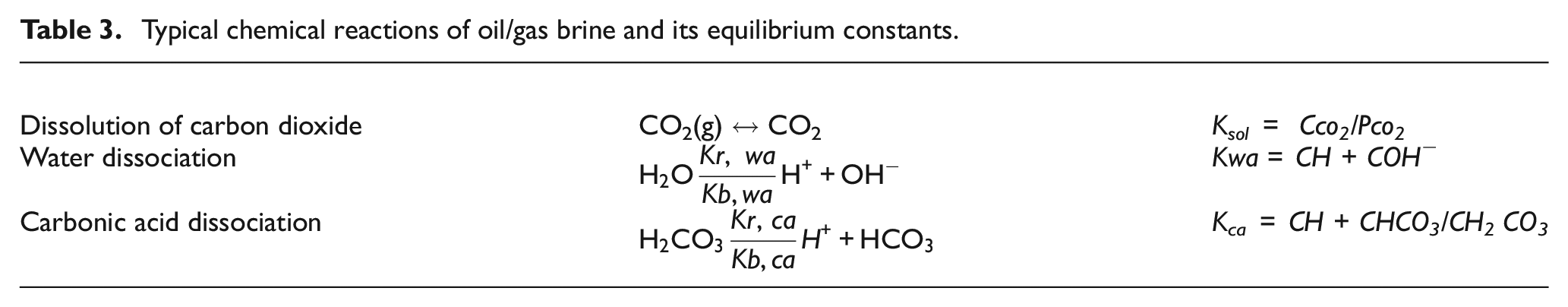
Studies have emphasized the salience of “free CO2,” the sum of dissolved carbon dioxide and carbon dioxide. A study has shown that free carbon dioxide forms surface complexes over iron oxide, which increases the solubility of ferrous iron and causes an increase in iron concentration and the degradation of iron pipelines. 45 The same thing happens with dissolved H2S which also passes through two dissociation steps and acetic acid which dissociates into one step. Table 3 provides a list of the most common chemical reactions that must be considered in brine chemistry. Different salts may precipitate if their solubility is exceeded, the most significant being iron carbonate FeCO3, and different types of scales that are typically calcium rich (CaCO3, CaSO4, etc.). 46
Typical chemical reactions of oil/gas brine and its equilibrium constants.
Manufacturing flaws
Several methods are used in cast iron pipe production, two of the most important being centrifugal and pit casting. Centrifugal casting produces better tube results because of more robust microstructures when compared with pit casting. 47 Proponents, including have highlighted manufacturing flaws associated with gray cast iron pipe production. Others, such as Maker et al. have noted that spin casting can be used for ductile iron pipelines. However, organizations such as the Canadian National Research Council have not investigated ductile iron failures. 12
Impact of porosity
In pit-cast iron pipes, porosity is the most common manufacturing defect and is produced by air that rises in the pipe before it has solidified. This phenomenon is less acute in gray iron pipes, in which air can more readily escape through the inner wall of the pipe. Nonetheless, this still results in material loss in metal pipes and leads to degradation. 12
Impact of inclusions
Inclusions are unintended additions that find their way into materials. These materials then cause stress concentrations, decrease the cross-sectional area of the pipe, and result in crack formations. 12
The above performance parameters and material properties play an important role in pipe degradation mechanisms. In the next section, the above terms and their explanations are used to describe the relationship between them and prominent degradation phenomena.
Correlation between degradation mechanisms and performance parameters
Although a comprehensive understanding of pipeline failure could not be found in the literature, three features are proposed. First, the installation procedure and materials utilized, the interaction of the soil with the pipe, and the properties of the pipe. Second, operational pressures, resulting in external and internal loads due to site interference from unknown entities, such as vehicles, extreme weather, and soil overburden. Third, factors leading to operational pressure caused by the external and internal biochemical, electrochemical, and chemical environments. The manner in which underground pipelines behave is structurally understood; however, there are also unknowns, including the impact of material damage and frost loads on structural performance. This reality explains why great efforts have been undertaken to comprehend the physical processes linked to the breakdown of buried pipes. In metallic pipes, there are two primary degradation mechanisms: corrosion and embrittlement. The following subsections explain how these two mechanisms result in degradation.
Hydrogen embrittlement
A common cause of pipeline failure is associated with atomic hydrogen seepage into interstitial spaces, which involves the migration of hydrogen through metal pipes, as follows:
Atmospheric absorption of molecular hydrogen (H2) from the immediate environment into the metal lattice of the pipeline.
The manufacturing process of pipes introduces hydrogen into the metal lattice of the pipeline.
Precipitation of hydrides and the presence of hydrogen-generating species and/or electrochemical reactions, such as corrosion.
Environments rich in hydrogen sulfide (H2S) increase the likelihood of pipeline cracking, as this raises the potential to poison the hydrogen recombination process. The subsequent hydrogen attack results in pipe leakages or complete failure, which causes significant economic loss to operators in addition to environmental damage. 48 This, in addition to the aforementioned problems, underlines why pipeline metals must be engineered with high levels of robustness.
In the case of high-strength pipeline metals, cracking occurs prior to sulfide corrosion, 49 indicating a direct correlation between the mechanisms and different types of hydrogen degradation. Nonetheless, the fabrication and welding methods of metal pipes need to minimize microscopic defects to ensure hydrogen atoms do not cause problems after a pipe enters service. 50 Several common forms of hydrogen degradation are provided below.
The damage caused by hydrogen depends on various parameters, such as the type of metal and its microstructure, as these determine the hydrogen-trapping potential. As shown in Figure 3, hydrogen is typically trapped along the interface, defects, dislocations, and grain limitations. Moreover, crystalline imperfections, such as those mentioned, attract hydrogen atoms. This phenomenon has attracted a significant amount of research recently, leading to extensive research on hydrogen and its isotopes. 45
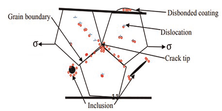
Schematic of hydrogen trapping at different pipeline locations. 51
As noted earlier, the mechanisms associated with hydrogen degradation are complex, which underlines why it is necessary to understand how hydrogen is accumulated and transported, resulting in molecular defects. Locations in the network of crystals where hydrogen atoms are less likely to pass without being rigidly trapped, such as inclusion interfaces, 52 are potential high energy barriers to those sites that need to be overcome in order for hydrogen atoms to escape.
Wu et al. 53 and Roquefere et al. 54 assumed that hydrogen atoms that are permanently trapped are not included with those that diffuse through metal. In contrast, sites rich in trapped hydrogen, which needs a low energy potential to escape, may be described as reversible sites. However, methods such as neutron diffraction may be suitable for hydrogen interaction with metal compounds. Hydrogen embrittlement (HE) can result in material cracking caused by a combination of critical stress levels and specific amounts of hydrogen. Although this idea is accepted in principle, there is no consensus concerning how this mechanism occurs. Nonetheless, examination using advanced techniques associated with fractographic analysis has revealed the role of hydrogen in dislocations based on specific principles. 55
Hydrogen-induced decay between metal bonds that results in decohesion (but not slipping) is termed hydrogen-enhanced decohesion (HEDE) and results in metals exhibiting little plasticity and a smooth brittle fracture surface. HEDE is typically associated with steel HE mechanisms. Decohesion as an HE factor links material failure to reduced atomic bond strength due to hydrogen segregation to defined interfaces, such as the grain limit. When the cohesive force
Proponents such as Birnbaum 56 have stated that atomic hydrogen decohesion can occur (i) as an absorbed species at cracked tips, (ii) in front of cracks at particle matrix pivots, and (iii) at locations subject to high hydrostatic stress. Improved localized hydrogen flexibility suggests increased deformation in specific regions caused by certain temperatures and deformation rates. Atomic hydrogen within the material composition reduces displacement movement stresses. 57 Since these sites are in close fracture surface proximity, the damage procedure is described as a localized plastic-type fracture, not embrittlement. 52
In their study, Okonkwo et al. 58 carried out a detailed examination of localized plasticity and noted the impact of hydrogen on the speed of screw dislocation in α-Fe. Nonetheless, several questions are still unanswered in the context of hydrogen-induced cracking enlargement in relation to (i) increased crack formation rate relative to hydrogen diffusion rate at the tips, and (ii) the contribution of hydrogen to improving plasticity as well as the likelihood of fracture. Nazarova et al. 59 demonstrated that temperature increases in proximity to a pipe result in decreased SCC susceptibility. For pipes operating in an H2S environment, optimum temperatures were defined as being between 20°C and 50°C due to a protective mackinawite (FeS) film. 58 When this upper limit is exceeded, spalling occurs in the passivation film, resulting in hydrogen infiltration and damage such as cracking.
Within the temperature range referred to above, passivation film may be subject to spalling, resulting in hydrogen infiltration and cracking. Biezma 60 comprehensively assessed the impact of hydrogen in microbiologically influenced corrosion, SCC, and the decatalysing of hydrogen recombination reactions on metal surfaces. Crack conditions are altered by H2, causing embrittlement and tensile stresses, problems that are compounded when H2 is trapped in locations under different forces. The impact of bacterial activities on a biologically active environment (BAE) was also investigated on metallic surfaces. The author concluded that BAE supports hydrogen diffusion into metals when conditions are anaerobic. Nonetheless, to comprehend hydrogen concentration profiles in complex systems fully, a significant amount of research needs to be undertaken.
Corrosion
Corrosion refers to the adverse effects of the environment that ultimately lead to material failure, as shown in Figure 4. Moreover, with regard to metal pipe networks, corrosion refers to electron release due to anode site dissolution and electron transfer from cathodic sites, whereby hydrogen peroxide is reduced to hydroxyl ions (OH-). Moreover, chemically transformed hydrogen can also produce hydrogen gas. 61 The redox process forms part of the corrosion process and can be mathematically represented in two half cells and in overall responses, as per equation (2).

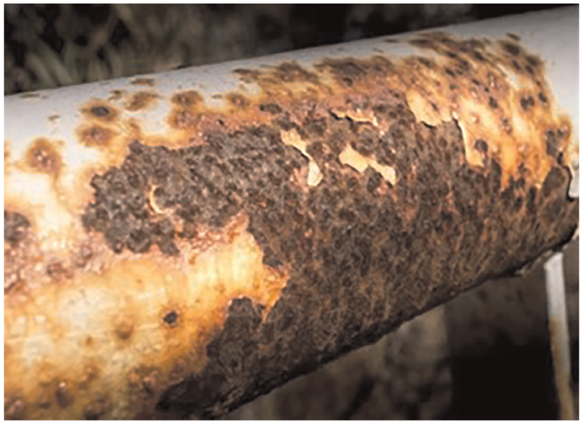
Corrosion in a pipeline and metal skin. 62
Figure 5 shows the anode and cathode electrons typically found on a pipe exterior; however, for corrosion to be successful, an electrolyte is needed for ion transportation. Pipelines used to transport oil and gas often carry corrosive fluids, such as microbes, CO2, sand, and H2S, in addition to organic compounds.
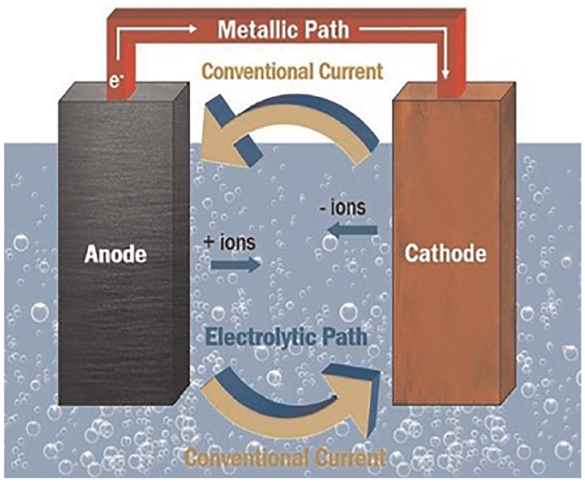
Basic corrosion cell. 62
The literature and industrial data suggest that metal corrosion in steel and iron is the most salient cause of degradation in pipes. 63 Since corrosion is a worldwide issue, it can be considered a global issue for stakeholders, especially for investors and engineers who manage underground pipe networks. 28 This phenomenon has spurred a significant amount of research in the previous decades, including studies by Dean and Grab 64 and Camarinopoulos et al. 65 Corrosion mechanisms differ depending on environmental factors. For example, internal corrosion may be caused by microbial effects, and external corrosion is typically linked to the immediate soil containing corrosive chemicals. The latter form of corrosion depends on how the pipe interacts with its environment, which may contain an adverse or excessive amount or level of mineral salt, sulfides, organic matter, moisture, pH, precipitates, temperature, and other factors. 66 Depending on the soil chemistry and physical properties, the aforementioned variables will have a specific type of impact on a pipe.
Most recent analysis has focused on corrosion velocity, progression, and mechanisms and has approached these problems from a materials perspective. However, relatively few investigations have been undertaken to assess the impact of mechanical properties leading to a change in pipe material. Moreover, even fewer data are available on the way in which corrosion has an impact on pipe fracture toughness.
The materials used also have an impact on the potential for pipe failure, which means it is necessary to assess how mechanical properties are affected by metal corrosion since action could then be taken to mitigate such failings. Pipe failure can be categorized in a dual manner: rupture and fracture modes, whereby wall thickness is compromised and stress is concentrated at the tips of cracks, respectively. These types of failure are contingent upon the tensile strength and fracture toughness of the pipe matrix. The majority of the recent literature in this area, such as work by Hou et al. suggests that most researchers have focused on the loss of strength, as opposed to toughness. Inspections carried out on cast iron trunk sections indicate failures are caused by crack propagation leading to pipe collapse. 61 This underlines the salience of investigations associated with fracture toughness and tensile strength to better predict pipe failure.
Rajani and Kleiner
15
carried out an experimental study that tested iron pipes and pits in the absence and presence of corrosion. Mechanical test results were used to determine the impact of the geometry and dimensions of the corroded pits on the residual strength of gray cast iron water pipelines and it was concluded that the nominal tensile stress (
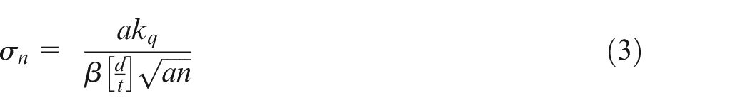
Where:
β: geometrical factor depending on the shape and dimensions of the corrosion pit.
D: depth in the pit
T: thickness of the wall of the tubing
Equation (3) can be likened to the principal equation of fracture mechanics. Wan and Zhang used an experimental setup that made use of two thick pipes with a 100 mm diameter and one long thin pipe with a diameter of 10 mm. One of the thick pipes had a circumferential crack. Pressure sensors were attached to the long thin pipeline with a partial crack model. After inducing a leak in the system, it could be seen in the form of a stripped circumferential crack in the thick pipe. In a steady-state scenario, the pressure applied to the side of the crack was less than the residual strength, which did not result in degradation or lead to leakage. With an increase in pressure, the discharge increased, resulting in a leakage jet that subsided after pressure loss, followed by intermittent leaks. Iterations of high and low water pressure resulted in a phenomenon known as water hammer. 67
An experimental study performed by Greyvenstein and van Zyl 68 measured leakage exponents of several different leak opening types, such as circumferential and longitudinal cracks and corrosion holes. Figure 6 shows a network with two removable end sections: one end is linked to a municipal network using a combination turbine flow meter and the other is linked downstream using a pressure transducer that acquires flow data.
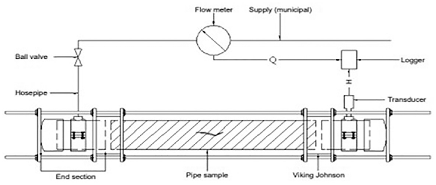
Experimental setup. 68
When flow and pressure were low, fluctuations were also smaller. Experimental data were acquired from stable sections of the network and averaging the data when the values acquired significantly differed from this average allowed the leakage exponent to be pinpointed. 68
Below-grade concrete structure leakages are frequently fixed using different grout-injection materials. However, the choice of material is not conducted based on factors which lead to environmental degradation. In one study, samples were placed in a water flow for 48 h, subjected to test cycles and then put in a desiccator until samples reached a constant mass, which was then measured. The grout-injection material loss ratio was measured based on the results from the washout resistance, 69 as shown in equation (4).
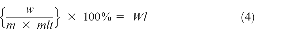
Where:
m: grouting-injection material mass prior to testing (g)
mlt: mass loss threshold (%)
W: loss of grout injection material after water run-out (g)
WI: mass–loss ratio compared with the standard mass–loss threshold
The mass lost must not exceed 15%, as, according to the KS F 4935 standard, if there is a loss of mass of more than 15%, it would lead to degradation of the sample and produce leakage.
The above analysis shows that deterioration in pipe material is linked to changes in the composition of the components. There is also an indication that these changes are the main reason for degradation in mechanical properties. Therefore, understanding the link between the variables and a degradation mechanism is a significant step toward better comprehension of leakage detection. Moreover, the literature indicates there is a need for further research into the mechanical properties of steel pipes, including fracture toughness and the impact on leaks.
Circumferential cracks
Longitudinal stress placed on a pipe will typically result in circumferential cracks that are caused by pipe bending Talbot, 70 and/or by temperature changes that result in axial tension. 71 Bending may be the result of environmental factors, which include changes in water temperature, expansive soils, differential settlement, ground movement, bedding loss, and rock impingement. Pipes that have a diameter of less than 200 mm are more susceptible to circumferential cracks, which are the cause of 80% of all failures. 26 Circumferential cracks may also occur due to graphitization and corrosion pits. Maker et al. 72 have reported that up to 90% of circumferential failures occur when corrosion pits are present.
Longitudinal cracks
Longitudinal cracks are typically caused when excessive circumferential stress occurs, leading to internal pipe pressure, along with geostatic stress, a phenomenon that is more acute in pipes with a large diameter. 60 However, longitudinal cracks can also be accelerated because of external loads, such as traffic and snow.
Human factors
The literature indicates that human intervention is also a cause of corrosion in water main networks made of cast iron. Several causes have been identified, including network negligence, third-party damage from excavation, installation methods, and poor design. 73
Reduction in fracture toughness effectiveness during leakage quantification
Since the 1960s, engineers have been developing reliable fracture toughness test methods that are now considered crucial. This led organizations such as the American Society for Testing and Materials (ASTM) to develop comprehensive testing standards and review techniques, of which ASTM E1820 and E399 are the most common.74,75 ASTM E1820 is used to assess the deformation of elastic plastic strain frequency,
Investigations of circumferential surface cracks indicate that the fracture curves at the surface of a cracked pipeline are generally located on top of the through wall of the cracked pipeline curve. However, this means it is not possible to predict load-controlled leak behavior. The load-controlled leakage of axial and circumferential surface-flawed pipes could be understood through the relationship between a decrease in toughness and increasing flaw depth. Wilkowski et al. 76 carried out an empirical analysis that considered the axial surface crack bulging factor and found an inherent link between a change in toughness and flaw depth and noted the minor impact of bulging to determine leakage.
It should be noted that it is not possible to predict load-controlled leakage using net-section-collapse (NSC) limit-load analysis for circumferential surface cracks; nonetheless, leakage has occurred in surface-cracked pipe experiments. This can be attributed to the failure mode, as this transforms from a load-limit mode to a plastic-elastic fracture mechanics failure mode as a/t increases, even in the case of wrought TP304. 76
In other work, Monte Carlo simulations were undertaken with samples of crack 106 and fracture toughness and yield strength and ultimate value distributions were first calculated. Failure assessment diagram analysis was conducted under typical operational conditions and critical lengths for circumferential and axial cracks were determined in an iterative manner, as shown in equation (5).
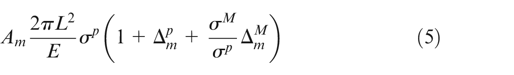
Where:
Am: crack opening area
L: half-length of the crack
E: Young’s modulus
Displacement and crack opening angles were also calculated, in addition to estimating leak rates using the Henry–Fauske (though modified) model for different types of cracks. As shown in Figure 7, crack morphology had a significant impact on the results scatter, and even more so relative to the mechanical properties scatter. Using the statistical data, the probability of leakage failure could be determined.
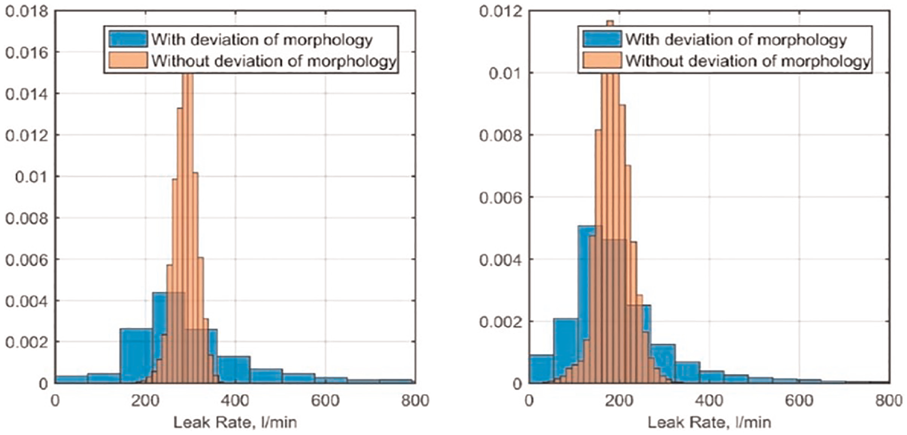
Leakage rate for SCC intergranular cracks under normal conditions of operation: axial (left) cracks; circumferential (right) cracks. 77
In Figure 8, the ultimate yield strength has less influence when compared with fracture toughness, which is in line with Dubyk’s results. 78
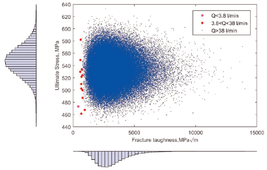
Probabilistic analysis of fracture toughness (KIC) σul space for intergranular SCC cracks. 78
This failure probability can be considered the acquisition of critical cracks in piping, and the leak rate would be undetectable. The outcomes of the analysis can be seen in Table 4. The critical crack length is aligned with a typical normal distribution; however, the Weibull distribution is more suitable for leak rates. 78 A leakage rate model should be developed in future work, as the Henry–Fauske model has a drawback for two-phase physics, since leakage rate characteristics should be treated precisely for nuclear safety.
Typical means and deviations for critical lengths of crack and leakage rates.
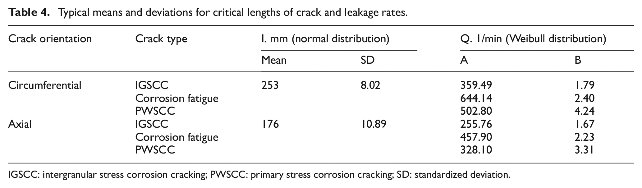
IGSCC: intergranular stress corrosion cracking; PWSCC: primary stress corrosion cracking; SD: standardized deviation.
A study by Nyhus et al. identified pipe information and single-edge notch tension (SENT) three-Test data with varying a/t (a/w for SENT) ratios (the same orientation as the crack) and demonstrated a correlation between decreased toughness and an increased depth of crack. Notably, in this study, the SENT results provided lower toughness values in relation to a circumferential surface-cracked pipeline, as shown in Figure 9. A commonly held opinion was that SENT test subjects would demonstrate a greater consistency with surface-flawed pipes 79 from previous studies using SENT with H/w = 10 and a/w = 0.3.
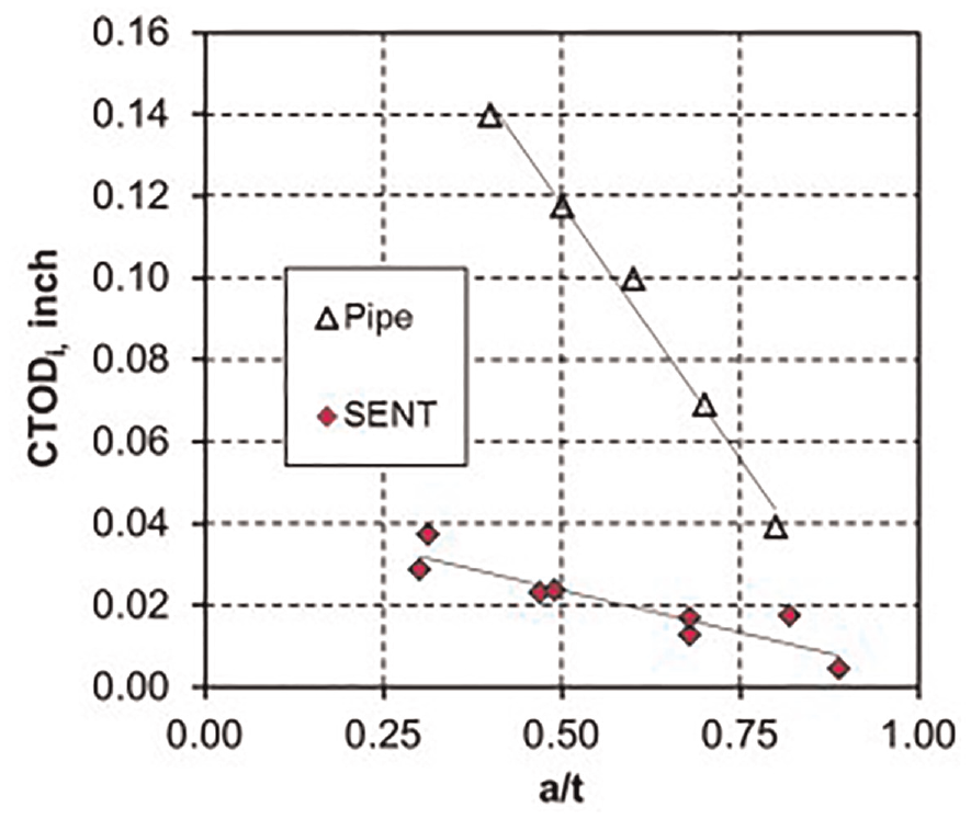
Comparison of CTODi values for surface cracking tubes versus SENT samples. 80
Nomenclature
A Crack depth
H SENT specimen height between grips
T Pipe thickness
W Sent specimen width
A discrepancy in toughness may be attributed to the curvature of the pipe. In particular, tests on circumferential surface-cracking pipes may limit ligament rotation, whereas SENT experiments with H/w = 10 enabled this rotation. However, in typical conditions, tension should provide greater toughness, whereas bending results in lower toughness. In order to understand the discrepancy and align the results with supporting literature,81,82 lower toughness with greater flaw depth can be used to explain why “Apparent net-section-collapse (NSC) analysis” was required to predict overload controlled leakage behavior for pipes with circumferential surface cracks.
Studies available in the literature suggest various flow maps (Fauske, 1962; Moody, 1965, 1966, 1975). Fauske (1962) put forward a method for predicting critical flow rates in the context of a choked condition; that is, choke quality and pressure. The model introduced a slip ratio that is described by minimizing the energy of a two-phase mixture. However, Fauske’s map (1962) provided an instructive meaning only when the choke conditions were known. Typically, choking situations are contingent upon upstream conditions that include pressure and enthalpy. The method Fauske (1962) provided was developed further by others, including Henry (1968), and included theoretical upstream conditions; however, no map was suggested. 83
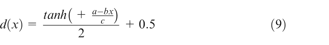
Rahman et al. 84 also employed the Henry–Fauske flow model, albeit following modification. Their approach assumed surface roughness in addition to the length of the flow path and number of turns to be functions of COD at the center of the crack. For example, surface roughness is mathematically explained in terms of COD function, as follows in equations (6)–(8).
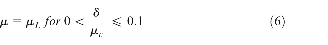
Where μl and μc are the local and overall surface roughness, respectively, and δ is the COD in the center of the crack.
The Henry–Fauske two-phase flow model can be used when the wall thickness–hydraulic diameter ratio has a value greater than 30. In this scenario, the length of the flow path, number of turns and the surface roughness of the pipe were also considered to be COD functions. A similar leakage ratio to the modified Henry–Fauske model was exhibited when there was a short crack length. However, there was a larger leak rate since there was an increased length of crack when utilizing crack morphology parameters for primary water SCC weld and SCC fatigue, and cumulative density function was acquired for the leak rate. 85
There also appears to be a gap in the literature concerning the impact of corrosion on pipe fracture resistance in simulated soil solutions. Chatzidouros et al. 77 simulated a soil solution (NS4) when exposed to hydrogen, and others, such as Wenman and Dim, 86 assessed the short-term impact of corrosion on the fracture toughness of metal pipes when exposed to different pH levels. These studies typically have inherent weaknesses associated with them. For example, the latter used manufactured soils with properties not found naturally. Moreover, although data on hydrogen corrosion were provided, no toughness testing was performed.
Effectiveness of LDMs and LLMs against possible leakage
The literature contains several proposals for pipeline LDMs.80,87,88 Existing leak detection techniques involve hardware and software methods. Adegboye et al. 89 classified these technologies based on their technical attributes, which resulted in a tri classification schema of external, visual, and internal methods.
External technologies are used on the exterior of a pipe and check for leaks using sensing devices. Visual-based methods detect pipeline leakages using drones, personnel, and trained animals, such as dogs and pigs. Currently, these solutions appear to be the best answer to leak detection and localization. However, these methods require operational time, which has an impact on inspection frequency. Internal-based leakage detection techniques can also be used for leakage localization and detection. These techniques typically use computer algorithms alongside sensors to form monitoring parameters that quantitatively describe the flow of fluid within a pipeline, and include methods such as dynamic modeling, 90 state estimators, 91 pressure point analysis, 92 and mass–volume balance. 80
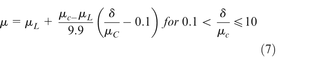
In other research, acoustic detection methods were applied to 300 mm diameter ductile iron pipes. Open taps were used to mimic leaks and associated sounds were captured through acoustic loggers from leak and non-leak specimens. 93 The data acquired from the fixed sensors are reproduced in Figure 10, which demonstrates an attenuation trend as per an increase in leakage point distance.
Acoustic detection performance using a multi-sensor in high sensitivity mode. 93
An ensemble transfer learning one-dimension convolutional neural network (TL1DCNN) formed the basis of a pipeline leak detection and localization technique, which was further enhanced by integrating it into a 1DCNN. The TL1DCNN base learners and associated weights were optimized through particle swarm optimization (PSO). Leakage localization and detection were then acquired through an ensemble TL1DCNN. This method is advantageous since data can be extracted automatically as opposed to manually when using typical data drive methods. Moreover, the ensemble model approach also results in performance advantages due to optimal parameter selection using various combination strategies, batch sizes, epochs, learning rates, etc. 94
The TL1DCNN model proposed by Wang et al. was trained on a small data set, resulting in high-performance pipeline leak localization and detection. The system utilized a fiber Bragg grating (FBG) sensor that monitored internal corrosion and pipeline leakage. Following calibration and testing, the results demonstrated that the FBG pipe-fixture sensor could mitigate the large discrepancy between the theoretical and test values and eliminate the limitation of measurement range. Sensor data were further corroborated through internal pipe corrosion monitoring and a leak detection test on pipe samples with differing degrees of corrosion and leaks. concluded it was possible to use the FBG pipe-fixture sensor to detect pipe leakage and decrease the localization error of the leakage point to within 1 m. 95
Leakage detection can also be employed based on artificial neural networks with back propagation algorithms using acoustic signals. This system comprises three layers: a hidden layer and an input and output layer. This solution provided an estimation accuracy of 97.2% and 96.9% using the feature set {Peak, Mean, Peak Frequency, Kurtosis} and {Mean, Peak Frequency}. The results indicate that the use of frequency and time domains significantly reduced false alarms. 96
Proponents such as Aljuboury and Rizvi attempted to assess impacts on leaks by using a novel metallic bolted flange point and 3D finite element analysis (FEA) and ANSYS software. A model was made of fluid leakage propagation between the flange and the gasket based on the pressure-penetration criterion (PPCN) in ANSYS using element real constants. Bolt loads of 10 and 17 KN were applied to the system alongside internal pressure, resulting in a leak. The results indicated that the PPNC and FE approach to leakage study was an efficient and more cost-effective method than experimental testing. 97 Other research forwarded a novel vision-based algorithm that located loose bolts on flange connections, 98 and Park et al. 99 proposed a solution that specifically focused on detecting loose bolt joints on wind turbines but could also be applied to leak detection applications.
Monitoring gas and oil pipe networks can be done remotely using wireless sensor network (WSN) technology, an advantageous method because it offers fast responses, low cost, and leakage localization capabilities. However, to acquire comprehensive benchmark performance, further research is required into leak localization, sensing coverage, and sensing modality. Several sensors are currently available for detecting pipe leaks using a variety of sensing modalities. Typically, sensory hardware is installed on pipes in which steady-state conditions are expected. Anomalies such as changes in pressure, temperature, vibration, etc. are then made known. One of the main disadvantages of using sensors is their effective scope of detection, which means that leaks can be difficult to detect accurately and additional sensors may be required. In other words, one of the main challenges associated with sensory solutions is optimal placement and the relaying of data. Adegboye et al. identified several of the most common design challenges associated with WSNs that result in suboptimal design. Problems are typically associated with energy harvesting, energy-saving routing, sensor coverage, optimal sensor node location, fault tolerance, and self-organization. 89
According to Liu et al. 100 real-time or dynamic modeling is the most sensitive of the techniques. It makes use of preservation equations for the energy, momentum, and fluid mass of the movement within a pipe and assesses the expected and measured values to determine and describe leaks. The key parameters assessed in this technique include pressure, flow rate, and other fluid-flow variables. The literature commonly discusses pipe leak detection by means of an approach based on transient leaks,101–103 a method that has successfully demonstrated its applicability in locating and detecting the position of a pipeline leak. De Sousa and Romero studied the impact of oil leakage on flow and pressure characteristics using the ANSYS Fluent basic flow simulation software. The results showed the impact of flow rate and pressure within the leak area. Others, such as Molina et al. 104 undertook numerical modeling supported with data from experiments that mimicked leaks in pipes. Specifically, they reported the transitional modeling of incompressible flow in short pipelines with leakages. Experimental and simulation results proved to be complementary, especially for the pressure drop at the point of leakage.
Most of the research available tends to focus on single-phase flow, with little attention given to multiphase pipeline leakages. This is perplexing, given the widespread use of multiphase flow systems in industries that include the chemical, oil, and gas sectors. Rapid detection methods are needed due to the critical nature of these pipeline networks. Kam 105 developed a simulation which attempted to detect pipe leakage, focusing on the positioning, size, and impact of leaks on flow parameters. However, investigations such as this typically have inherent weaknesses. For example, Kam 105 used a single-dimensional pipeline made up of small networks, wherein one network was used to model flow behavior. In other work, Figuerido et al. 106 investigated the dual-phase flow impact of the behavior of leaks in horizontally oriented networks and considered longitudinal leak localization in stratified flows. Figuerido et al. 106 determined that stratified flow systems could adopt typical pressure profiles utilized in monophase leaks. However, similar to other studies, this research simulated single-dimensional pipelines, which are inadequate for gaining a holistic comprehension of the dynamic nature of multiphase flow networks. These drawbacks prevent the conclusions of these works being applied to 3D pipeline networks.
Fortunately, there are solutions to this shortcoming in the form of 3D computational fluid dynamics (CFD) modeling, which has the potential to assess problems associated with complex multiphase flow systems. 107 This approach uses empirical models that are realistic for multiphase pipeline leakages. CFD modeling provides operators with an opportunity to utilize specific pipeline configurations and offers high levels of information on multiphase workflow systems that could be hard to acquire using physical experimentation or analytical models. 3D CFD modeling is particularly useful for assessing the impact of the radial location of a leak along a pipe circumference in relation to the interface of gaseous liquids.
In their study, Araújo et al. 108 assessed the impact of leakages in a horizontal pipeline using the hydrodynamics of the two phases of oil–water flux. Simulations were carried out using the Eulerian–Eulerian model in ANSYS CFX analysis, assuming water and oil as a dispersed and continuous phase, respectively. Part of the experimentation involved changing the oil volume fraction at the pipeline inlet. The researchers found the oil released at the leakage site reached a steady value of approximately 0.4 s in all simulations. However, the study was limited because it focuses on the impact of a leak prior to the flow stability time and, moreover, no flow pattern was specified, which limits the applicability of the findings more widely. In addition to the impact of longitudinal and radial leak positioning, multiple leaks and leak sizes largely remain uninvestigated. To comprehend more fully the behavior of fluid flow induced by leaks, some studies considered leaks in a multiphase pipeline prior to and after the flow stability state. The motivation behind one research study 97 was the lack of literature in respect of pipeline leakages that have more than a single phase at a time. Although several research efforts have investigated monophase pipeline leakages, significantly fewer data are available on multiphase pipeline systems. This has been reiterated by proponents such as Behari et al. 109 who noted that leak detection methods failed to address multiphase pipeline leakages. This is problematic, since single pipeline leak issues do not necessarily apply to multiphase pipeline systems.
Leakage locations have typically been measured using the shortest distance with
Where
The leak function can be used to determine a confidence value for leaks around the source of a flow measurement. Once a leak has been detected, this function can be applied as a kernel, and utilizing the confidence, product, and distance functions it is possible to model leakages effectively using flow data and a leak function. 110 The salient feature of the investigation was the use of the gradient of soil temperature as a prospective indicator of leaks. Another study proposed a successful small leak detection procedure based on doubling the magnitude of the gradient. Using the temperature of the outer wall of a supply line, it was possible to obtain the temperature of the interior insulation. A volumetric leakage flow volume of 500 L/h was acquired following a preliminary measurement of the volume of filtered water at a given time. 111
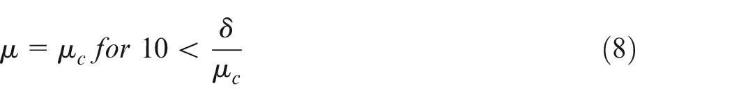
In one study using acoustic detection tests, leaks were simulated with open valves and simulated leakage sounds were acquired using acoustic recorders. Measures were acquired for non-leak and leak conditions to monitor environmental and active leaks. After analyzing the noise intensity prior to and after the leakage, the data showed an attenuation trend as the leakage point increased in distance. 93 Hu et al. 112 proposed spatial grouping using the density-based spatial clustering of applications with noise (DBSCAN) and multiscale fully convolutional networks (MFCN), the DBSCAN–MFCN model, to solve the leak detection problem through the simulation of pipe pressure. The data were normalized according to equation (10).

Where
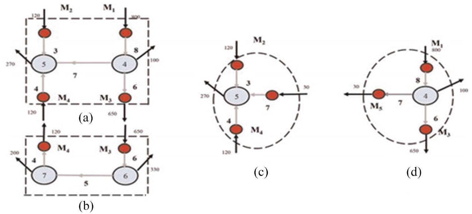
Partitioned network: stages (a, b, c, d) (a) and (b) Sensors in pipes 4 and 6 (c) and (d) Water balance over node 4. 113
The flow through pipes 4 and 6 were 120 and 650 units, respectively. In Figure 12, the flow shows a 20-unit imbalance, which means the leak is located at node 5 or 4. The water balance of node 4 points to a leak in node 4. 113 An inverse model was made by Ren et al. 114 mainly for the detection of leaks in WDNs. Several corrosion levels were simulated using a local corrosion model. Figure 12 presents results that display linear variation in the circumferential medial strain at the angle of corrosion with a linear coefficient of 0.9796 and 0.9993.
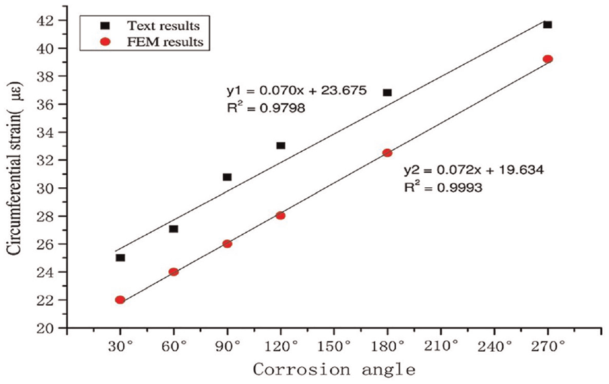
Change in peripheral deformation of various corrosion angles by finite element method (FEM). 115
This result demonstrates that when a wall thickness is constant, the typical circumferential strain is relative to the corrosion angle of the pipeline. The experimental results demonstrated the suitability of using FBG hoop-strain sensors when attempting to monitor pipeline corrosion. 116 Considerable work has been done to date to develop model-based leakage detection methods. Although this improvement will continue, it is apparent that these are techniques that are only applicable to simple systems. Transitory methodologies are one example, as, due to their weaknesses when utilized with network systems, transient-based method development for leak control will be restricted solely to pipelines.
In previous decades, traditional detection methods associated with pinpointing leaks used an acoustic recorder 117 and staged tests. Most of these technologies reacted slowly when leaks occurred and required intensive labor. Other investigations utilized tethered acoustic systems, 113 pig-mounted acoustic sensing, 111 leak noise correlators, 118 and camera inspection systems, the majority having been utilized in district meter areas of WDNs and were obtainable commercially. In recent times, a leak location algorithm that reduces human involvement was proposed by Geiger 119 and categorized as a wave propagation method and a gradient intersection method. The first is possible since leaks modify the pressure gradient along a pipe in a typical way. A conventional pressure drop in a pipeline with no leakage is typically linear. If a leak is present, the pressure causes a defect at the leakage point. 119 The site of the leakage is determined by calculating the position at which the pressure profiles cross upstream or downstream of the leakage, as shown in Figure 13.
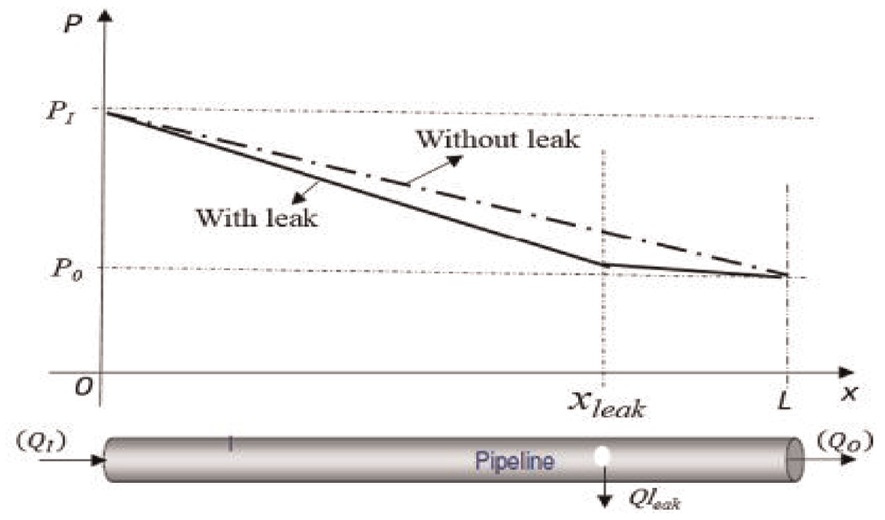
Image showing the location of gradient intersection leaks. 115
The cross-correlation algorithm has several problems associated with it, including the means of selecting the correct time window to allow the cross-correlation function to have an obvious peak value. During a leak, changes in flow rates occur that can be detected using flow meters, and ultrasound scans reflect changes in the pressure wave because of alterations in sound velocity. 115 Noise loggers used for pinpointing leaks are not always economically and technically viable. A correlation function was used to assess a leak and provide data concerning the delay between two signals. Using LeakFinderRT, the time delay (τ max) was used to find the peak cross-correlation automatically, and the time delay between two noise signals was related to the leakage site using equation (11).
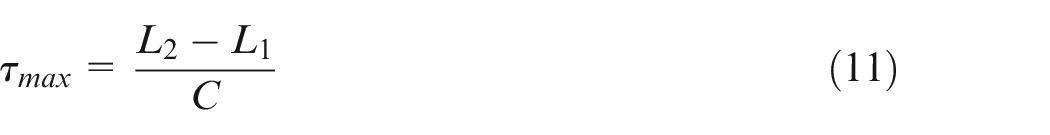
The leak position relative to point 1 was determined using equation (12).
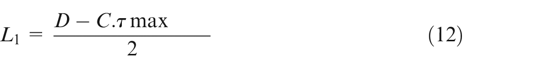
Where
In their study, Gao et al. investigated leaks by measuring vibration and acoustic signals acquired using hydrophones and accelerometers at two access points of a suspected leak. A leak noise correlator was used to process sensor information for determining the cross-correlation function of the signal to an operator. Figure 14 shows a conventional method of measuring a water leak in a buried water pipe and access points where sensors can be attached to detect distances (
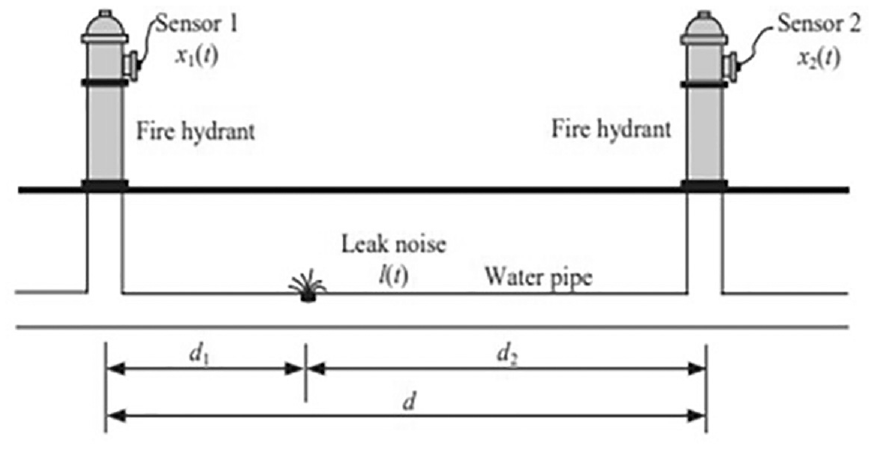
Tubing layout with one leakage and two sensors. 120
Eddy current techniques are typical methods for inspecting steam generator tubes. In one study, intergranular SCC was detected in the expanded tube connection area of the top of the tube sheet and tube support plate. Both axial and circumferential defects were detected using the eddy current array probe. To detect circumferential defects, the transmitter coils were S1 and S2 and the receiver spools have been replaced with R4 and R5. To continue measurement, the transmitters and receivers were switched. Axial defects required two other measurements: the transmission of the signal with the coil T1 and the signal received with coils R1 and R2. Calculations required for determining the critical crack size were provided and the existing failure stresses were based on the hoop and flow stresses. 114
It was found in one study that factors such as leakage values, air consumption, and compressed air system characteristics could be determined based on indirect flow rate measurements. Depending on the time intervals, pressure drop ratios helped indirectly to determine compressed air leakage. Temperature must also be considered when the internal pressure rapidly decreases and this solution is best applied in industrial compressed air piping systems. 121 This research analyzed the primary phases of leak detection and localization systems and noted the complex nature of having reliable leak detection tools. The next stage involves developing a real-time monitoring system capable of detecting large and small leaks. The proposed methods are based on identifying blind systems. Nonetheless, it should be recognized that the implementation of methods in large WDNs is extremely challenging.
Research challenges in the existing literature
The main contribution would be determining leakage quantification using an empirical relationship based on fracture toughness versus initiation crack versus leakage. Moreover, the overall methodology will also consider fracture toughness reduction due to environmental conditions and corrosion conditions.
Conclusion
The nature of pipe degradation within a system is multifaceted because of the various chemical and physical variables. Nonetheless, this research has attempted to highlight the most salient variables capable of having an adverse impact on network longevity and fluid delivery. Network deterioration can be attributed to a range of physical mechanisms, including external and internal variables that have an impact on pressure and alter the structural properties of pipes. Nonetheless, the data show that hydrogen embrittlement and corrosion are the key degradation routes for metal pipes.
The data acquired for two-phase gas–liquid fluids operating under different circumstances were also useful when trying to understand leakages found in water pipe networks. In addition, when modeling and specific site data are synergized, this should prove useful to stakeholders, such as maintenance crews, others developing risk assessments, and those involved in CFD-based approaches, by reducing leaks through early detection.
This research highlights the need for a leak management strategy that accounts for pipeline attributes such as network location, design requirements, operational variables, and internal and external pipe features. For example, design requirements and pipeline locations are salient features for municipal water networks because network failure is linked with operational features, environmental conditions, and geometric variables. Pipe degradation is more likely to occur when these factors are neglected, resulting in network degradation.
Pipe integrity is significantly affected when exposed to hydrogen because of sulfide stress cracking and stress-oriented-induced cracking, which can eventually lead to failure. Degradation of this nature becomes more likely when factors linked to temperature, material attributes, and a combination of HEDE require networks of pipes to operate outside their design specifications.
This research has investigated the key factors linked to pipeline leakages and provided a review of LLMs and LDMs, as well as their advantages and disadvantages. Moreover, this research focused on pipes and joints and the impact of degradation on their performance. Although this research has responded to the academic gap it set out to fill, future works could place a greater emphasis on variables such as pressure flow, the fracture volume of intel gas, and temperature. Moreover, emerging technologies could also be used for detection purposes, including the Internet of Things, digital twins, and artificial intelligence. Emerging technologies have the potential to play a significant role alongside existing methods when monitoring in real time and providing leak data, which would facilitate more rapid decision making.
The empirical data show that fracture toughness is lowered as flaw depth increases – a correlation also reiterated in a SENT test using CTOD. However, there are considerably fewer data available on simulated pH solutions and how they affect networks of metal pipes. Moreover, at times, the available literature proved to be of very limited use because researchers used artificial soils which did not reflect the properties of soils found naturally. Although the effects of hydrogen and corrosion were documented, these studies did not perform toughness testing.
Data were used to generate statistical trends for leaks and critical crack lengths before applying a distribution for crack morphology variables that described defects with multiple orientations. Using the Monte Carlo simulation technique, the failure probability was determined in the presence and absence of a safety factor. After synergizing the data, the results were aligned using a Weibull distribution for the critical crack size and leakage rate. The main benefit of this computation was the ability to determine several crack types for these distributions. Based on the results, it is possible to conclude that the crack morphology parameter affected the leakage rate in a highly scattered way. Moreover, in terms of mechanical attributes, the ultimate yield strength was not as useful when compared with fracture toughness. However, since the results were based on the Henry–Fauske model, they have a weakness in terms of two-phase physics, indicating that the leak rate model could be improved further.
The available literature tends to emphasize corrosion velocity, crack progression, and mechanisms from a material context. However, there are many fewer data available on the effect of the fracture toughness of pipe materials. This suggests there are no data that link crack depth, toughness, and rates of leakage. This research has attempted to fill this academic gap by highlighting salient investigations and assessing LLMs and LDMs and their advantages and disadvantages. Moreover, it has provided data on the effects of corrosion on the fracture toughness of cast iron and the link between surface crack depth, toughness, and possible leakage amounts.
Footnotes
Declaration of conflicting interests
The author(s) declared no potential conflicts of interest with respect to the research, authorship, and/or publication of this article.
Funding
The author(s) received no financial support for the research, authorship, and/or publication of this article.