
Abstract
As the demands of materials in practical applications become more sophisticated, multiple technology streams have moved towards a smarter future, incorporating monitoring techniques to validate safety and performance. Optical fiber sensors offer a route to embedded sensing technology within new composite materials, but an understanding of resulting modifications to structural performance following inclusion requires assessment. This work studies three optical fibers (125 μm and 89 μm diameter with dual-layer acrylate coating and 80 μm diameter with polyimide coating) embedded in the composite material. Optical fiber placement and the effects of sensor orientation relative to fiber reinforcement plies, weave configurations, and stacking order considerations under varied load applications are considered and discussed. Empirical results on the effects of fiber coating composition and thickness on composite material samples were collected under flexural and tensile loading. With the aid of non-contact acoustic emissions monitoring, the effects of interfacial interaction between embedded sensors and surrounding composite materials have been assessed compared to elastic wave responses. This considered physical phenomena to map and assess the effects of introducing this structural discontinuity on these materials’ mechanical testing and capability. In doing so, this study adds to a gap in the existing literature by investigating the effects of the multiple variables for fiber sensor embedment in practical applications to move towards smarter material solutions.
Keywords
Introduction
Multiple technology streams have moved towards a smarter future, incorporating monitoring techniques to validate safety and performance. The fiber optic sensors offer a route to embedded sensing technology within new composite materials, but an understanding of resulting modifications to structural performance following inclusion requires assessment. Therefore, the empirical results on fiber coating composition and thickness effects on composite material specimens were collected under flexural and tensile loading. With the aid of non-contact acoustic emissions (AE) monitoring, the effects of interfacial interaction between embedded sensors and surrounding composite materials have been assessed compared to elastic wave responses. This considered physical phenomena to map and assess the effects of introducing this structural discontinuity on these materials’ mechanical testing and capability. Doing so adds to a gap in the existing literature by investigating the effects of the multiple variables for fiber sensor embedment in practical applications to move towards more intelligent material solutions.
Increased production and further use of composite materials in oilfield applications have brought about the foremost consideration of intelligent structures for sensing and monitoring applications.1,2 Fiber optic sensors were excellent candidates for non-destructive evaluation techniques, detecting possible damage, and measuring mechanical properties of pipework. 3 The implementation of these sensors provided significant enhancement in both industry and academia in evaluating mechanical structures during installation, fabrication, and product lifetime. The embedment of fiber optics towards composite material poses difficulties as the hist material’s mechanical performance can degrade, increasing the stress concentrations, probability failure, and the overall detrimentally impact the condition of the composite and fiber optic at the interface.2–7 The fiber-reinforced composites are the revolutionizing idea towards designing high-performance material for the oil and gas industry due to their enhanced strength and superior corrosion properties, heat resistance properties, and sufficient flexibility.8–10 Having said that, several considerations need to be conducted when applying embedded fiber optics for structural health monitoring. Sensor integration into the composite material matrix has been shown to be beneficial for assessing the overall integrity of the structural composite. 11 There are many ways and considerations for the successful integration of fiber optics into the composite material. This would relate to the embedment process of marriage without compromising the composite matrix. This would result in thermal and mechanical stresses, damaging the sensor or possibly altering its performance. It is, for this reason, essential to determine how the sensors would act upon embedding into the composite material and analyze the survivability of the sensor over long periods of use. 12 While fiber optic sensors brought many benefits towards material and structural monitoring of composites, the sensor poses challenges like improper treatment, which may lead to a short sensor. 13
AE monitoring was an instrumental technology for distinguishing material integrity issues such as a fracture or even fracture onset indicative of various wear and damage mechanisms.14,15 For these reasons, AE monitoring was used to distinguish whether the fiber optic has 1) fractured, 2) severe wear mechanisms/damage, or 3) very low to minor wear/damage. AE signal phenomena’s increased level and duration correlated with increased damage mechanisms and load conditions. 16 Using AE to monitor such changes can be used as a specific tool that enabled another view to investigate which composite structure was most optimal for embedment with fiber optic sensing. The type of sensor used was more applicable to an industry where a passive mode was used as opposed to a continuous one. A continuous mode was significant in recording large amounts of information albeit not targeted to a specific physical phenomenon where it was challenging to find the “nuggets of interest.” A single USB node was used because the set-up only allows a single sensor application with a protective housing. The key AE signal features of interest were “counts” and “amplitude,” displaying different findings when scrutinizing the specimens.
With a large infrastructure of pipelines, lack of monitoring, integrity concerns, and the intention to reduce maintenance costs grabbed the attention of applying needed solutions. With this aspect in mind, conducting specific research helped understand, improve, and develop a wide range of measurement parameters that range from mechanical deformation to temperature, corrosion, pressure, fluid flow characteristics, and structural integrity. One of the main issues was the fiber optic sensors affecting the mechanical properties and the composite material thermal properties of which the sensors were embedded. If not embedded effectively, it was known that damage could occur, hindering the operational performance of the material and sensor as a monitoring device. In addition, the longevity of the material and sensor was crucial for industrial applications. The effects of embedding the fiber optic technology with the composite material have to be understood; determining the long-term embedded fiber optic technology on the composite material needs to be fully understood to determine the long-term impact on material properties. 17 This was because diminished material properties, from embedding the fiber optic technology, significantly reduce the lifetime of the monitoring device and ultimately reduce the possibility of this technology being taken up and applied by industry.
Fiber optic-based sensor technology offers a significant benefit when embedded into materials; in that, they enable the measurement of internal strain distribution in real-time. An additional benefit from embedding this technology into materials, such as composite materials, was that fiber optic-based sensors could be effectively protected from the environment. This opens up several opportunities and can lead to this technology being applied to various temperature, strain, and pressure applications. Some of these applications include real-time subsea monitoring systems for pipelines or risers, 18 downhole monitoring, 19 and pressure vessels. 20 For an embedded fiber optic-based sensor to be accurate, there is a need to have an equivalent and sufficient transfer of strain between the host material and the fiber optic along the entire length of the marriage. This can enable the embedded fiber to act as a crack initiator, leading to the untimely failure of the structure. 21 As modern structures move towards more substantial and lighter materials, it paved the way for smarter material applications. Failure modes presented in the composite material can be challenging to detect, and the introduction of fiber optics can present discrete structural implications. Using acoustic emission analysis, this work determines the structural properties of fiber optic embedded composite materials that have undergone tensile and flexure material testing.
The mechanical tests measuring the elastic and strength properties of the composite laminate with and without the fiber optic embedment were performed, assessing the mechanical properties at the interface level and towards composite performance. The test was used to reveal the bonding quality between the embedded fiber optic sensor and composite material in which the tensile and flexural testing determined the elastic properties and strength. The testing was performed at room temperature and humidity. Limitation towards laminated composite material features was their tendency for matrix cracking, which can be within the plies and resulting in interlaminar cracking and delamination. Therefore, destructive evaluation techniques have been set to detect the characteristic changes towards the embedment process. The specimens were made for the composites with and without embedment of the fiber optic. Differences towards the weave resulted in the change of spacing in the composite, resulting in varied shear strength in each direction. By theoretical means, it should change the shear behavior of the composites at different orientations.
Industrial usage of advanced material seen in harsh environments and the need for remote condition monitoring brought attention to the durability, reliability, and sustainability of sensing technologies and how they would perform when fully integrated, offering the goal of in-situ assessments and future integrity pipelines. Advanced composites are ideal for oil, gas, and water industries following their benefits, offering better long-term use and application in an acidic and alkaline environment and to reduce overall maintenance costs under harsh environments and remoteness. Therefore, the paper investigates more into advanced material technologies and how such materials would affect the embedded sensor over time. This includes matrix with different plies and layups, embedment for sensors into advanced materials, and working fatigue during industrial application.
Experimental technique
Fabrication technique for the optical fiber embedded composite material
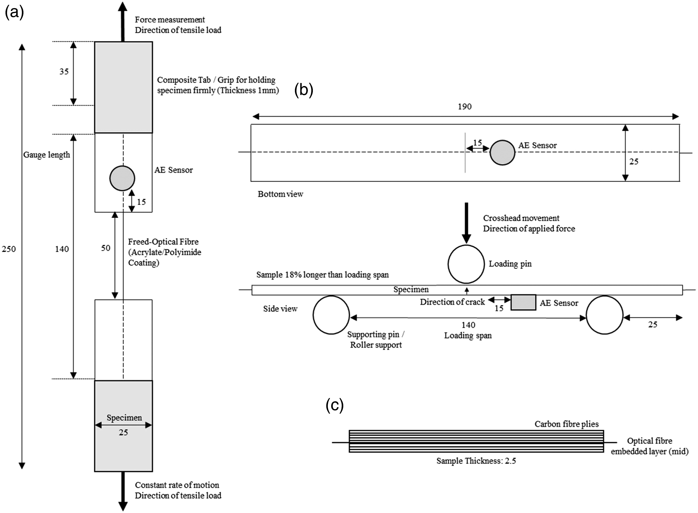
To fabricate the composite material, the hand layup method was used in accordance with Ref. 22. The hand layup method is one of the most commonly used fabrication processes adopted when conducting laboratory-based composite manufacturing. Samples were manufactured at room temperature (21.0°C), fixing carbon fiber layers one at a time with EL2 epoxy laminating resin at a ratio of 100 parts of resin to 30 parts of AT30 slow hardener in between each of the plies. The fabricated samples were 102 mm long and 26 mm wide. The samples used for flexural testing were 2.5 mm thick. The samples used for tensile testing were 250 mm long, 25 mm wide, and 2.5 mm thick. Samples consisted of 8 layers of ply sheet for 2,2 plain-woven materials consisting of 3K tows of Pyrofil® TR30S fibers, and 6 layers of ply sheet for ±45° biaxial non-crimp fabric material consisting of 3K tows of Pyrofil® TR30S fibers. Carbon fiber weaves and formulated epoxy were sourced from Easy Composites Ltd. The consolidated fiber volume ratios of each arrangement were estimated at 80% for the twill weave arrangement and 72% for the biaxial arrangement, not accounting for packing arrangement and efficiency of fiber tows. However, it was difficult to empirically verify due to a lack of suitable characterization equipment. The fiber elastic modulus was nominally similar, but samples were set to achieve a similar thickness and resulting volume. The higher fabric weight and resulting thickness of biaxial sheets meant that consolidated under vacuum assisted curing, only 6 plies could be used, leading to a potential reduction in elastic modulus. The reduction in fiber volume ratio by 8% should have led to a similar reduction in elastic moduli between the two composites samples.
The optical fiber was embedded in between the two middle plies of each stacking order across the axis of symmetry. The optical fiber was cut at 152.4 mm, leaving 51 mm exposed at the gauge length. The procedure was to ensure that the embedded optical fiber was pulled uniformly during tensile testing. During the fabrication process, three different types of optical fiber were used: 125 μm with coating diameter of 241.4 μm, 89 μm with coating diameter of 169.6 μm dual-layer acrylate coating with germanium-doped core composition, and 80 μm with coating diameter of 103.1 μm polyimide coating with germanium-doped core composition.
Coating optical fibers has a significant effect on the life of a sensor embedded in a composite laminate and will hugely impact the chemistry relative in order for the resin to be uniformly associated with the composite. 23 The primary role of a coating is to mechanically protect the optical waveguide from glass surface contact and breaks, ensuring long-term mechanical reliability. 24 Coatings are also applied for high-temperature resistance. Polyimide coating is ideal to acquire high-temperature resistance, and the coating will withstand the operating temperature up to 400°C or 300°C continuous, while conventional acrylate will deteriorate between 100°C and 250°C.
Composite sheets were stacked onto one another, forming layers of fabric, creating a strong matrix laminate structure for reinforcement. After the stacking sequence, the test specimens are cured and shaped as to the desired specification for the testing. Hand layup was chosen and carried out manually after the test samples had been impregnated and stacked to the correct ply orientation. During the wet layup procedure, the material was left to cure at room temperature. The samples were cured based on manufacturing specifications that were left for 6 h with applied pressure and an addition of 8 h to fully solidify the samples in respect to the use of a slow resin chemical mixture. The curing time will enhance the formation of the chemical bonds and improve the diffusion of the mechanism at the optical fiber and resin interface. Due to circumstances of embedding the optical fiber in the composite material, the coated optical fibers will not withstand high temperatures; therefore, oven curing was not used. The composite manufacturing process used in this investigation undergoes several steps. These steps include: 1. Preparation of the desired fiber material for the composite. 2. Application of resin to impregnate preform. 3. Curing of resin to attain solidification of the matrix. 4. Finalizing the consolidation process of the composite material for end-use.
Geometrical orientation and placement of the optical fiber relative to the laminate plies were primary factors of concern to its influence on the material’s mechanical performance. The fiber orientation, strength, and stiffness of a composite depend entirely on the orientation sequence of respective plies. The property in the range of values is determined by the orientation of plies to the applied load and because the strength design requirement is the function of the applied load direction, ply orientation and ply sequence must be appropriately assigned. It is considered as the most crucial aspect since the proper selection of the ply orientation in the composite material is truly necessary for providing the structural efficiency design. The orientation of 0° plies is expected to react towards axial loads, ±45° plies are expected to reach shear loads, and 90° plies are expected to react to side loads. The direction of the orientation can be classified as the warp clock. The warp indicated the longitudinal fiber orientation of fabric and is depicted as the high strength direction. This is used to describe the direction of the fiber orientation. 90° to 0° was the orientation of the fabric across the composite laminates.
Tensile and flexural testing of the optical fiber-embedded composite matrix
A universal testing system (3369 Series; Instron, UK) with accompanying software (Blue Hill; Instron, UK) was used for the tensile and flexural material testing. In all testing variations, crosshead displacement was set to a fixed rate of 10 mm/min. Additional control measures were utilized for the flexural test with a load and extension limit of 5 kN and 20 mm, respectively. The system was calibrated to BS 1610-1:1992 (85) and traceable to the International System of Units (SI) through the local National Metrological Institute (NMI). The calibration verification (ISO/IEC 17025) was accredited by UCAS calibration.
The experimental procedures were carried out according to the ASTM D3039/D3039M standard test method for tensile properties of polymer matrix composite materials and D7264/D7264M standard test method for flexural properties of the polymer matrix composite material for guidelines and test procedures. The mechanical testing in this study was performed to measure the strength and elastic properties of the composite laminates with the embedment of the optical fiber and assess the mechanical properties at the interface level and composite performance. The tests conducted revealed the bonding quality between the composite material and the optical fiber sensor embedded. Three repeats of each test were conducted to obtain mean averages.
The testing was divided into two fundamental types: 1. 2. Schematic diagrams of (a) a tensile test specimen as per ASTM D3039 standards, (b) a three-point flexural test specimen as per ASTM 7264 standards, and (c) the composite sandwich structure embedded optical fiber. (All dimensions are in mm.)
Optical microscopy (Flash 200 Smartscope; OGP, Ltd) was conducted to obtain optical micrographs of the specimens to image the resulting delamination from the mechanical testing.
Set-up for acoustic emission calibration tests
Specification of the acoustic emission sensor.
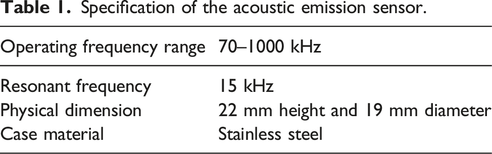
The sensor was clamped onto the load. The acoustic emission data were used to identify the failure of the optical fiber embedded within the composite material. The graphs produced from the Instron UTC, detailed in the section Tensile and Flexural Testing of the Optical Fiber-Embedded Composite Matrix, were compared to the occurrences observed during acoustic emission analysis. During the material testing, a significant spike in captured noise would associate itself with a failure point or phenomena within the material interfaces.
Calibration tests
The Hsu-Nielson pencil break calibration method 25 was utilized to test sensor saturation and surface compliance prior to testing. The first calibration was taken as a reference and normalized based on similar points during the calibration. The calibration pencil fracture was carried out 5 times, and a mean average was taken from the results for normalizing the signal. If the pencil break tests produced significant variance, the set-up would be inspected and modified to ensure that consistent results are obtained for comparison.
Results and discussion
Flexural testing
A flexural test was used to determine the mechanical properties of the composite material laminate and the resin combined. Tension underneath the test samples would force the composite fiber to fail/delaminate and therefore could be used to determine the differences in the mechanical behavior of carbon composites with the embedded optical fiber. Progressive delamination was expected to radiate from the point of impact through the geometry thickness connected to the interlaminar and shear cracks and was caused by an impact-induced flexural deformation.26,27 All specimens had the same span length making it possible to have an accurate result to load/displacement relationships obtained from the samples, and the results gathered supported a good correlation of failure mechanisms. This uniform approach ensured that the samples endured both high and low stresses at the central axis where the load was applied. The top of the specimen was subjected to compressive stress, and the bottom of the specimen experienced tensile stress. The stress will have caused an increment to the focal ratio degradation (FRD), which is considered a negative aspect for optical systems that depend on the sensitivity of the focal ratio of the optical fiber exit.
Mean average results for each specimen following flexural testing.
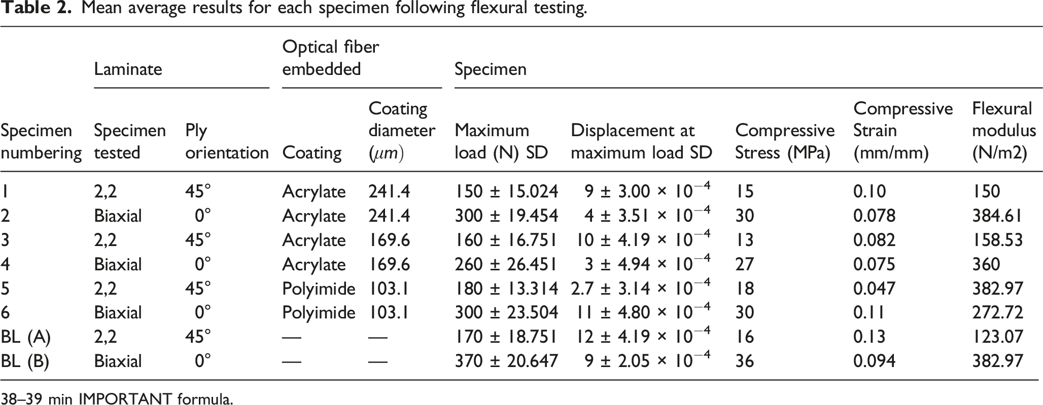
38–39 min IMPORTANT formula.
The composite fiber orientation, strength, and stiffness of a composite were dependent on the orientation sequence of the respective plies based on the function of applied load in a specific direction, ply orientation, and ply sequence. Proper selection of the ply orientation in the fabrication of composite materials is truly necessary to provide the optimal structural efficiency design. The specimens detailed in Table 2 define the variation in samples in terms of laminate type, with fiber embedment, fiber type, coating diameter, and the dimension of test samples.
Yielding was observed faster with the ±45° 2,2 specimens (specimen 1 and specimen 3) and required lower maximum loads for failure, with 150 N and 160 N being recorded. This maximum loading, until failure, was half of that compared to the biaxial 0° specimens (specimen 2 and specimen 4), which gave rise to maximum loads of 260 N and 300 N. It is worth noting here though, that the biaxial 0° specimens (specimen 2 and specimen 4) had much smaller displacements at the maximum loading due to sample thickness and orientation the brittleness influenced and the amount of stress being applied during compression, which resulted in reaching highest compressive strength.
The next set of results displayed in Figure 2 further demonstrates the strength of the biaxial 0° weave orientation configuration (specimen 2) compared with 2,2 Twill composites with 45° weave orientation (specimen 1). With this comparison, specimen 2 AE amplitude obtained a max of 80 dB whereas specimen 1 obtained 80 dB at the same time, and instead of settling and degrading, it started to rise and remain high at 100 dB, consistent with optical fiber material fracture. Specimen 2 AE response is somewhat superior to specimen 4 in terms of resistance to material degradation. The diameter was consistent for both specimens at 241.4 µm. Amplitude (dB) against time (s) comparing specimen’s average 1 (ply orientation of 45°) and 2 (ply orientation of 0°).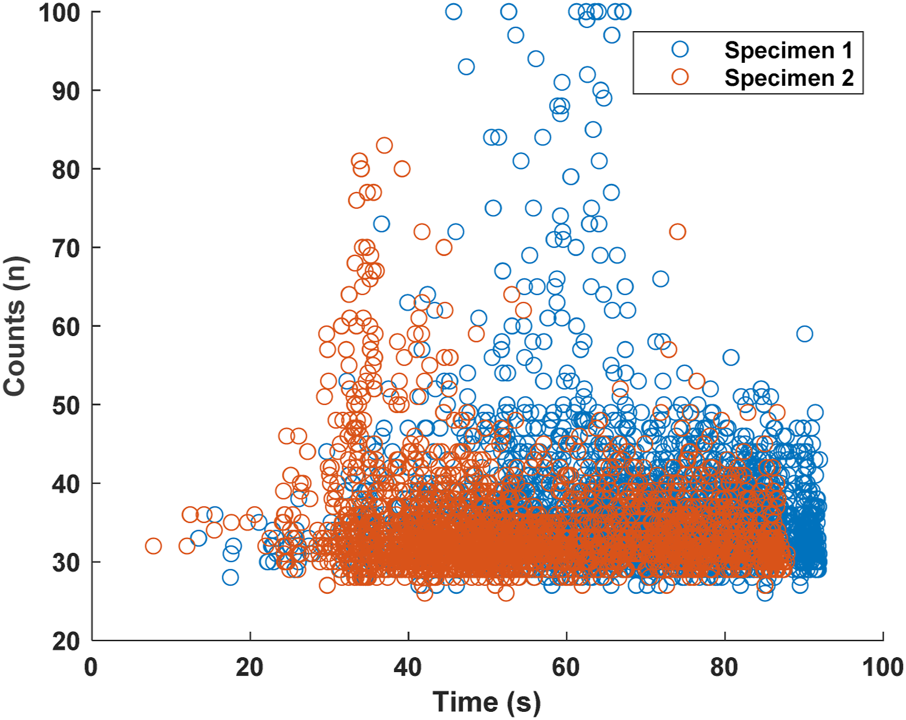
Figure 3 shows very encouraging results where the counts remain very low for specimen 2 and much higher for specimen 1. This again is consistent with the results displayed in Figure 2. The AE counts are linked to the duration of significant AE phenomena, whereas the AE amplitude is significant of a burst energy event. There should always be a correlation between the two where each provides a different parameter data view giving a multi-dimensional picture as opposed to a singular one. Counts (n) against time (sec) comparing specimen’s average 1 (ply orientation of 45°) and 2 (ply orientation of 0°).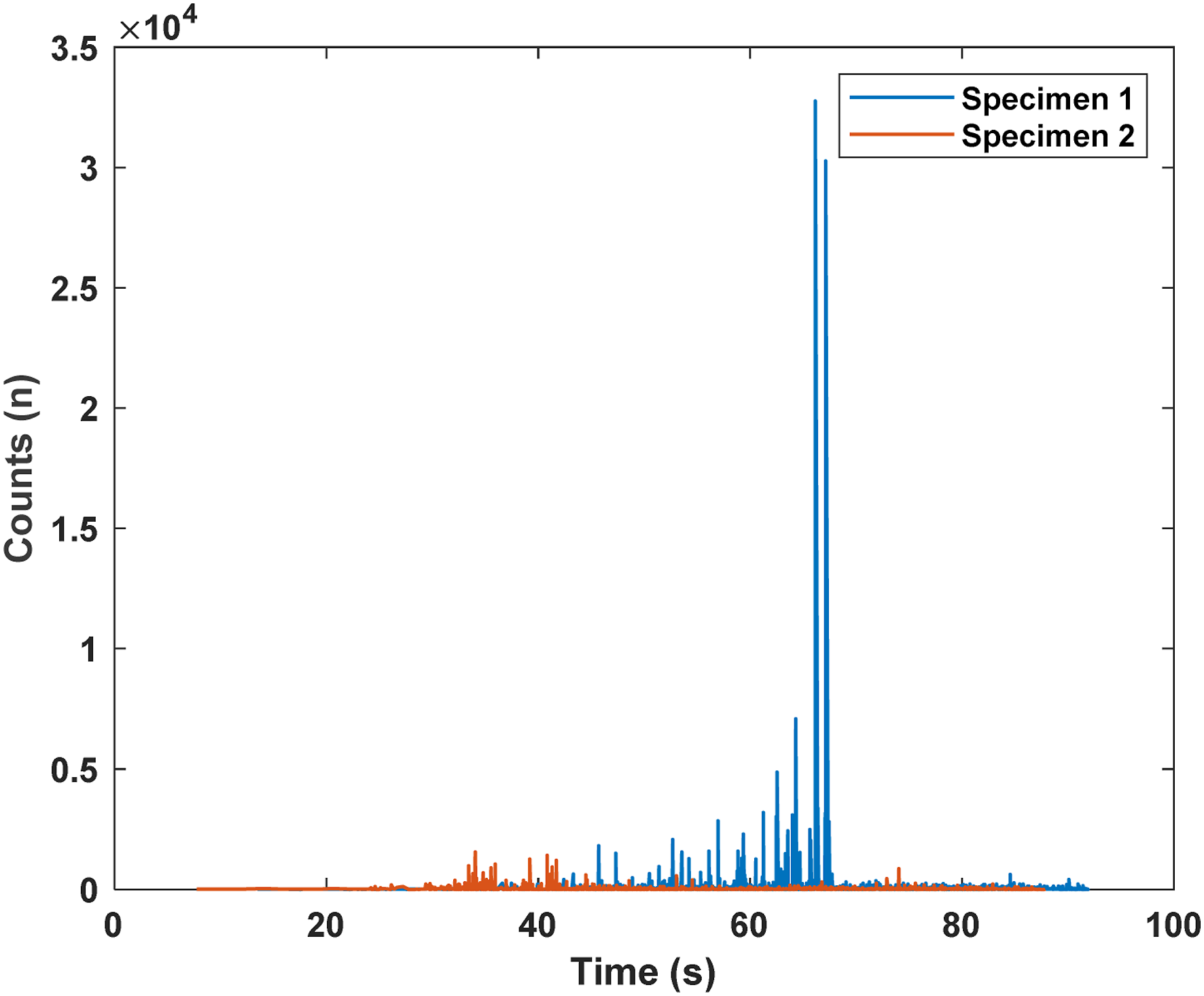
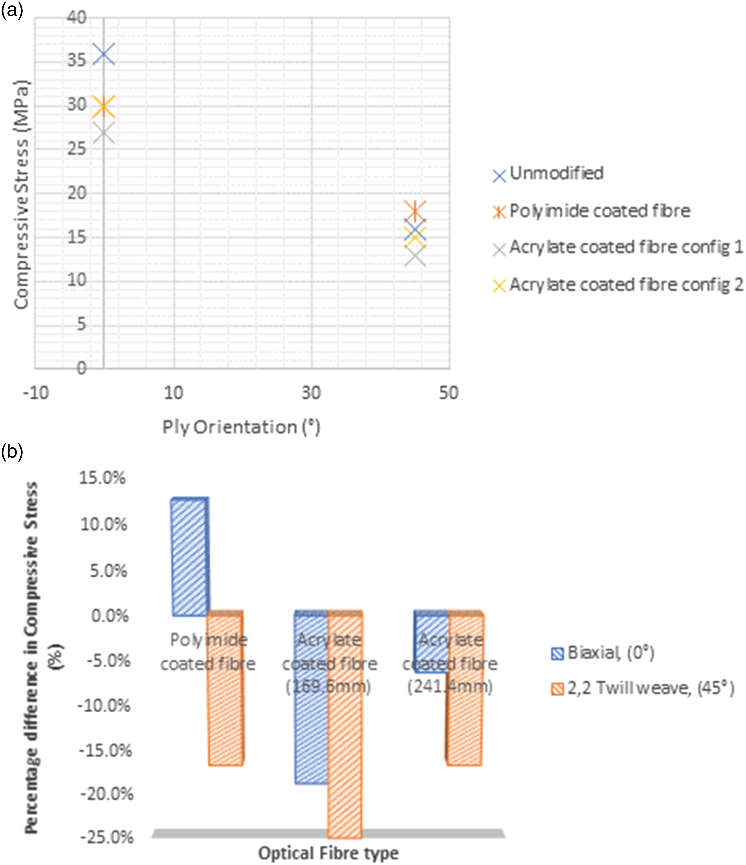
Figure 4 displays the mechanical data obtained from the Instron load platform. These mechanical load data are correlated with each of the AE information displayed from Figures 2 through to 5. It can be noted from Figure 4 that both specimen 2 and specimen 4 obtained a much higher stress/strain relationship than specimen 1. This one is a further evidence that biaxial 0° weave orientation is better suited for embedded optical fiber applications than the 2,2 Twill composite with 45° weave orientation material configuration. Mean load (N) against mean extension (mm) comparing specimen average 1(ply orientation of 45°), 2, and 4 (both ply orientation of 0°). (a) Mean average compressive stress (MPa) against ply orientation (°) comparing groups of fiber orientations and weave types. (b) Mean average percentage difference in compressive stress (%) against optical fiber type for biaxial (0°) and 2,2 (45°) weave orientation.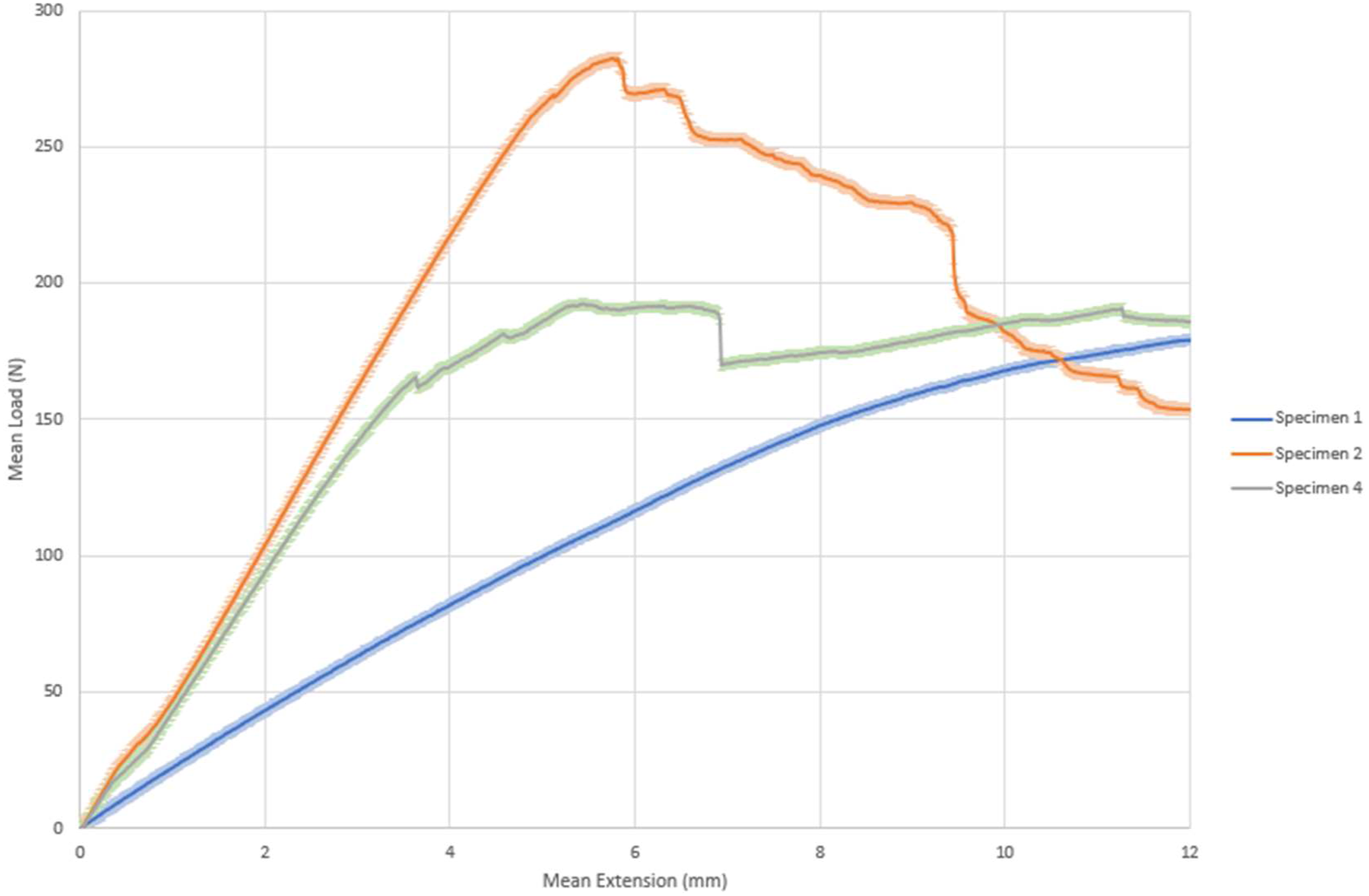
The true mechanical data from unmodified carbon fiber specimens BL (A) and BL (B) in Table 2 with maximum load of 170 N against 370 N, respectively, shows that the biaxial sample was stronger than 2,2 because the maximum load is higher. Compressive stress is higher, and compressive strain across 2,2 is higher than the biaxial one.
The presence of coating from the optical fiber, compressive strain increased in all cases. In a 2,2, the issue of embedding the optical fiber, maximum load across specimen (1,3,5) presented little to no change in the maximum load as compared to specimen BL (A). The effect of putting a fiber optic with the compressive stress is significant. The maximum load average of a biaxial unmodified composite material specimen BL (B) resulted to 370N, maximum load, compressive stress, and strain for the specimens (2,4 and 6) dropped.
In comparison, polyimide in a biaxial configuration helps with the load-bearing capability, and the compressive strain was better from the polyimide in a 2,2. Whereas for an acrylate-coated fiber, it fitted more in line with the 2,2 and biaxial unmodified carbon fiber in the sense that the changes were lower as varied coating diameters were introduced.
The compressive strain values of the acrylate embedded 2,2 decreased in terms of compressive strain capability from the 2,2 unmodified, whereas in specimen 5 with polyimide coating, there was a massive decrease in compressive strain capability. This suggests that 0° weave orientation is better in certain situations when compared to the 45° weave orientation, and the polyimide coating is detrimental in 0°; thus, compressive strain decreases massively. 0° ply orientation with an acrylate had a much lower effect in terms of the losses. The coating of fiber optics plays a vital role in terms of the massive difference. The coating of the fiber optic is potentially better in certain situations than others.
Knowing that the biaxial configuration is stronger but gives less ability for stretching, polyimide in a biaxial configuration increased the compressive strain average against the biaxial unmodified carbon fiber, whereas using an acrylate-coated fiber, the results are shown to have a dropped indifference.
This was studied between the acrylate with different coating diameters, and there were differences as lower coating diameter created lower compressive strain in a 2,2 compared to the material without optical fiber and bigger coating diameter. In terms of preserving compressive strain, a bigger coating diameter is preferential because it allows for better compression to the unmodified composite material for biaxial and 2,2.
The difference in the way that the 2,2 and the biaxial reacted is based on the strain reduction from the material perspective. In a biaxial weave, the polyimide had a better compressive stress and load-bearing structure compared to losses for compressive strain. Whereas the acrylate was less in both cases, the significant change in compressive strain was huge compared to the polyimide embedment.
In polyimide, the strain reduction from specimen 6 to BL (B) showed a huge percentile difference compared to specimen 1 and specimen BL (A). That would suggest 45° ply orientation when matched with an acrylate coating, the acrylate-coated fiber would be a better marriage than that of a polyimide coated fiber. Overall, an acrylate-coated fiber as opposed to optical fiber with polyimide-coated fiber in a 45° orientation showed to be better in preserving the material capabilities. Specimen 6, the polyimide-coated fiber improves the compressive strain, whilst an acrylate decreases the overall mechanical strength. With 0° ply orientation, polyimide was seen to perform better, and, as a result, it can be a load-bearing structure itself in a sense where the strain increased.
As seen from Figure 5(a), using conventional polyimide coating, there was an increase in flexural load-bearing capability in biaxial samples. However, there is a trade-off in strain from Figure 6(a). The opposite is true in 2,2 twill weave samples. The acrylate coating samples were more consistent, and more importantly, did not create load-bearing interactions. As a sensory component, they were helpful in not changing material properties with the interfacial interactions between the coatings and the resin for the material for having different behaviors based on different functional groups inside monomer groups used for the construction of the coatings. (a) Mean average compressive strain (mm/mm) against ply orientation (°) comparing groups of fiber orientations and weave types. (b) Mean average percentage difference in compressive strain (%) against optical fiber type for biaxial (0°) and 2,2 (45°) weave orientation.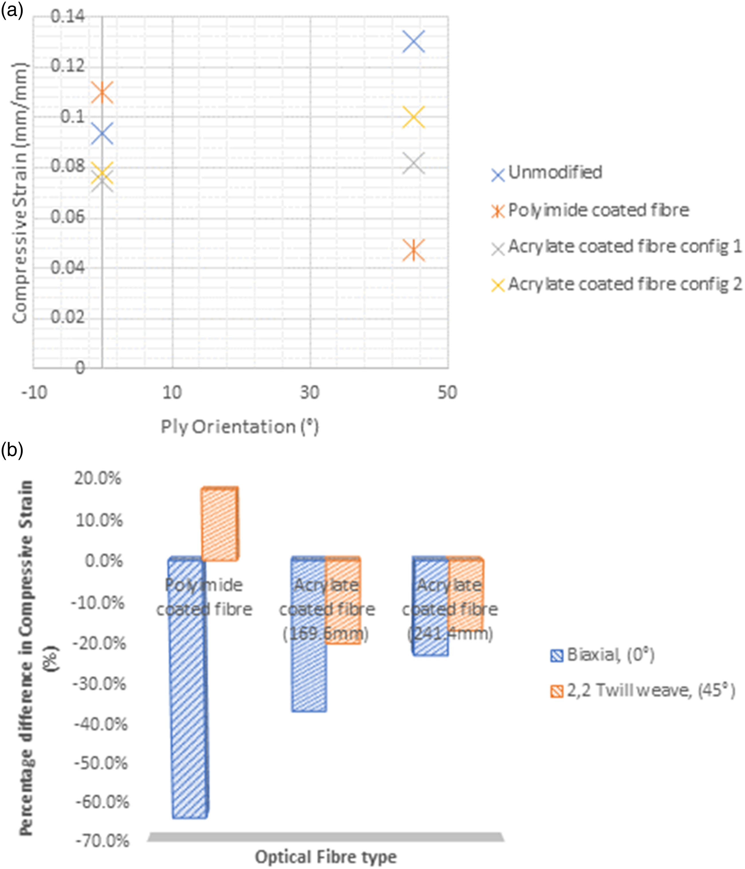
Investigating this further, the effect of coating thickness played a significant role in helping to arrest any degradation of material properties. The thicker coatings may have become more of a load-bearing element, but they immediately affect true material properties. This means that there is certainly an argument for exploration into the effects of coating thickness on the discontinuous effect of fiber sensor integration.
Moreover, the acrylate coatings offer a degree of consistency compared to the accepted polyimide coatings across multiple weave patterns. The percentile difference from the results in Figures 5(b) and 8(b) shows this clearly. We can say that with multiple weave, acrylate coatings offer a practical solution for embedding fibers in off-axis configuration
From Figure 7(b), the counts for the unmodified composite are much higher, but the events spread from the amplitude graph appear to be more stable in Figure 7(a). To that end, any signs of failure seem to be a more sustained issue in general. In comparison, all samples with embedded sensors have much higher amplitude spikes, likely stemming from the differences in material consistency. The fiber and the carbon fiber interact at different rates due to their material properties. However, evidence from the results shown in Table 2 suggests that 241.4 acrylate fiber had a lower mechanical issue with this than the 169.6 acrylate fiber and the polyimide from both data comparisons. (a) Comparison of AE events amplitude monitoring with variable configurations of biaxial weave samples under flexural loading. (b) Comparison of AE events counts monitoring with variable configurations of biaxial weave samples under flexural loading.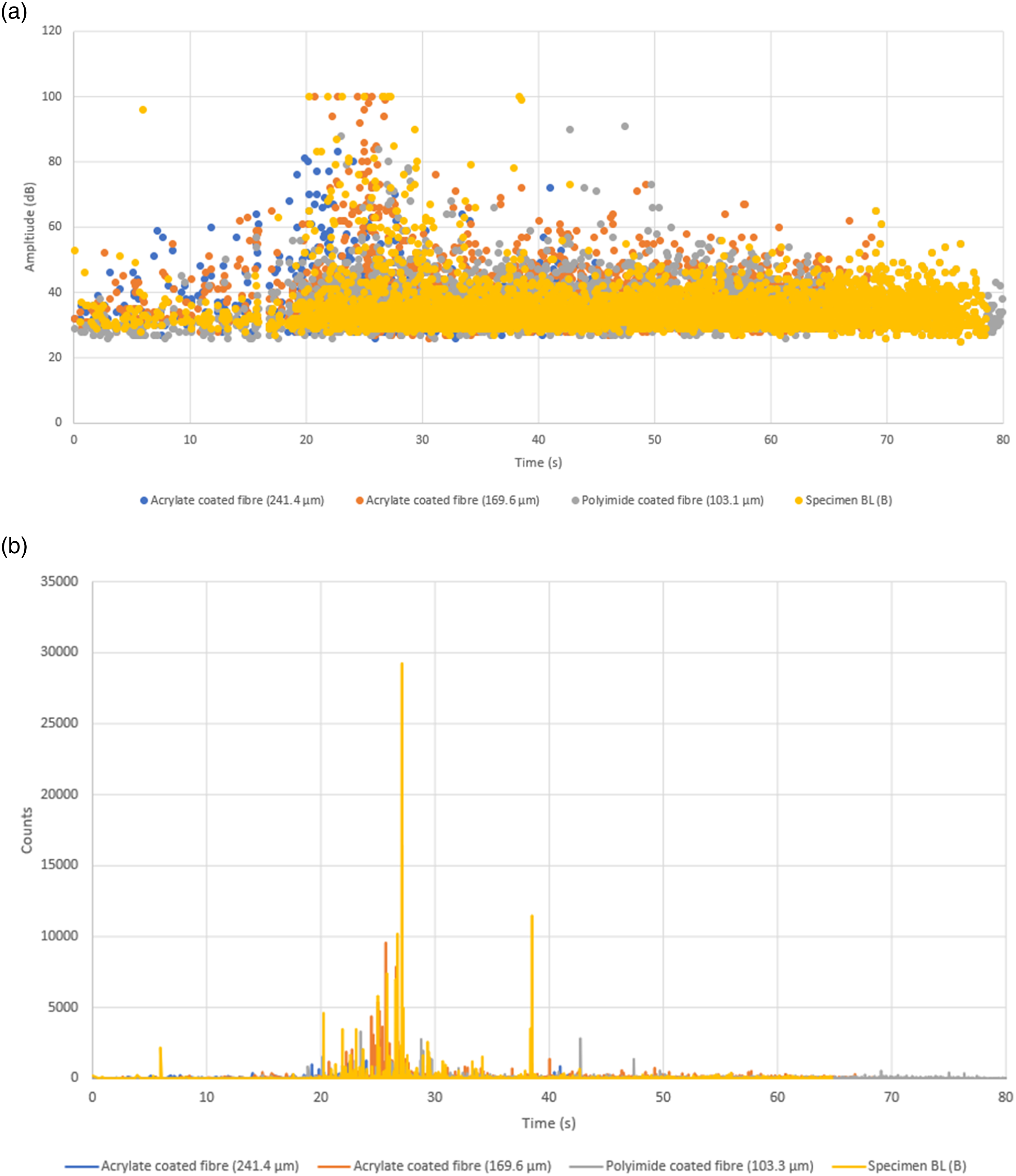
From Figures 8(a) and (b), across 2,2 twill weave data, 241.1 μm acrylate-coated fiber is the worst performer compared to 169.6 μm in comparison to the polyimide-coated fiber. Across the board, it is shown lower. In different situations, different thicknesses of acrylate fiber might be a more consistent option for not impacting baseline material properties while the polyimide fiber may have subjectively improved certain aspects of mechanical flexural behavior, and the acrylate-coated fiber had a completely different interaction during failure. This may seem obvious since acrylate polymer chains and polyimide chains are different in spacing and dipole orientation. (a) Comparison of AE events amplitude monitoring with variable configurations of 2,2 weave samples under flexural loading. (b) Comparison of AE events amplitude monitoring with variable configurations of 2,2 weave samples under flexural loading.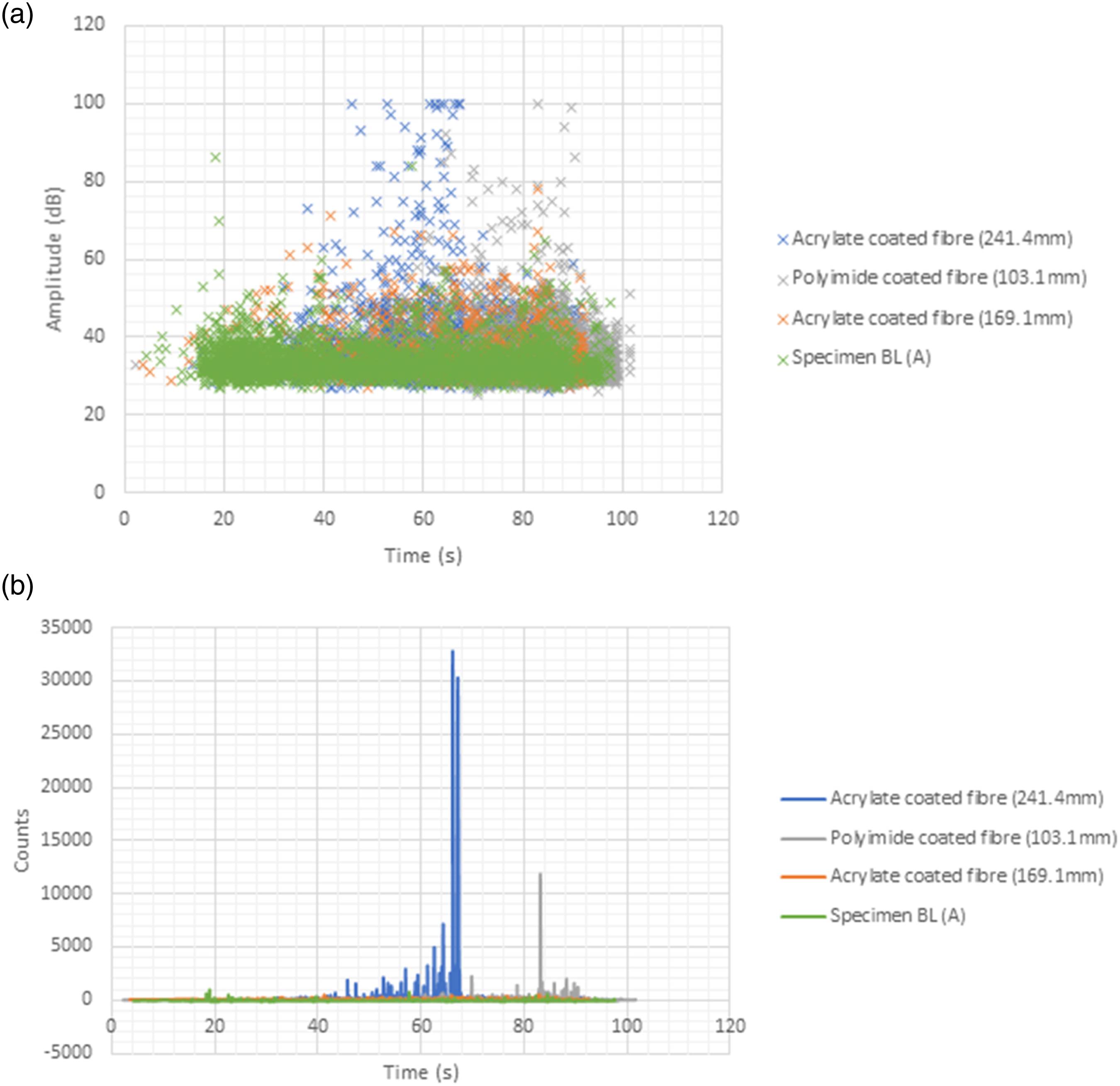
The embedment of fiber optic composites is expected to result in different failure mechanisms if it is embedded with different coatings. This is because the coating on the fiber acts as an interface between the composite and the fiber. In addition, the mechanical properties influence both the failure mode and the sensitivity of the fiber sensors. The delamination results from the embedded optical fiber acts as inclusion and induces local strain concentration to interact with the stress-induced and local strain field. It intensifies the amplitude of the stress and enhances the impact damage. Discontinuity in which the resin created an issue for a possible defect in the composite could lead to premature failure in the form of delamination. In certain situations, a polyimide embedment in this study showed that compressive stress is favoring reinforcement. Increasing coating sizes change the way discontinuity is introduced, as it changes the local volume ratio between matrix and discontinuity.
The proper selection of coating property will eventually help protect the cladding and the core from where the environment can be used in the embedment of fiber optics. Inappropriate choice of coatings can lead to severity of mechanical integrity embedded to the composite material that has been observed through the specimen experiencing coating deformation and early breakage.
Fiber thickness plays an equally important role in the effect of embedded sensors on mechanical loading, and, due to differences in interfacial interaction, there are merits to using different coatings and thicknesses for different applications. If the overall diameter of the optical fiber could be increased, the effect would be minimized, and there will be a lower loss in strength of the composite as the material properties of the optical fiber are stronger than epoxy. It is assumed that if the fibers were very closely spaced, it is not a serious issue as to what may cause delamination to the possible defect towards the resin pattern embedded.
Orientation and placement of the optical fiber placed in a composite material may cause a significant influence on the mechanical properties as the interfacial bond between the fiber and the matrix is stronger than the actual tensile strength of the fiber itself. The fiber optic’s coating property influenced the composite material’s mechanical integrity from the increased sequence of layers, resulting in tensile mechanical performance.
Optical microscopy
As shown in Figure 9, the cross-section showed delamination, matrix cracking, and optical fiber breakages occurring between the layers of the composite material embedded with the optical fibers. This is in agreement with Ref. 27. The delamination was caused by debonding of the composite plies because of the compressive force acting upon the specimen from the point of the load being applied. The highest amount of delamination and matrix cracking was observed to take place on the central axis of the specimen due to the force concentration being the highest at that point during the flexural testing. Optical micrographs showing the delamination in (a) specimen 1, 2,2 plain woven at 45° fabric orientation and (b) specimen 4, biaxial at 0° fabric orientation.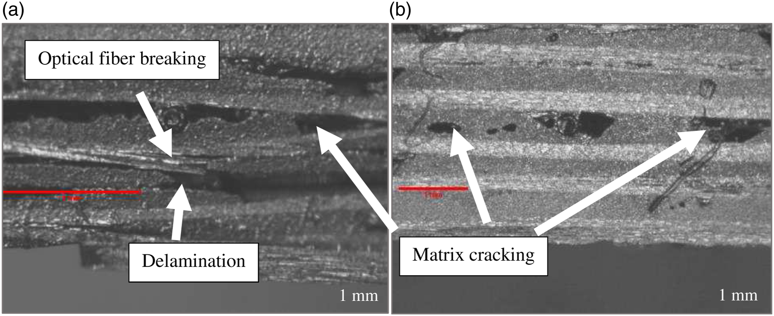
The response of the optical fiber embedded in the composite material and the failure that can occur is dependent on the placement and orientation. The strength and orientation of the material will affect the strain transferred to the optical fiber. The thickness of the coating and the resin property used will also impact the structural integrity. 28 The accumulation of microstructural damage mechanisms includes matrix crack, composite fiber breakage, delamination, and debonding, which will occur independently and be affected by the testing condition and material variables. 29 The presence of the optical fiber will have had an impact on the development of stress concentrations, and the orientation and placement of the optical fiber will have a significant influence on the mechanical properties. 26 Damage and failure occur by the propagation of a single microscopic crack, and the optical fiber will degrade the mechanical performance of its host material. This case will have negatively impacted the uniaxial tensile and compressive properties of the composite laminates. The coating of the optical fiber can provide an interphase material that can improve the survivability of the embedded optical fiber embedded. It should also be noted that the presence of the coating will affect the performance of various sensors. The presence of coatings can lead to a lower sensitivity since the coating serves as a buffer between the composite matrix and the optical fiber.
For a good coupling of the optical fiber to the carbon layers, the composite fabric orientation is an important aspect and has been shown to be an important factor when considering the structural integrity during flexural testing. The delamination can be an issue but is mainly related to the carbon layers orientation and degassing of the epoxy used.
Tensile testing
Mean average variation in samples resulted to its maximum load range for tensile.
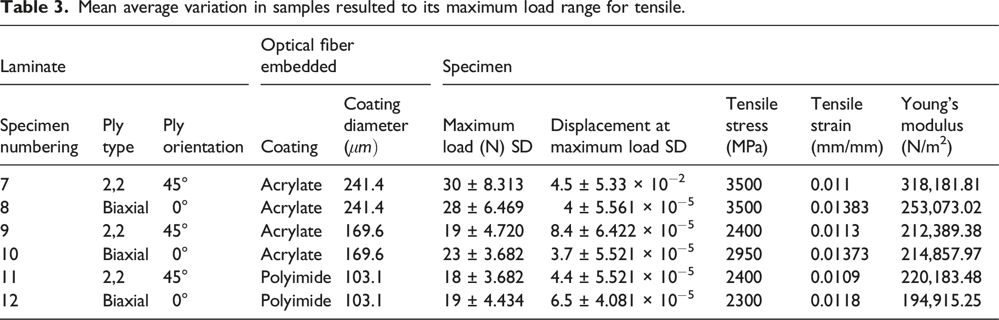
Whilst there was an expected change in elastic moduli between the two samples, with the loss in plie layers for the biaxial fiber leading to a reduction in tensile capability, results in Table 3 suggested that this was not the case with specific changes to coating polymer substrates and subsequent diameters, with some examples showing negligible change between the two types of woven pattern. This suggested that the woven patterns and epoxy arrangements played some part in the adhesion mechanisms between optical fiber coatings and surrounding carbon fiber reinforced structures.
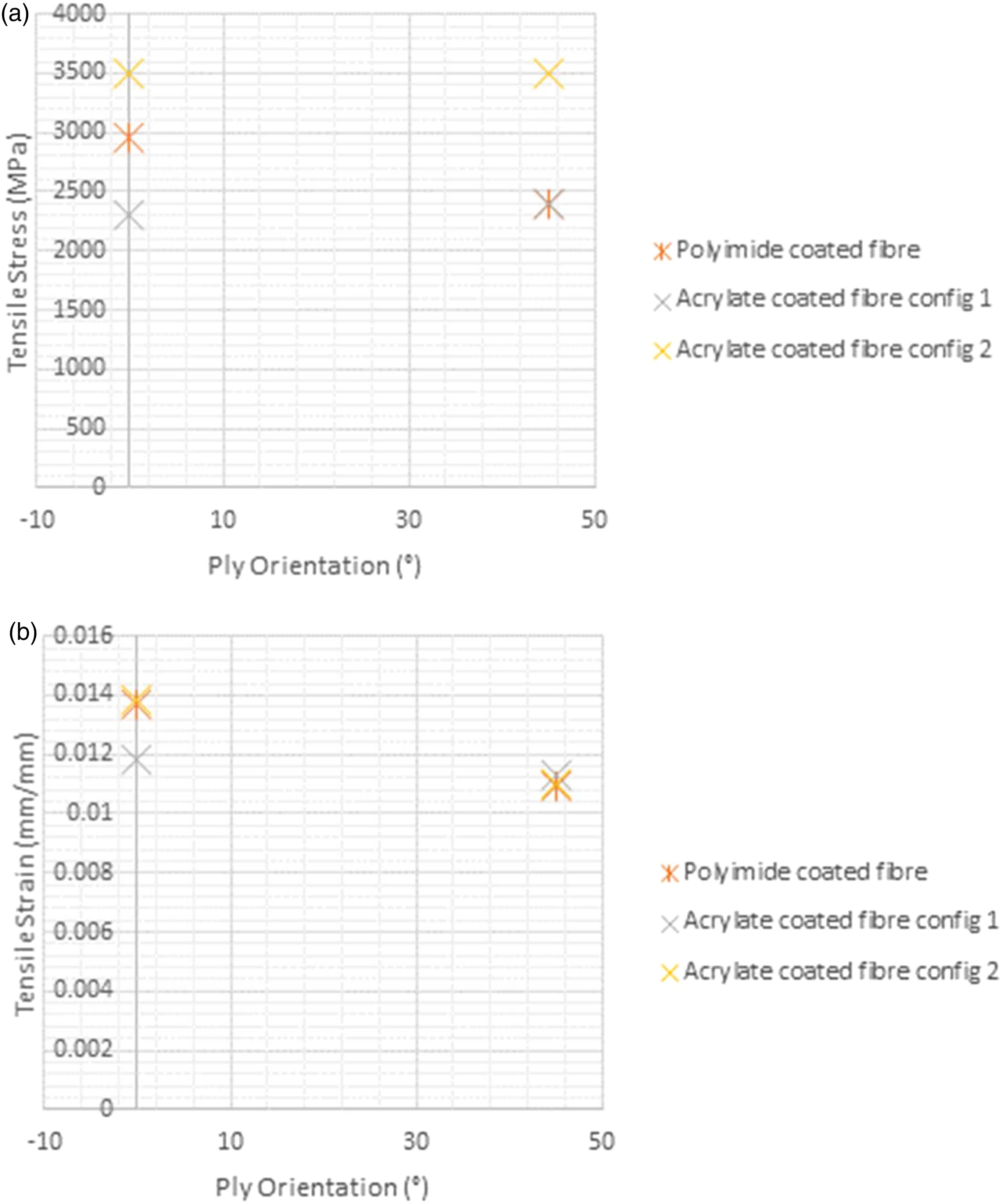
In comparing coating thickness, there was a distinct, noticeable trend in the effect of a thicker coating, with 241.4 μm coatings achieving a maximum load of approximately 30 N, and a similar sample tensile stress of 3500 MPa, with slight variation between the 2,2 twill weave and biaxial weave patterns. The thinner 169.6 μm acrylate coatings reported tensile stress for the twill weave and biaxial weaves of 2400 MPa and 2300 MPa, respectively; difference in the surface area had a pronounced effect on surface interactions between the epoxy matrix and coatings. This observation suggests a difference in the interfacial bonding between the optical fiber and the composite stronger than the optical fiber alone. Fibers were subjected to a shear interaction at interface points, leading to a slipping effect within the composite structures as optical fibers detach from their surrounding material. The approximately 42% unit of surface area increase between coating allowed for a larger wetted area of interaction with the composite material, leading to better adhesion at the expense of introducing a larger discontinuity within the material. This seemingly played a more significant role in tensile considerations due to the nature of loading compared to mixed interfacial loading experienced within the flexural samples. Shear force interaction was the dominant factor within this testing mode and was the most likely source of failure. Shearing of the coating of the optical fiber will result in a release from the composite embedment. The discontinuity from an embedded optical fiber may result in an elastic inclusion within the host material, causing possible stress concentrations related to the size and positioning inside the carbon composite. Physically during fabrication, the fiber could have caused the dislocation of carbon fiber weaves and physical changes to dimensions or resulting changes to fiber volume ratios. The physical distortion concerned can be an issue to the effect of coupling contributing to failure.
The issues of ingress and egress associated with the failure mode of optical fiber in the composite are solved by adopting soft silicone gel, which was used in combination with a Teflon tape in forming a buffer to the optical fiber near its exit point. This method consolidated the embedded optical fiber to have the strain uniformly transferred from its surroundings. This technique has been used previously. 28 The size of the optical fiber embedded is more significant than the composite structure. Therefore, it will have inevitably caused local distortion to the host material. By minimizing the diameter of the optical fiber, can eventually reduce the distortion in the composite. The optical fiber influences this mismatch of the size difference and the composite it is embedded into. The alignment for the optical fiber in respect to the composite reinforcement fibers will also influence the distortion, and, with smaller diameters of embedded optical fibers, will increase the overall strength of the composite. Also, with a smaller optical fiber embedded, this will reduce the resin-rich region surrounding the optical fiber.
However, the significant increase in adhesion surfaces of the acrylate fiber appears to have had a noticeable effect, eliminating reductions in material capabilities from these other factors. Weave configurations and orientations had a very different effect in comparison within these tests. Due to the loading configurations, carbon fiber did not significantly affect a load-bearing structure. However, the difference in ply numbers and thickness of plies did affect epoxy resin-rich surroundings of optical fibers, and there was a slight trend observed where tensile strain development with biaxial weave patterns was higher, showing a more significant level of associated tensile strain. Maximum crosshead displacement was lower in biaxial configurations. Comparisons between both weave pattern configurations, as shown in Figure 10, display the variations in the onset of events following initial loading, particularly upon examining polyimide coatings. The biaxial configuration in specimen 11 shows earlier losses in loading in comparison to a twill weave sample of similar sample thickness. Mean load (N) against mean extension (mm) with error margin comparing variations in specimen loading with extension in both carbon fiber weave patterns with variances in coating thickness and composition.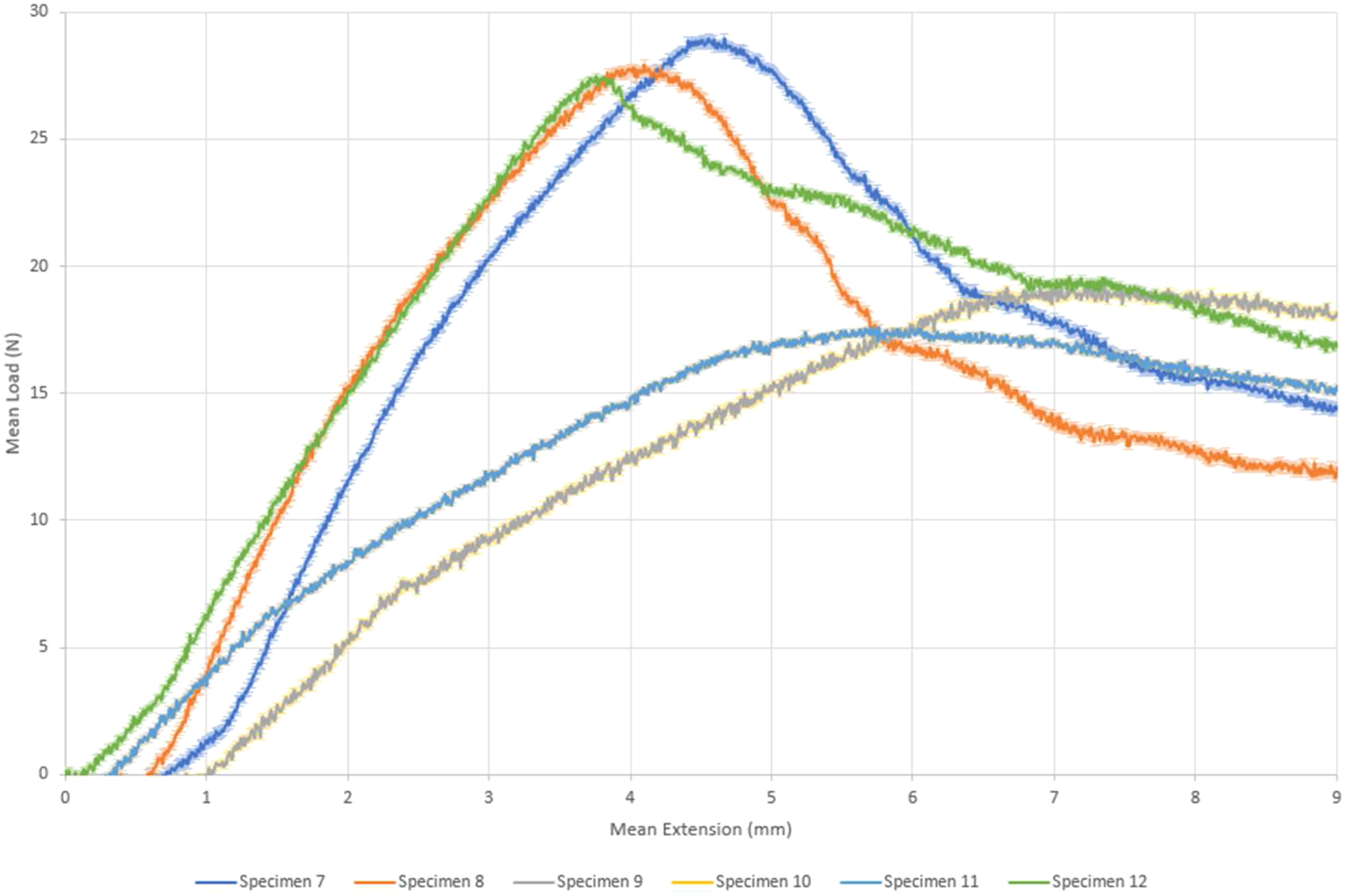
Further examination shows a somewhat more meaningful observation with regards to the mechanics of failure with polyimide coatings. Optical fibers were noted to have remained intact through testing. However, the specific drastic reduction in reported load showed a clean cleaving of interaction between the fiber and epoxy. References to Figures 11(a) and (b) show that the resulting cleavage was enough to create a significant spike in amplitude and counts above the threshold to the point that signals saturated the sampling window for amplitude. The timing of events was correlated in plots of time against experienced load comparisons, as shown in Figure 11(c). The size of these events and brevity of test duration shows that in tensile configurations, polyimide coatings appear to detach due to shear loading quickly within a 2,2 twill weave composite sample, and comparisons of Figures 12(a–c) indicate a similar trend, despite improvements to sample structural capacity. (a) Amplitude (dB) against time (sec) comparing specimen’s average 7, 9, and 11 (ply orientation of 45°) 2,2 weave under tensile loading. (b) Counts (n) against time (sec) comparing specimen’s average 7, 9, and 11 (ply orientation of 45°) 2,2 weave under tensile loading. (c) Mean load (N) against mean extension (mm) with error margin comparisons of tensile loading under constant extension of 10mm/min for different configurations within a 2,2 twill weave.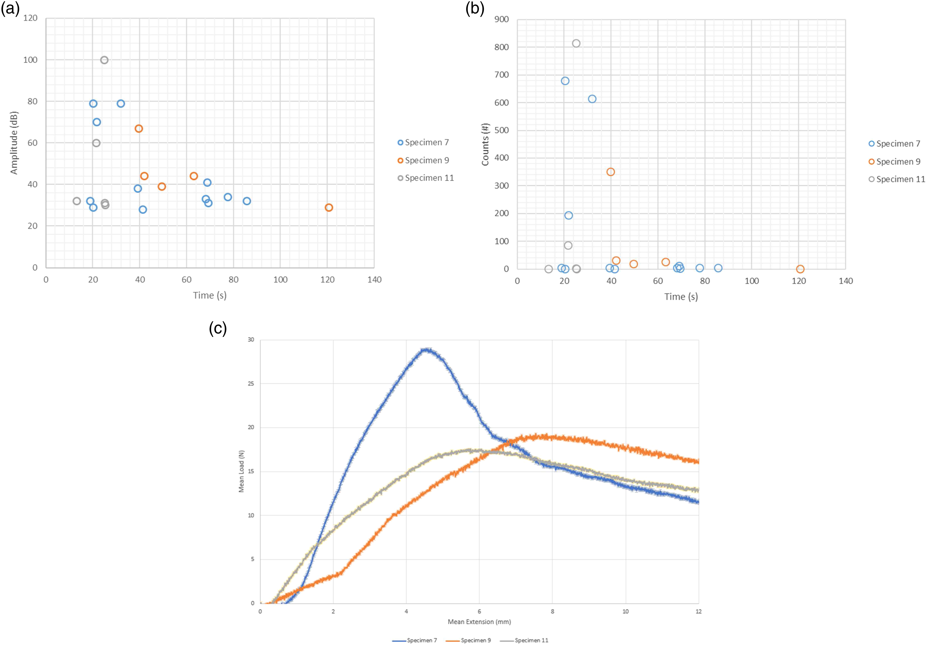
Tests reached higher tensile stress at a faster rate, potentially due to the reduction in plies within this configuration of the sample. The difference in weave thickness led to differences in epoxy distribution, which may have accentuated the discontinuity of an embedded fiber inclusion. However, similar patterns of clean shear cleavage of samples were observed within these samples.
It should be noted that assessment of the structural integrity of fibers was difficult to ascertain in their form of inclusion, within visible damage to functionality being hard to ascertain, and as such, assessments of shear interactions causing detachment of fibers from composite embedment was based on visual inspection of samples, however, with a large onset signal appearing from the 20 s mark within tests. Due to full saturation occurring within 28 s before the loss of events and a lack of noted loading at these points, the evidence suggests that the optical fibers were no longer supporting a tensile load and that fiber-reinforced polymer ends were moving freely, independent of the optical fiber.
However, comparisons of acrylate polymer-coated fibers showed a very different mode of behavior. Based on Figure 10, evidence suggests that structures continued to be a load-bearing structure in both coating thickness cases, even after when the large spikes were noticed in the Figure 11 and Figure 12 subsets and the perceived achievement of maximum tensile stress. Figure 10 appears to suggest that the tensile stress achieved by the smaller 169.6 μm diameter coated fiber was lower, with 241.4 μm diameter coated fiber achieving up to a 52% increase in tensile stress. However, the thinner acrylate coatings appeared to retain load-bearing capabilities to a higher level of efficiency than the steeper reductions seen in thicker coatings. Comparisons of Figure 11(c) with Figure 12(c) also appear to show a more pronounced effect within the 2,2 twill weave samples. The overall effect of coating diameter on the loading capabilities can be seen in Figure 13. (a) Amplitude (dB) against time (sec) comparing specimen’s average 8, 10, and 12 (ply orientation of 0°) biaxial weave under tensile loading. (b) Counts (n) against time (sec) comparing specimen’s average 8, 10, and 12 (ply orientation of 0°) biaxial weave under tensile loading. (c) Mean load (N) against mean extension (mm) comparisons of tensile loading under constant extension of 10mm/min for different configurations within a biaxial weave. (a) Mean average tensile stress (Mpa) against ply orientation (°) comparing groups of fiber orientations and weave types. (b) Tensile strain (mm/mm) against ply orientation (°) comparing groups of fiber orientations and weave types.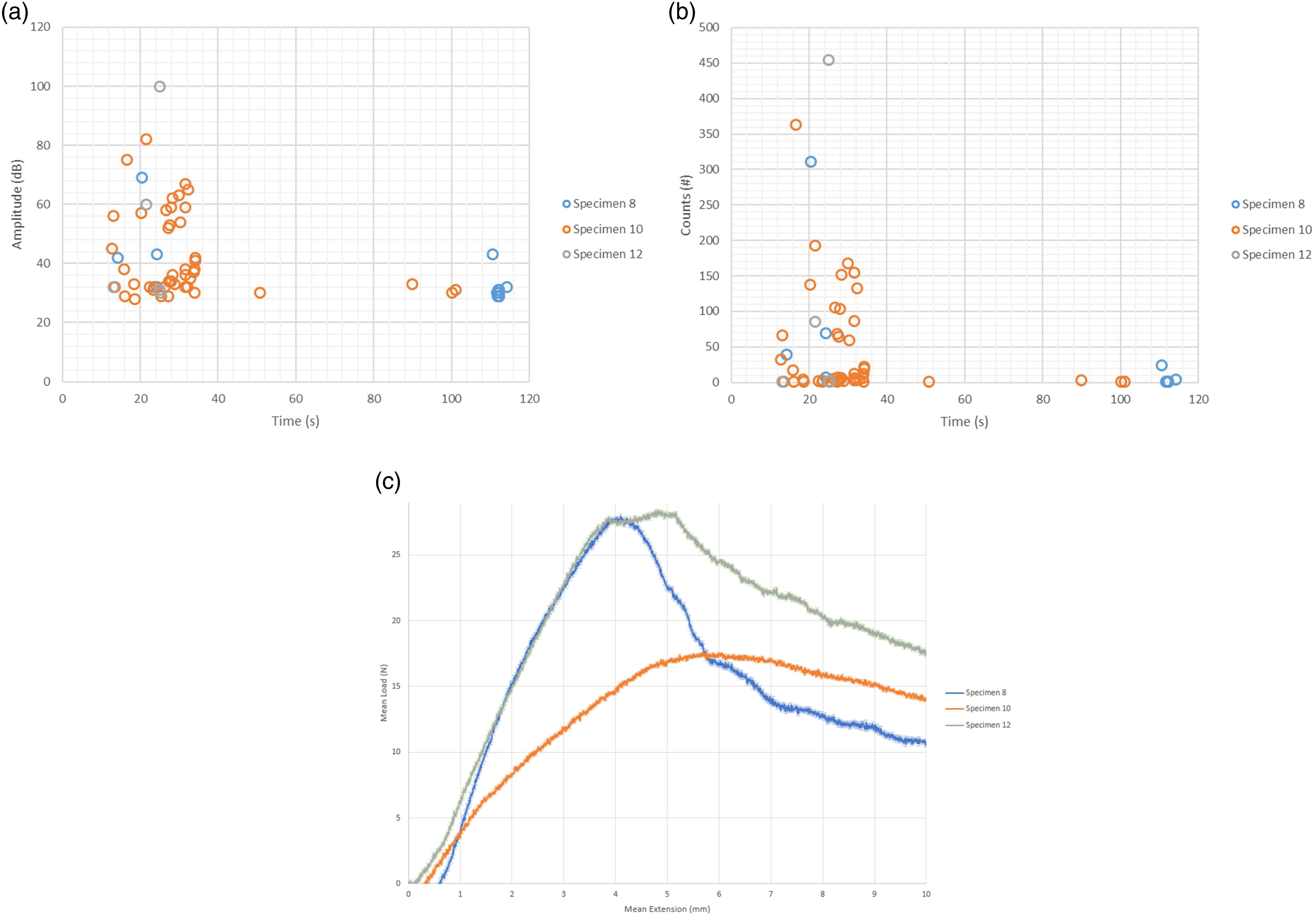
As previously alluded to, the inclusion of two extra plies in the 2,2 twill weave samples more likely attributed to a difference in ply spacing, and, as such, interactive adhesive interfaces could also have occurred with the carbon fiber directly, as opposed to the epoxy. This makes a significant change in interaction, as bonding between the acrylate monomer group and the graphitic carbon configurations facilitate different dipole orientations in response to the charge dispersion of carbon atoms and the carbon fiber’s functional coating treatments, in comparison to the valency of epoxide polymer units and their attached functional groups.
Furthermore, this new surface interaction comes with the potential for new adhesion mechanics through changes to wettability, which goes further than the macro-scale comparisons of this study.
When this is taken into account and the potential for higher dislocation and discontinuity with a larger fiber coating, this pronounced retention can be explained through the lesser level of material changes compared to a thicker coating.
The lower amplitude observed in Figures 11(a) and 12(a) compared to polyimide samples shows a different level of material absorption, with a reduction indicative of a more significant measure of adhesion between the fiber and the composite.
Both acrylate coatings showed an initial increase in the first instance of hit values, and the polyimide itself showed a large event depicting the high release of energy after the introduction of load that would suggest that the polyimide had a more significant energy release within the associated events, suggesting that the level of detachment seen within the polyimide samples was not observed within the acrylate specimens.
Stress onset within thicker coatings was more prominent, suggesting that the interactive effect was more significant, which would fall in line with the higher level of discontinuity. However, this is also a potential result of the greater surface area afforded by this coating having a stronger initial adhesive effect with the surrounding composite, which is supported by the larger tensile stress observed. The reduction in retention of material adhesion could be an effect of the much larger amount of bonds broken due to the maximum tensile stress achieved, with higher energy being required to cleave the bonds. Distortive changes to thickness in larger fiber coatings may have affected retention, with available dipoles no longer being capable of forming the Van der Waals interactions that were initially formed due to the presence of more prominent discontinuity voids with the resin.
The presence of hits past maximum tensile stress supports the concept of partial attachment, as counts of acoustic signals above the 30 dB threshold were still prominent in Figure 11(b) and Figure 12(b), particularly with the thinner coating diameter.
Within the scope of these tests, as previously mentioned, the interaction explored is more likely to be the interface of the epoxy resin with the optical fiber, with the carbon fiber playing a subdued role in structural integrity, but the stacking order, resulting reduction in ply numbers, and the changes to both fiber volume ratio and ply spacing cause an effect, as biaxial samples performed noticeably worse in terms of potential maximum tensile stress and surface interactions.
As previously alluded to, the lack of interaction with the carbon fiber may have led to a more pronounced reduction in load-bearing capability retention seen by the thicker diameter acrylate samples, as seen in Figure 12(c). More prominently, the larger void created as a result of the new spacing in a resin-rich area may have been more difficult to retain bonds within due to the loss in the wetted contact surface. This would explain why tensile stress values were failure similar despite these changes, as the tensile stress assessments solely tested the epoxy interface with optical fiber coatings before adhesion failure.
Conclusions
The mechanical characteristics of the composite material with embedded optical fibers were evaluated within this work.
Following novel approaches in testing of embedded optical fibers within two ply configurations with consideration of coating composition and thickness in two modes of loading, several findings could be determined from this study from different viewpoints.
Whilst most literature points to optimal placing of embedded sensors with respect to ply orientations to be unidirectional, in a practical scenario, this is not always possible due to the preferential tailoring of stacking orders in fiber-reinforced polymers for loading capability. In this sense, this study has shown the importance of relative optical fiber orientation and its effect in combination with different woven fiber arrangements, differing ply orientations, and different stacking orders.
Data suggest that coatings perform differently based on different forms of loading within different weaves, with evidence suggesting that acrylate coatings offer better adhesion and loading capability in tensile situations and showing less compromise in both stress and strain configurations for transverse load applications, in comparison to the significant trade-offs seen within polyimide coatings. There was a 44% increase in the Young’s modulus of 2′2 twill weave fiber arrangements when a polyimide coating was used in comparison to a larger diameter acrylate-coated fiber, but there was a reduction of 3.5% when the thinner acrylate one was used in comparison to the even thinner polyimide one which had a lower surface wetted surface area as a whole.
With the help of AE data comparatives, in both tensile and flexural loading testing, monitoring of emissions confirmed the significant role that coating thickness appears to play, with different effects being present when under tensile and transverse loads.
Optical fiber coating thickness appeared to reduce the effects of discontinuity in transverse load applications and has a significant role in retention of adhesion with the formulated resins under tensile load as shown by the reduction in polyimide-coated samples. However, the explorative scope of this study suggests that further intensive studies on the effects of thickness are needed to determine the effects for practical solutions.
This plays a significant role in the design of smarter materials applications, where trade-offs in stacking order, weave patterns, and ply orientations are required, along with sensory components. Optical microscope analysis solidified this, with more pronounced signs of delamination and changes to fiber occurring in 45° orientation 2,2 twill weave patterns in line with its lower resistance to a transverse load under 3-point bending.
Furthermore, the explorations into off-axis sensor embedment inside material components that have been tailored to fit loading applications is a more complex affair than indicated within the current state of the art, with evidence suggesting that the selection of coating material and of coating thickness, along with sensor orientation is a significant material consideration that needs to be further explored, based on the mechanical analysis.
Furthermore, in a practical setting, this needs to be considered carefully when embedding sensors, as evidence suggests that different configurations of fiber coating composition, relative angular placement, and fiber coating thickness can have a significant effect in functionality and load-bearing capability depending on the application of the monitored parts in question, with the performance of acrylate coatings and their interaction with an epoxy matrix under tensile loading in particular, raising questions about the current state of research in this field suggesting polyimide coatings as the preferred coating material.
This was further enhanced through the non-contact monitoring of samples showing different behavioral effects, with amplitude and counts monitoring showing the reduced energy emissions effect in transverse loading, and the evidence in the tensile test based on events above threshold showing signs of adhesion retention in comparison to the clean cleavage observed in polyimide coated samples.
It should be noted that this study pertained to the structural and mechanical behavior of embedded sensors, and the functional capability of the optical fibers was not explored. However, further work is needed to determine changes to the functional effect of sensors. Whilst results such as the tensile tests show the severe limitations in using polyimide coatings, as detachment effectively nullifies the ability to sense the strain of the surrounding material when integrated with a fiber Bragg grating, there is a need to further investigate the changes on light transmission through the fiber under loading with these variations to determine the effects on functional capability.
Footnotes
Acknowledgments
The authors would like to acknowledge the support of this research provided by G. Miles, of the Warwick Manufacturing Group, R. Ramos, of Fibercore Ltd. and A. Hunt of Atout Process Ltd.
Declaration of Conflicting Interests
The author(s) declared no potential conflicts of interest with respect to the research, authorship, and/or publication of this article.
Funding
The author(s) disclosed receipt of the following financial support for the research, authorship, and/or publication of this article: This research was funded by G. Miles, of the Warwick Manufacturing Group, R. Ramos, of Fibercore Ltd. and A. Hunt of Atout Process Ltd.