
Abstract
Perforated plates are widely used in thin-walled engineering structures, for example, for lightweight designs of structures and access for installation. For the purpose of analysis, such perforated plates with two opposite free edges might be considered as a series of successive Timoshenko beams. A new semi-analytical model was developed in this study using the Timoshenko shear beam theory for the critical buckling load of perforated plates, with the characteristic equations derived. Results of the proposed modelling were compared with those obtained by FEM and show good agreement. The influence of the dividing number of the successive beams on the accuracy of the critical buckling load was studied with respect to various boundary conditions. And the effect of geometrical parameters, such as the aspect ratio, the thickness-to-width ratio and the cutout-to-width ratio were also investigated. The study shows that the proposed semi-analytical model can be used for buckling analysis of a perforated plate with opposite free edges with the capacity to consider the shear effect in thick plates.
Introduction
In box girders and some load-bearing spars, cutouts are made for special purposes, for example, material saving and weight reduction, access for installation and inspections.1–4 Generally, plates with cutouts have a relatively lower structural strength in comparison with those without, and the buckling behaviour is one of the most critical considerations in safety and reliability of these structures. The buckling analysis of a plate with cutouts is more complicated than that of an intact plate. 5 Many relevant studies have involved numerical, experimental and analytical techniques, and their combinations. Recent works in numerical simulation include Tao, 6 who employed a FEM approach for elastic stability of perforated plates under uniaxial compression, and the parameters with significant effects on the performance of the plates were proposed. Paslara 7 investigated infill plate boundary condition effects by FEM on the overall performance of steel plates with circular openings. And Loughlan 8 adopted finite element modelling strategies and solutions procedures to enable the determination of post-buckling failure responses of steel plates with cutouts. More studies were seen on the elastic buckling behaviour of rectangular plates with cutouts for partial edge loading, 9 the elastoplastic buckling behaviour of simply supported rectangular plates with elliptic cutouts 10 and the post-buckling behaviour of thin plates with central circular cutouts subjected to biaxial load 11 using FEM.
Experimental studies were also frequently seen together with simulations.12–14 Shin 15 tested five perforated web specimens subjected to simulated loadings, and nonlinear buckling analyses were performed by FEM to compare with the observed inelastic mechanisms. A series of experimental tests 16 were carried out for the ultimate buckling load of perforated steel plates, and FEM was used to investigate the coupling relations between the geometrical parameters and the buckling behaviour.
Though there have also been numerous reports on analytical approaches for intact plates, for example, Refs. 17–22, few are seen in open literature on plates with cutout. Ovesy 23 adopted a Reddy-type, third-order shear deformation theory of plates for two versions of the finite strip method to predict the behaviour of the moderately thick rectangular plates containing central cutouts, though the approaches given are not applicable for all boundary conditions. Abolghasemi 24 applied the Ritz method and expanded the stress function in polar coordinates for circular cutouts to calculate the buckling load. The buckling behaviour of the panel with the rectangular cutout was predicted by applying Lekhnitskii theory and the complex variable method 25 to express the strain distribution around a rectangular opening of an infinite anisotropic plate. These analytical solutions were obtained by expressing the stress and strain distributions along the cutout edges, resulting in rather complicated analytical solutions. Furthermore, these analytical solutions are generally applicable only to special cases, such as circular or rectangular cutouts, 26 and in simple boundary conditions. More recently, a number of studies were seen making use of the energy methods.27,28 And the critical buckling load of new materials such as cellular or corrugated materials were considered, including the adoption of equivalent shapes of opening.29–32 Some simplified approaches on the structural profiles were also made, such as equivalent cross-sections for engineering applications.33–35
For perforated plates with opposite free edges, the local stress and strain distributions along the cutout edges are not significant to affect the buckling behaviour of the plate. The buckling behaviour is more of a global one, thus less sensitive to local elements. To provide a relatively straightforward approach for buckling analysis of plates with cutouts, this work proposes a new semi-analytical model based on the Timoshenko beam theory to solve the critical buckling load, which can be reasonably easily applied to plates with symmetric cutout shapes. The new approach differs from existing published work in its advantage of simplicity in the numerical solution of the analysis model and the versatility in handling a variety of symmetric cutouts.
Problem description
The geometry of the cutout considered in this study can be of the shape of a circle, an ellipse, a rhombus or an even-sided polygon, or others, which can be symmetrical to the central axis of the plate. As a circular cutout is most widely used in practice, it is chosen here to demonstrate the analysis. The geometry is described in Figure 1 with the plate of length a and width b. The circular cutout in the middle of the plate has a diameter d. The plate edges AB and CD can be simply supported, fully clamped or have no constraint, respectively, as the boundary condition. And edges AD and BC are assumed free with no constraint. A uniformly distributed compressive load, F
P
, is applied on AB and CD. Perforated plates with opposite free edges (AD and BC).
Figure 2 shows that the perforated plate is decomposed into three connected sections in the axial direction: the left and right full-width sections, ABB’A’ and D’C’CD, respectively; they are intact beam sections, with A’B’ and C’D’ being tangential to the cutout circle, which is centred at (a/2, b/2). Both sections can be considered as two separated Timoshenko
36
beams. The middle section, A’B’C’D’, has a circular cutout, for which the remaining part of the section can be treated as a series of successive Timoshenko sub-beams, with each sub-beam of a rectangular shape in various heights fitting the circumference of the circular cutout. Note that due to the symmetry to the beam axis, there is an identical upper and lower group of sub-beams, correspondingly. Successive Timoshenko sub-beams for perforated plates.
Setting the point O at the middle of AB as the coordinate origin with the x axis being the central line of the beam, the y coordinate of the circular cutout outline can be expressed by equation (1)
The total division number of sub-beams, n, is assumed to be even. And if the sub-divisions are taken at equal length for simplicity, for the ith sub-beam, its end coordinate, x
i
, and width (or height), b
i
, can be given by equations (2) and (3)
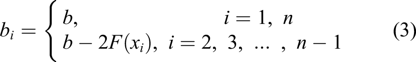
Note that both the upper and lower sub-beam groups need to be considered. And as an approximation for simplicity, they are ‘lumped’ together in height as b i accordingly.
Analytical buckling model of perforated plate structures with opposite free edges
Buckling model expressed by the Timoshenko beam theory
The infinitesimal segment in the ith Timoshenko sub-beam is shown in Figure 3 with the transverse displacement dw
i
. Its corresponding bending and transverse shear stiffness are D
i
= E
i
I
i
and B
i
= G
i
A0i = G
i
A
i
/ψ, with E
i
, I
i
, G
i
, A
i
and ψ being the Young’s modulus, the moment of inertia, the transverse shear modulus, the area of the cross-section and the shear correction coefficient, respectively. ψ = 1.2 for a rectangular cross-section. The rotation angles of cross-section in Euler–Bernoulli and Timoshenko beam theory are θ
i
and φ
i
, respectively, and the angle γ
i
is caused by considering the shear deformation in the Timoshenko beam. Infinitesimal segment in the ith Timoshenko sub-beam.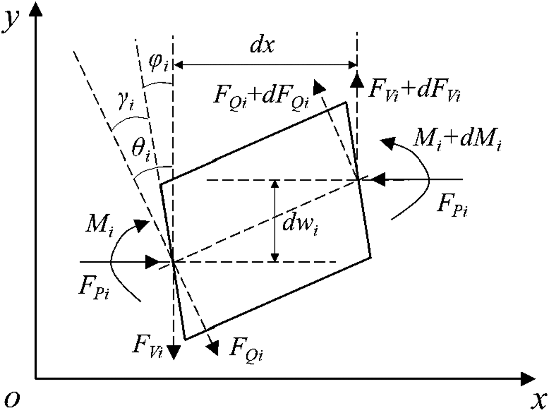
Considering the shear deformation shown in Figure 3, the rotation angles of the cross-section can be given as
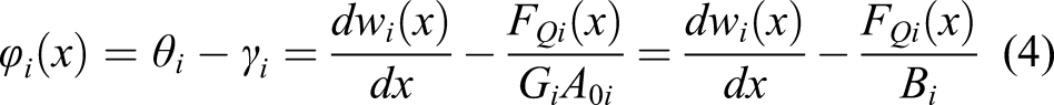

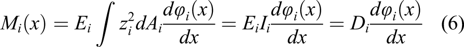
equation (4) can be written as
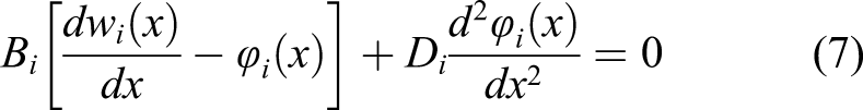
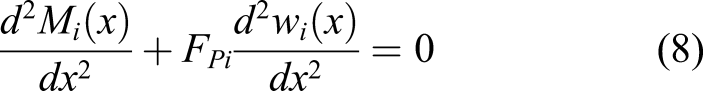
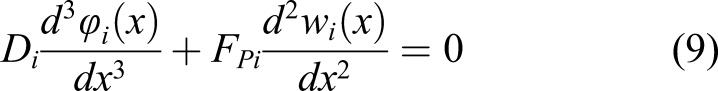
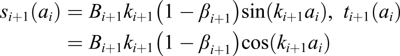
The governing buckling equations of the ith (i = 1, 2, …, n) Timoshenko sub-beam can be expressed by equations (7) and (9). And the general solution can be obtained by the transverse displacement and the angle of rotation


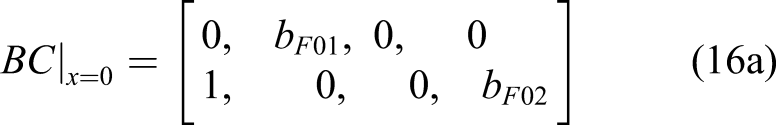
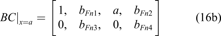
Boundary conditions
Various boundary conditions for edge AB and CD can be expressed. Three of the commonly seen types are given as follows:
(1) Simply supported (S): At x = 0 and x = a

(2) Fully clamped (C): At x = 0 and x = a

(3) Free of constraints (F): At x = 0 and x = a


Continuity conditions
The physical requirement of continuity between neighbouring sub-beams of a smooth plate structure requires the following conditions to be satisfied for the transverse displacement, the angle of rotation, the bending moment and the shear force: (1) Transverse displacements: At x
i
= a
i
, i = 1, 2, …, n−1


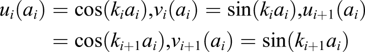

(2) Angles of rotation: At x
i
= a
i
, i = 1, 2, …, n−1


(3) Bending moments: At x
i
=a
i
, i=1, 2, …, n−1


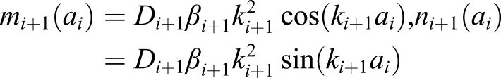
(4) Shear forces: At x = a
i
, i = 1, 2, …, n−1


The buckling solution matrix
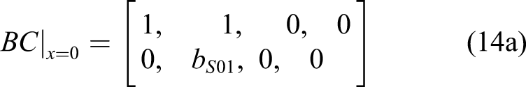
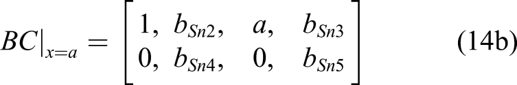
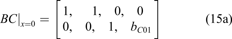
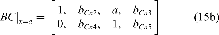
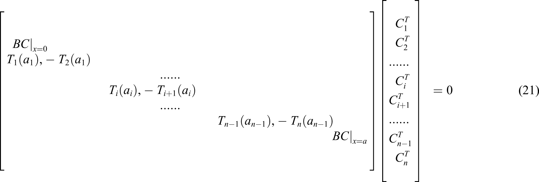
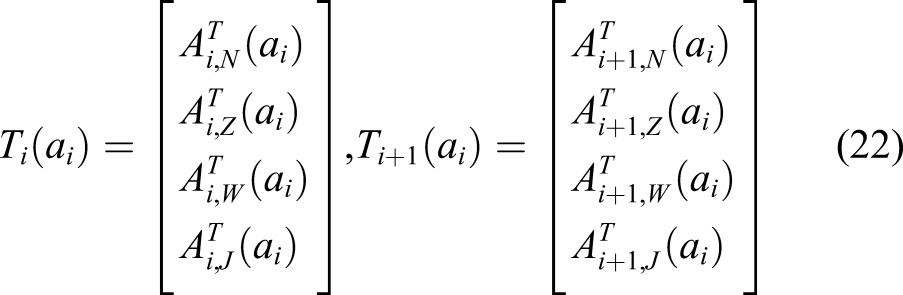
For simplicity, simply supported edges were chosen as the example for discussion. One set of equations consists of four boundary conditions from equations (14) and 4(n−1) continuity conditions from equations (17–20), leading to a total of 4n equations for 4n unknown coefficients. These equations are linear and can be written into a matrix format
The critical buckling force,
Finite element model for verification
Detailed results corresponding to buckling of plates with cutouts are very limited from open literature. In order to verify the outcome of the proposed semi-analytical model, a FE model using ANSYS 37 was developed to compare the results, including a parametric study. In the FE model, SHELL181, a four-node element with six degrees of freedom at each node, was chosen. It is suitable for analysis of thin to moderate thick shell structures with large rotations and strains. In this work, the quadrilateral gridding was adopted to mesh the perforated plate.
Edges AB and CD, as shown in Figure 1, were set to either simply supported or clamped boundary condition and edges AD and BC to free of constraints. A uniformly distributed compressive load was applied on AB and CD. Convergence tests were carried out to ensure good results. Figure 4 shows a typical mesh pattern of a quarter of the model. Finite element meshes of perforated plates with opposite free edges.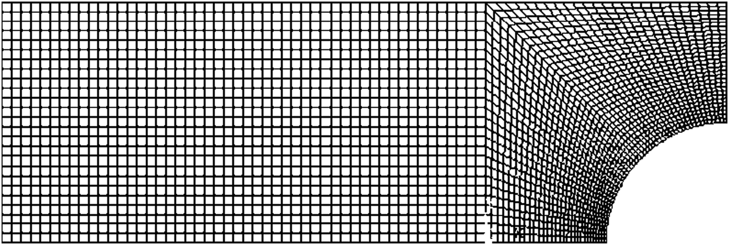
Results and discussions
Validation with the FE Model
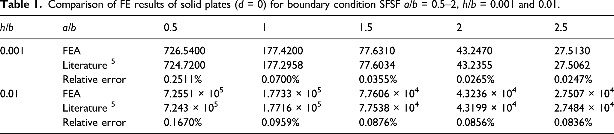
Comparison of FE results of solid plates (d = 0) for boundary condition SFSF a/b = 0.5–2, h/b = 0.001 and 0.01.
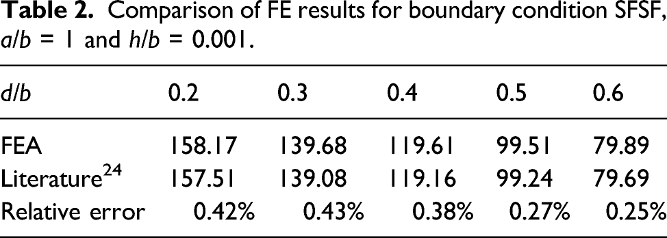
Comparison of FE results for boundary condition SFSF, a/b = 1 and h/b = 0.001.
Division number of the sub-beams
As the division number of the sub-beams in the proposed model, N (= n−2) can be selected differently, the influence of the choice was investigated. Due to the geometric symmetry, the division was always evenly numbered and tested from 4 to 18, respectively, with the results compared to the FEM results.
Considering the geometrical parameters in practical engineering applications, cases of three different plate thickness were chosen for the relative errors in the critical buckling load with respect to the division number, as shown in Figure 5. For the thinner plate (Figure 5(a), h/b = 0.001 and Figure 5(b), h/b = 0.01), for any division number from 4 to 18, the relative errors are always within 5%. For the thicker plate (Figure 5(c), h/b = 0.1), the relative errors also will not exceed 6% for any division number from 4 to 18. Relative errors of the critical buckling load in terms of the sub-beam dividing number.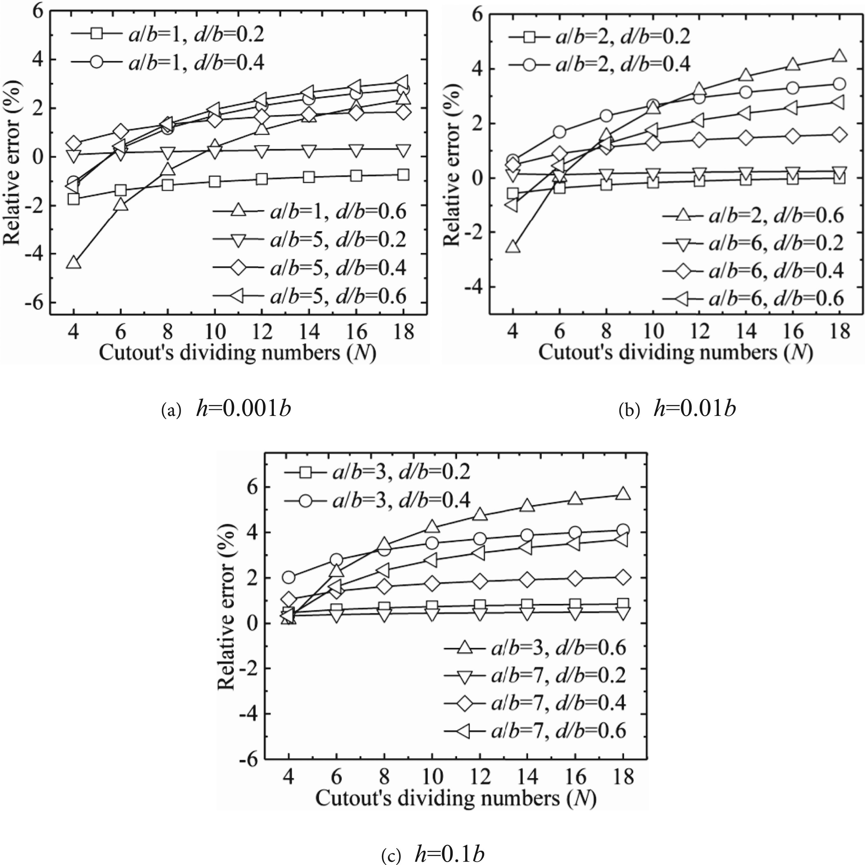
As shown in Figure 5, the relative errors to the corresponding FEA results are broadly small, for instance, within 5% for a division number in the range from 4 to 12 or 4 to 18 for 6% relative error. In other words, results are not sensitive to the selection of the division number, and a larger one does not necessarily help to improve accuracy. The recommended number is between 4 and 18 for calculation efficiency.
Applicability of various boundary conditions
Four different boundary conditions were considered, starting from the left side in the clockwise direction, SFSF, CFCF, SFCF and CFFF. The critical buckling loads corresponding to the four boundary conditions are illustrated in Figure 6. Five values of the aspect ratio (a/b = 1–9) were analysed for d/b = 0.4 and h/b = 0.1. Results from the proposed model are virtually identical, especially as the aspect ratio a/b is from 6 to 9, to those of the corresponding FE model, and the aspect ratio will be chosen from 1 to 5 in the following parametric analysis. The critical buckling load can be seen reducing with respect to the aspect ratio. Critical buckling loads versus the aspect ratio under various boundary conditions, d/b = 0.4 and h/b= 0.1.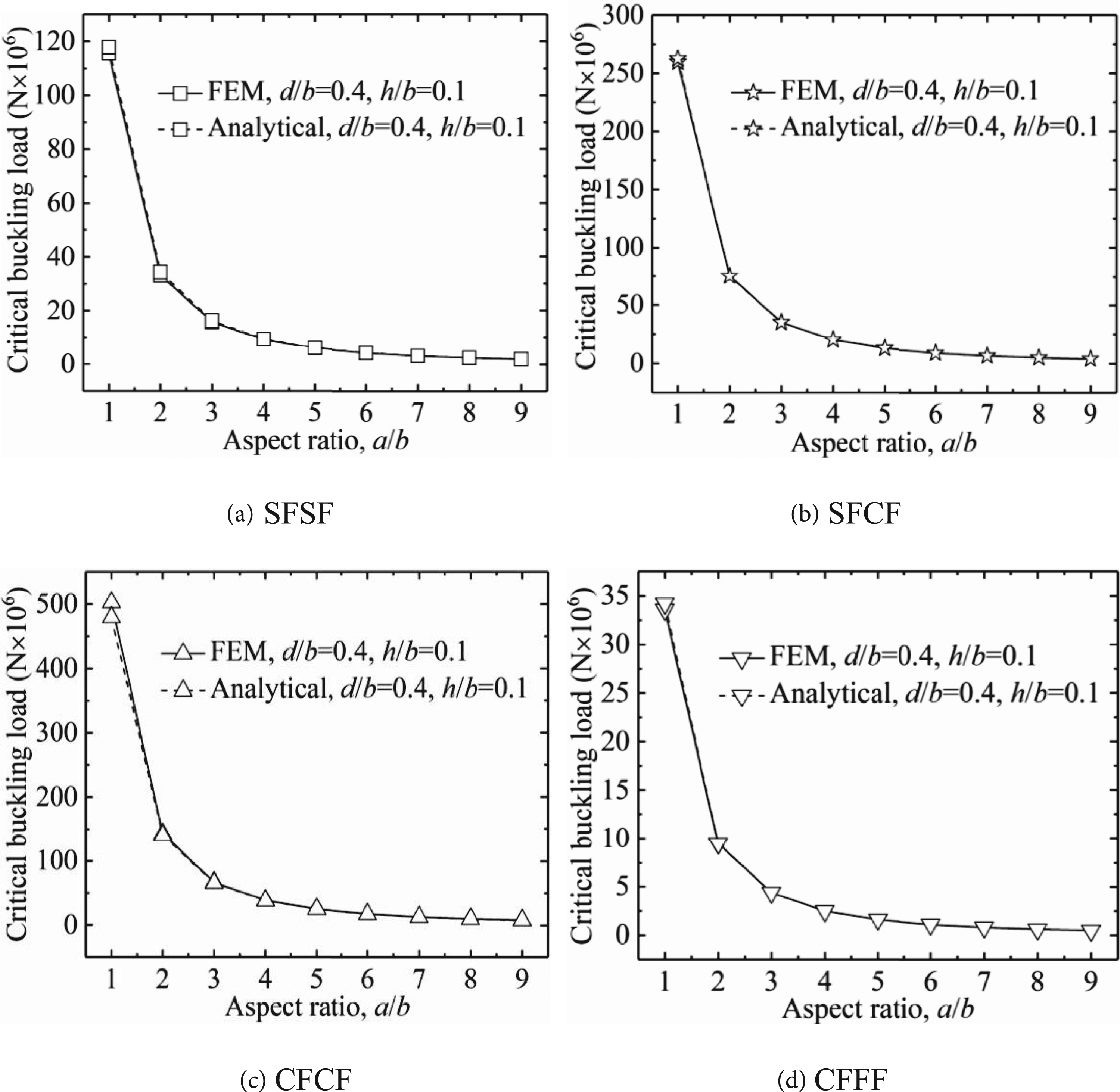
Effect of geometrical parameters on the critical buckling load
Three non-dimensional geometrical parameter sets, that is, the length-to-width (aspect) ratio a/b, the thickness-to-width ratio h/b and the cutout-to-width ratio d/b, were studied, respectively, for their influence on the critical buckling load with the boundary condition case SFSF.
The aspect ratio a/b
Five values of the aspect ratio (a/b = 1–5) were considered with two cutout-to-width ratios (d/b=0.2 and 0.6) and two thickness-to-width ratios (h/b = 0.001 and 0.1), respectively, as shown in Figure 7. It illustrates that the critical buckling load reduces with respect to the aspect ratio. And the orders of the magnitude of the critical buckling load are different due to the difference in the plate thickness, but the changing trend of the critical buckling loads is similar. Effect of the aspect ratio on the critical buckling load, d/b = 0.2 and 0.6.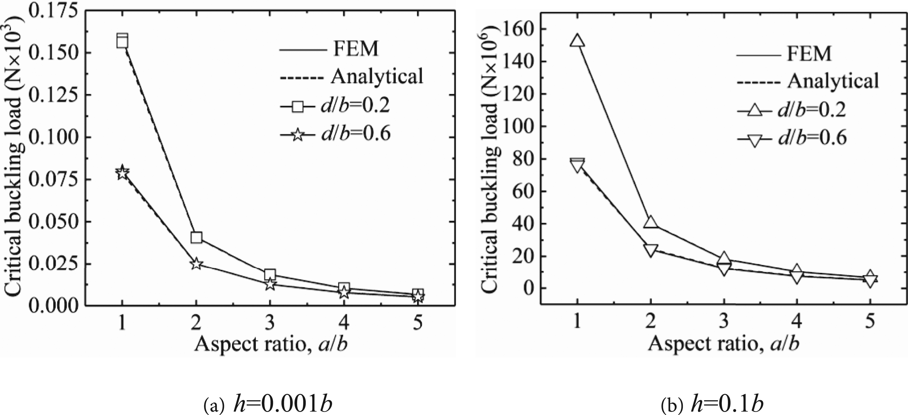
A bigger cutout understandably yields a lower critical buckling load due to the long and thin successive sub-beams above and below the cutout. And the critical buckling loads of the two different-sized cutouts show a converging trend in terms of the aspect ratio. This is due to the increasing slenderness of the plate in terms of the aspect ratio in which buckling becomes more of a global effect and less sensitive to local features such as the cutout.
The thickness-to-width ratio h/b
The influence of the thickness-to-width ratio was studied in five cases (h/b = 0.001–0.1) with two cutout-to-width ratios (d/b = 0.2 and 0.6) and two aspect ratios (a/b = 1 and 5). The critical buckling loads are given in Figure 8; for the thickness-to-width ratio h/b and the critical buckling load, the load can be seen to increase with respect to the thickness-to-width ratio due to the higher moment of inertia of the cross-section of thicker plates. A bigger cutout yields a lower buckling load. And a bigger aspect ratio leads to a lower critical buckling load, as the slenderness increases. Effect of the thickness-to-width ratios on the critical buckling load.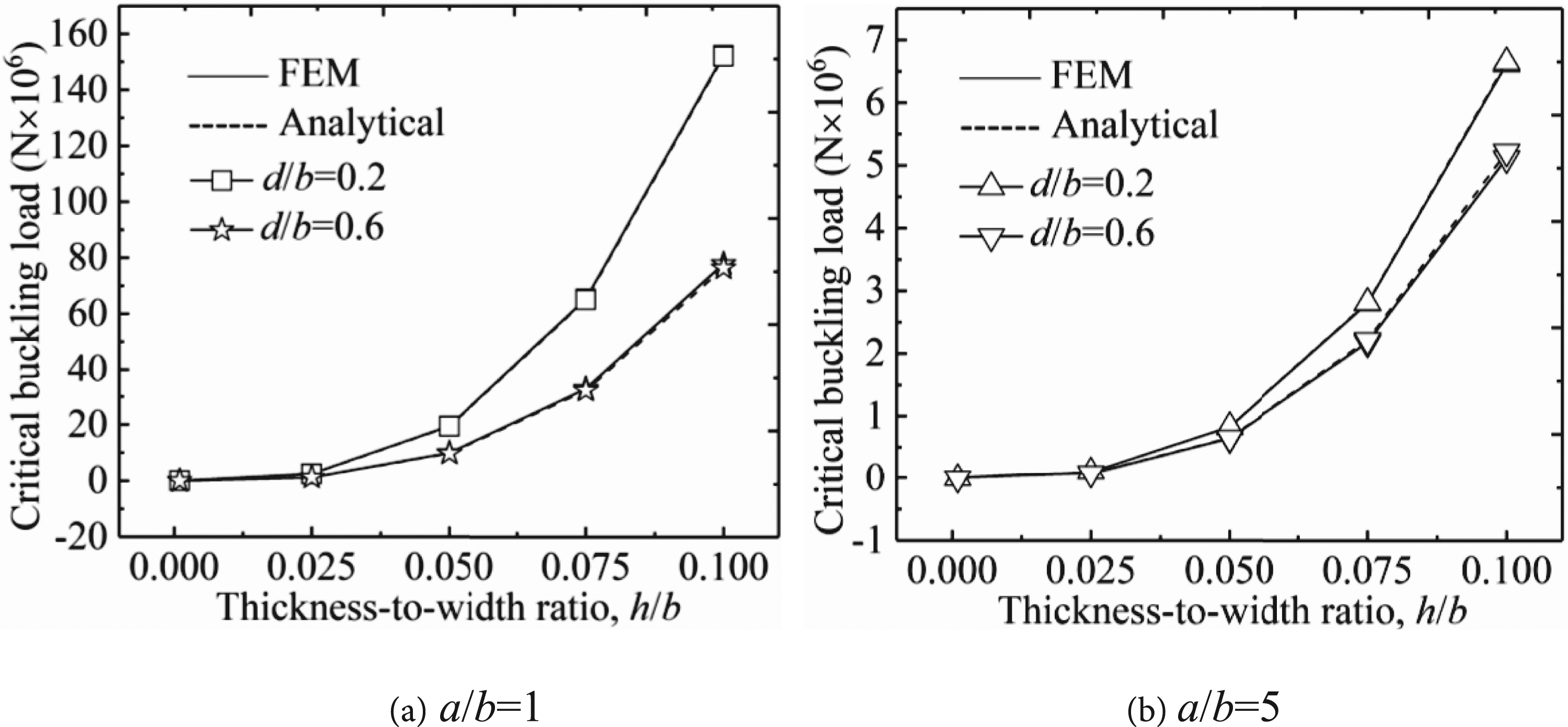
The cutout-to-width ratio d/b
The effect of the cutout-to-width ratio (d/b = 0–0.6) on the critical buckling load is given in Figure 9, where two thickness-to-width ratios (h/b = 0.001 and 0.1) and two aspect ratios (a/b = 1 and 5) were considered, respectively. The critical buckling load of solid plates with no hole (d/b = 0) are also included for comparison. It can be seen that the critical buckling load decreases with the cutout diameter over the diameter range considered. As expected, a bigger cutout weakens the plate more, leading to a lower buckling strength. The aspect ratio also has a significant effect on the critical buckling load with scale changes in the magnitude of the buckling load for both plate thicknesses.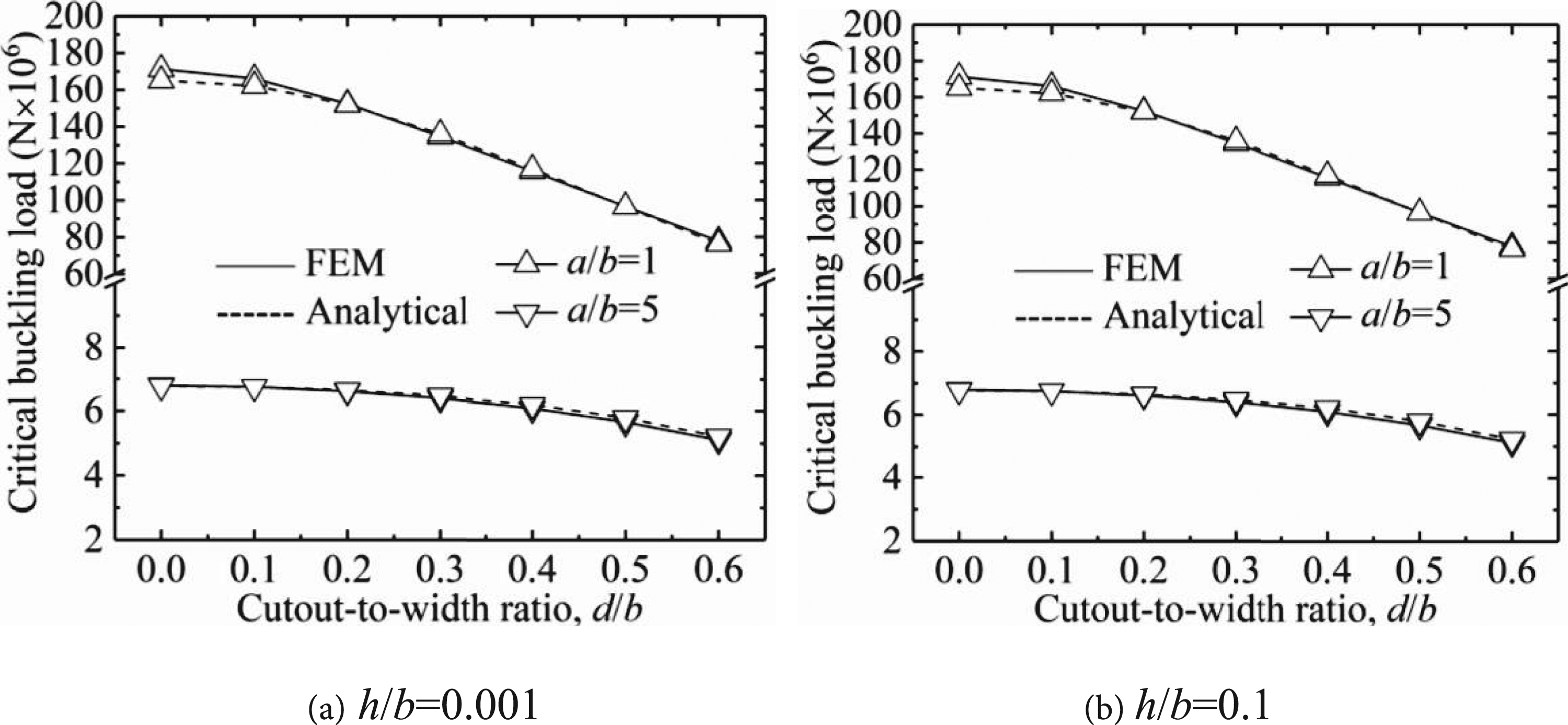
Applicability of different cutouts
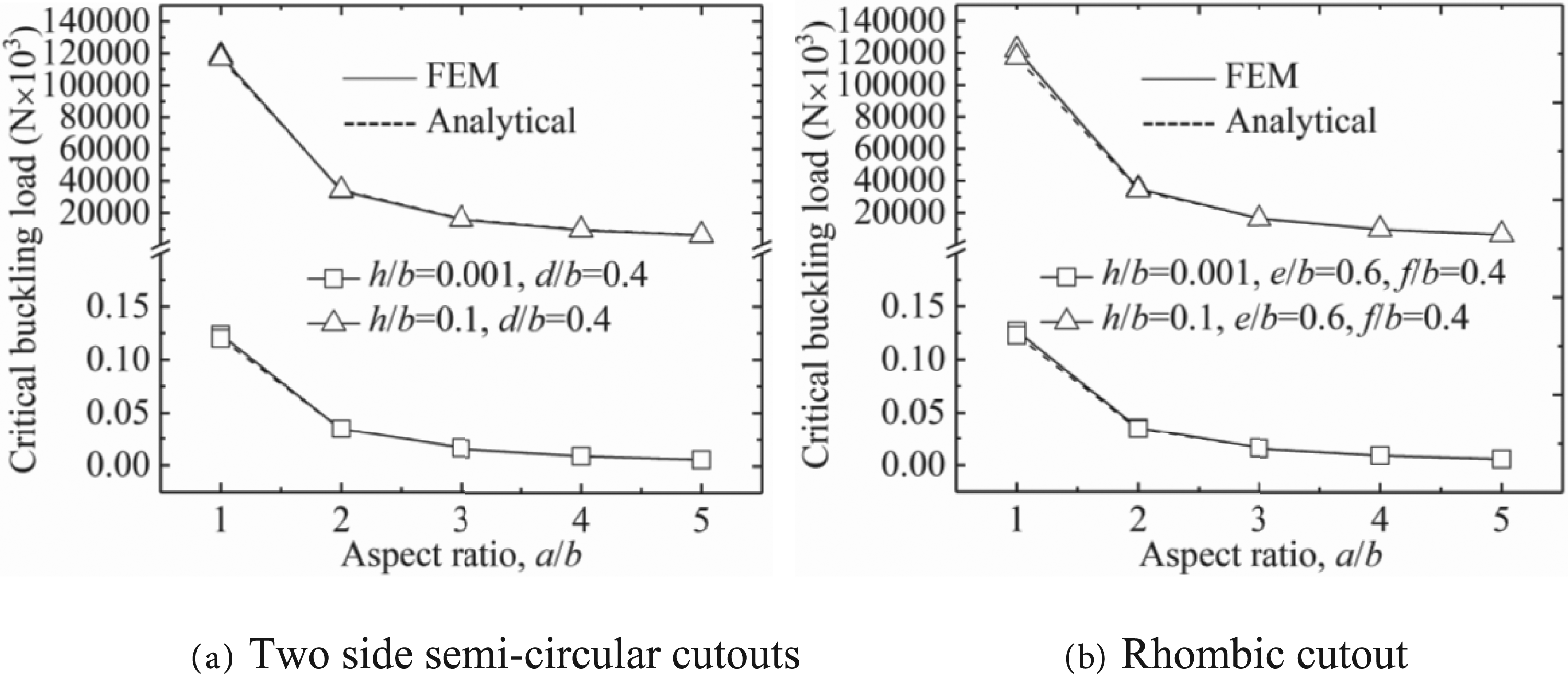
1-Side Cutouts
The proposed new model can also be applied to analyse plates with side semi-circle cutouts and rhombic cutouts. Figure 10(a) shows two semi-circular cutouts of the same diameter on the opposite sides of the beam parallel to the beam axis Plate with opposite free edges containing two different cutouts. Effect of the aspect ratios on the critical buckling load for two different cutouts, d/b = 0.4.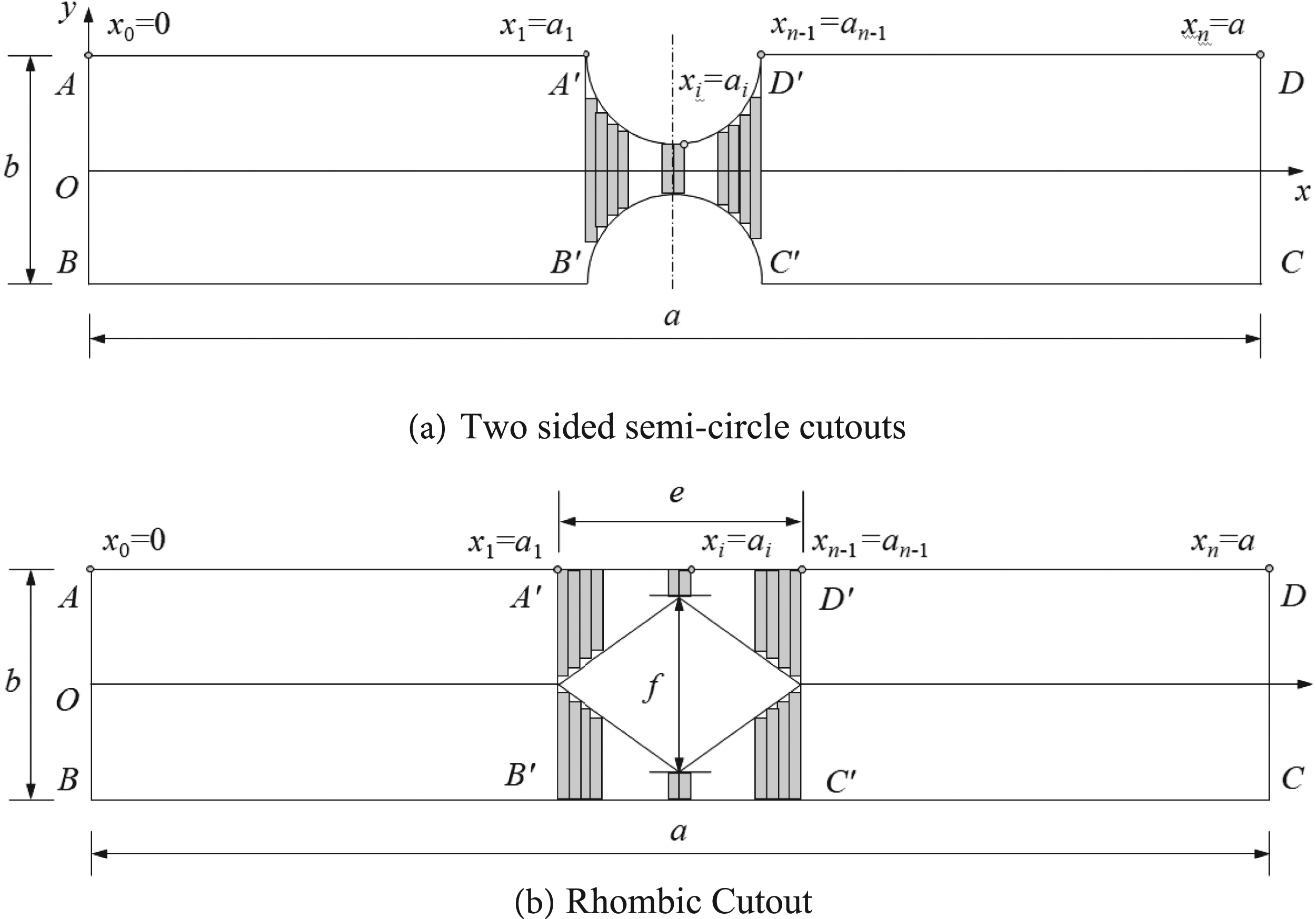
Conclusions
A new semi-analytical modelling technique based on the Timoshenko shear beam theory was introduced to calculate the critical buckling load of perforated plates with opposite free edges. The rectangular plate was treated as a series of successive sub-beams using the Timoshenko beam theory. Plates with a central circular cutout were discussed as case studies, and the results were compared with those obtained from FEM, showing good agreement. The selections of the division number of the sub-beams can be flexible within a practical range from 4 to 18 for computation, over which a good accuracy can be maintained (within an error of 6% to the FEA results) with little sensitivity shown in the results to the division number selection. Overall, the proposed model is relatively simple and straightforward to use for calculation of the buckling load of perforated plates with opposite free edges with cutouts.
Calculations show that with the boundary condition SFSF, the critical buckling load increases by reducing the aspect ratio a/b and increasing the thickness-to-width ratio h/b, respectively, and by the cutout-to-width ratio d/b in an approximately linear relationship or a weak quadratic one in normal linear scales.
One of the clear advantages of the proposed model is its capacity to handle different geometries of cutouts. Cutouts of elliptical, rhombic, evenly sided polygonal and other shapes of profile with a symmetric character to the axis of the perforated plates can be analysed accordingly, including both central and sided cutouts. In fact, one may combine different geometric shapes together for the cutouts.
However, it needs to be pointed out that specifically for rectangular-shaped cutouts, if the cutout-to-width ratio is big, the proposed model will not give accurate results. As the difference in the heights of the neighbouring sub-beams along the vertical cut line could become too big, there would be a significant jump in the distributed load between the neighbouring sub-beams, yielding big errors. This particular case remains to be studied further.
Footnotes
Acknowledgements
The authors also acknowledge the anonymous reviewers for the comments to improve the manuscript.
Declaration of conflicting interests
The author(s) declared no potential conflicts of interest with respect to the research, authorship, and/or publication of this article.
Funding
The author(s) disclosed receipt of the following financial support for the research, authorship, and/or publication of this article: The authors are grateful of the financial support to this work by the International Exchanges Programme Scheme of the Royal Society and the National Natural Science Foundation of China (51811530311) and the China Scholarship Council (201808515166).