
Abstract
Current aero-engine sealing materials are reaching their operating limit, as manufacturers seek more efficient engines with longer service lives. Even when utilised in optimum conditions, current materials have inconsistencies in performance due to variabilities in their microstructure, which lead to undesirable responses and events. As such, a new generation of sealing materials is required. Metallic foams are one such material, given the opportunities that exist to both engineer material properties, and achieve relatively consistent microstructures when compared to the current class of thermally sprayed abradable materials. In this study, the abradability of a nickel (70%)–chromium (30%) (NiCr) alloy foam is investigated, with the role of cell size and filler material considered. Tests are performed on a representative high-speed test rig, where a flat blade is used to simulate an aero-engine incursion event. A series of in situ measurement techniques, such as force, temperature and stroboscopic wear measurements are used to characterise the incursion, with DIC (Digital Image Correlation) techniques also employed to investigate breakdown of the foam. Unfilled foams were shown to lead to high blade wear, with the inclusion of filler materials leading to load transfer and collapse of the foam away from the incursion site, along with improved fracture. Both load transfer and ligament collapse mechanisms were found to promote more favourable rub mechanics at all incursion rates tested.
Introduction
Aero-engine sealing usually consists of an abradable layer positioned between the rotary and stationary components present within compressor shaft seals. 1 Sealing coatings are sacrificial, giving their structural integrity for the benefit of the component and are subject to abrasion, erosion oxidation, incursive rubs and extreme thermal, mechanical and impact loading conditions. 2 This is done to minimise the clearance with an ultimate aim to protect the blade and casing from significant damage and wear to achieve better aerodynamic efficiency.3,4 In the compressor, different abradable material blade combinations are used depending on the thermal load at a given stage of the engine. In each case, material removal mechanisms and material characteristics have been investigated. The aim of this metallic foams testing has been to improve performance and where opportunity exists to control incursion rates during running and handling, to ensure well cut surfaces.
In return through the reduction of nominal clearances between rotating blade disks and the surrounding casing, this greatly lowers operating costs and fuel consumptions whilst also improving engine performance.5,6 For example, Nyssen provides a detailed model to predict and validate contact forces often seen between blade and disc providing an approach to optimise clearances. Similarly, Delebarre investigated AlSi seal interaction with nickel alloy producing a quantitative approach to the interaction forces through study of micrographs to best quantify the wear behaviour and mechanisms. 7 Finally, in exploring material performance, Nitschke has investigated with a high-speed test rig the interaction of real engine rotor blades with a casing segment, outlining the capability of such instrumentation to best quantify the performance of like materials. 8
Engine designers are now moving towards hotter engines, calling for harder abradable material compositions and harsher running conditions.9–11 Aside from thermal limitations of current materials for future engine platforms, today’s abradables also face issues due to the manufacturing process of these coatings, where large variability exists within the microstructure. This leads to variations in response for even nominally similar materials. Furthermore, under optimum operating conditions due to the localities of material properties, problems such as damaging of seals and blades and debris formation can still persist.12,13 These are all challenges for future abradable materials for clearance control, and this work will investigate a new construct of NiCr materials with the potential to provide an alternative approach to overcome the limitations of current materials. Whilst NiCr materials have been used as abradables for example Metco 314, this has been thermally sprayed particles in the form of a traditional abradable metal matrix. This study investigates using this class of materials in a different construct.
Metallic foams are open cellular structures which usually consist of nickel and iron alloys of controlled uniform structural and material properties. 14 Their easy formality, light-weight and design flexibility allow good control and selection of the thermal and mechanical performance of the material properties. 15 The most valuable entity of metallic foams is their ability to be tailored to any certain application with flexibility in how the mechanical and thermal properties are enhanced. Metallic foams have many unique properties including exceptional heat and corrosion resistance, excellent metallic strength, stability and durability. 16 The behaviour of metallic foams have not been investigated previously and so investigation is necessary to see if they are indeed a credible material in this scenario.
In previous studies, investigations by Fois 17 and Bounazef 18 focus on the methodologies of how to appropriately test an abradable sample and the criteria used to determine the feasibility of such samples. Similarly, this investigation makes use of these appropriate criteria and methodologies to gain further insight on the feasibility for this new generation of sealing materials. 19 The test arrangement makes use of an Inconel 718 blade mounted within a rotating disc sat above a stage. The stage houses the metallic foam sample which is raised to enable contact similar to that of the rotary and stationary phases in aero-engines. Tests were undertaken at a constant blade tip speed of 100 ms−1 over a range of incursion conditions for a total incursion depth of 2000 μm, with these incursion conditions representative of different stages of a normal flight run. At blade speeds above 100 ms−1, engine representative wear mechanisms are generated 17 ; hence, this has been chosen as the blade speed in this study to effectively investigate the wear mechanisms of foams with the relevant instrumentation for analysis of performance. Whilst the proposed test bench operates at room temperature, localised frictional heating between the blade and sample means relevant temperatures are quickly reached. Indeed, studies by A.F. Emery 20 and G. Sutter 21 show that flash temperatures achieved in the contact rapidly reach those representative of an aero-engine, and further as this study is an initial investigation into the properties and behaviours of metal foams an un-heated setup is considered appropriate.
Specifically, this study is to consider the abradability properties and wear mechanics of a nickel–chromium (NiCr) foam (70%–30%). 22 Foams of various pore size and with and without the presence of polyester filler will be investigated on a representative high-speed test rig. The test rig mimics a scaled down engine interaction where the temperature and force are measured upon contact between the blade and sample, to gain insight into the abradability characteristics of the foam at a range of representative incursion conditions.
Materials and methods
NiCr foam abradable samples are manufactured through a heat treatment process of a nickel-based precursor material which is continuously unwound. Initially, a first coat of binder solution is applied followed by a further coating of high alloy powders; heat treatment of this material consists of two steps which are debindering and sintering. The debindering process involves the removal of the binder solution from the metallic structure. Sintering allows the high alloy powders to diffuse into the metal struts to ensure homogeneity throughout the entire microstructure; this takes advantage of the transient liquid phase of the various metals to generate a solid state upon cooling. The metallic foam open porous structures have been injected with a polyester filler material. Whilst the filler material chosen is not suitable for ultimate application in an aero-engine due to thermal limitations, it has been chosen here as the aim of the study is to look as the role of a filler more generally, meaning it is acceptable in this early stage investigation. This abradable is tested against Inconel 718 blades which match the material combination in service within the high pressure compressor stages.
Testing in this work is performed on a scaled test rig at the University of Sheffield which has been previously described extensively
17
and shown in Figure 1. This test rig is comprised of a rotating disc with two blades coupled to it, one a dummy blade and another the wearing blade. The disc is coupled to a spindle which is controlled through use of an inverter controller which enables setting of a constant rotational speed. The abradable sample is placed upon a z axis microscope stage which is positioned below the blade; prior to testing, the stage position is adjusted to allow the abradable surface and blade tip to touch where the blade position is perpendicular to the rub surface. When starting the test, the stage and sample are offset 500 μm from the original location. The spindle is rotated at the desired speed, and the microscope stage is then used to drive the abradable sample into the rotating blade at a uniformly set incursion rate. This operation generates an intermittent high-speed contact between the sample and the blade; all tests are carried out in ambient temperature conditions. Representative high-speed test rig used for experimentation.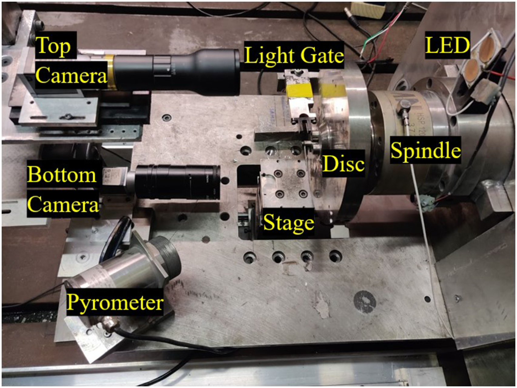
A stroboscopic imaging system is utilised to capture images of the blade after it wears the abradable material. The system includes a camera and an LED which are controlled through use of a signal delay board; the LED is timed to the rotation of the blade through use of a light gate. The stroboscopic system is described in detail in Ref. [17]. Between the abradable sample and microscope stage, a dynamometer is present; additionally, a pyrometer is pointed towards the centre of the rub area. The instrumentation incorporated in the test setup allows constant monitoring through the test for rubbing forces, temperatures and change in blade length.
Additionally to this setup, a lower camera (Basler Ace acA1600-60 gm Monochrome GigE) is used to capture images of the abradable sample side profile throughout the test. LEDs are positioned appropriately in front of the sample to allow sufficient lighting of the sample, and are controlled through a signal delay board to ensure coherence with the blade rotation. This setup allows for further Digital Image Correlation (DIC) processing, calculating strain in the foam as the blade interacts with it; the schematic is shown in Figure 2. Schematic to show camera set up for DIC technique.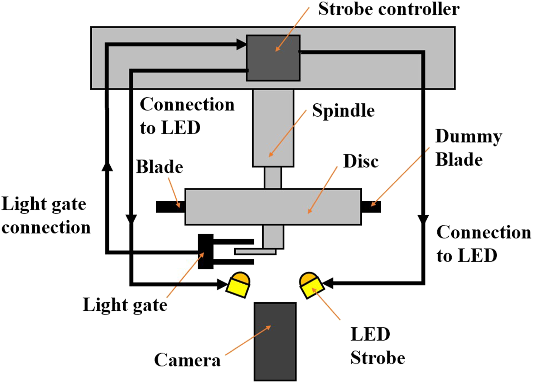
All the abradable samples are tested under the same blade tip speed of 100 ms−1. However, varied incursion rates have been chosen, and are 0.02, 0.2 and 2 μm/pass, and cover a range of engine operation conditions. 17 0.02 μm/pass is a common engine representative incursion rate often seen in previous studies; the maximum reflects engine pass off conditions, and minimum reflects the lowest closure rates in-flight. 23
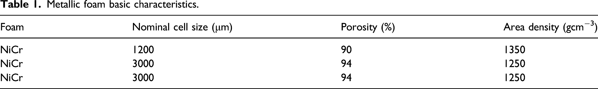
Metallic foam basic characteristics.
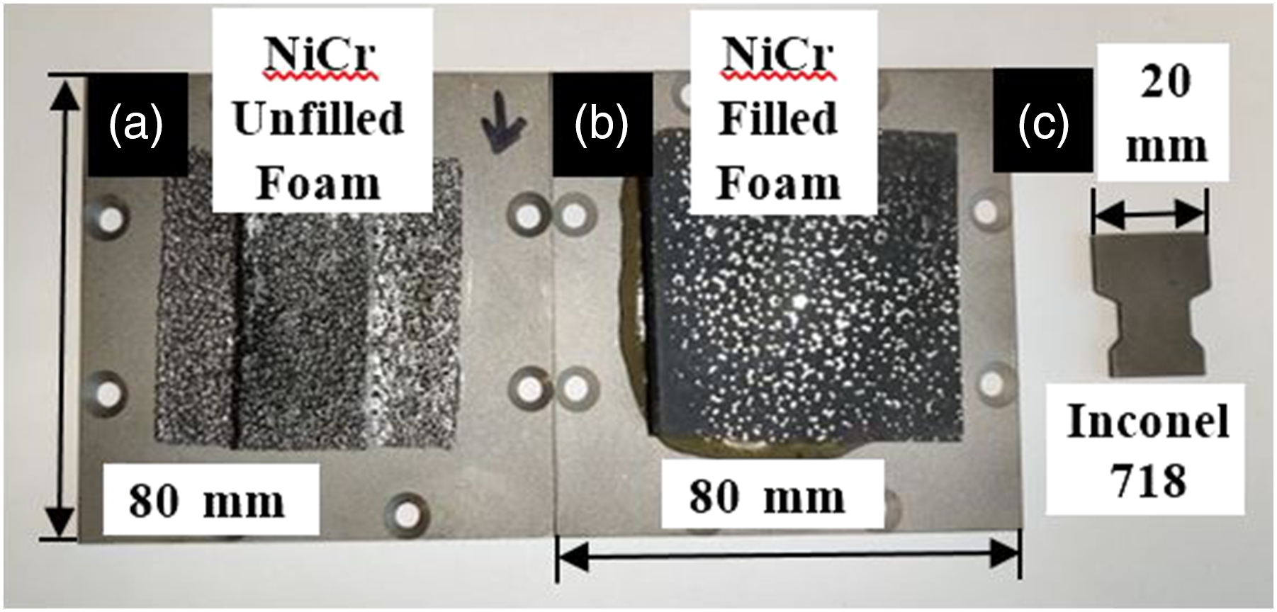
Samples including dimensions and size.
Test matrix.
Standard processing techniques for data analysis of force and temperature have been used which is explained in detail in Ref. [17]. DIC techniques allow investigation into the material mechanical behaviour during the test; this makes use of a different analysis approach. This process aims to obtain a strain field present within a specific region of interest for a material which is undergoing deformation. Images are captured of the material as it deforms and are input into a 2D Digital Image Correlation MATLAB software. 24 This method uses one-to-one correspondence between material points within a reference image and following images and configurations. Subsets are chosen from a reference image to determine respective locations within the current configuration or image; this is described in more detail in Refs. [24,25].
Force data is captured as text files in small time increments over the entire test; each file consists of a few passes of the blade. It is in turn seen that after each pass the force does return to zero since the system is periodical; however, for better visualisation of the data, the maximum force value is extracted and used to show the force progression throughout the test thus with the maximum plotted at a given rub length. This way of processing force data is described in more detail in Ref. [17].
Results
Three comparisons are made for this work on foams which in combination can help provide insight into the wear mechanisms and behaviours. These three comparisons include pore size of unfilled foams, filled and unfilled foams as well as incursion rates.
Unfilled foams–effects of pore size at low incursion rate
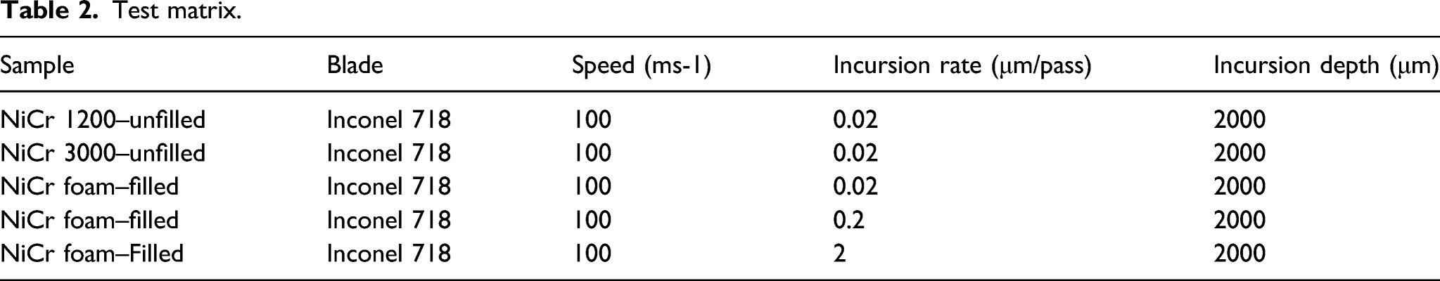
Figure 4 shows results from the test for small cell size (1200) NiCr foam, and at incursion rate of 0.02 μm/pass, it shows characterisation of the blade and abradable as well as forces experienced during the test. Conversely, Figure 5 shows results for larger cell size (3000) NiCr foam under the same testing conditions. Figures 4(d) and (e) and 5(d) and (e) indicate that for open cellular structures a significant amount of blade wear is observed; this is seen for both foams in the optical images to identify the severity. The depth of blade wear can be approximated to be 900 μm for NiCr 1200 and 400 μm for NiCr 3000; larger pore size is seen to be less; however, the test duration till fracture is significantly shorter. Further, this sample fractured and broke after the first 1000 m of rub length due to rapid release of energy from the system through breakage and loss of metallic ligaments due to the fact the foam is unfilled. If the test is repeated, the same result would be expected as there is no load transfer present and the energy will release in the same way, leading to sample rupture and delamination. Hence, a repeat was not performed as the outcome was a function of the material. For larger nominal pore size, there is more severity to the amount of blade wear that occurs which is a major concern which needs to be addressed and will be fully detailed in the discussion. A-H showing examples of blade (a) and abradable (b) samples, force, temperature and blade length change (c), optical post-test blade wear (d,e), SEM blade tip surface (f), stereoscopic image of abradable post-test (g) and optical image of blade tip surf (h). A-H showing examples of blade (a) and abradable (b) samples, force, temperature and blade length change (c), optical post-test blade wear (d,e), SEM blade tip surface (f), stereoscopic image of abradable post-test (g) and optical image of blade tip surf (h).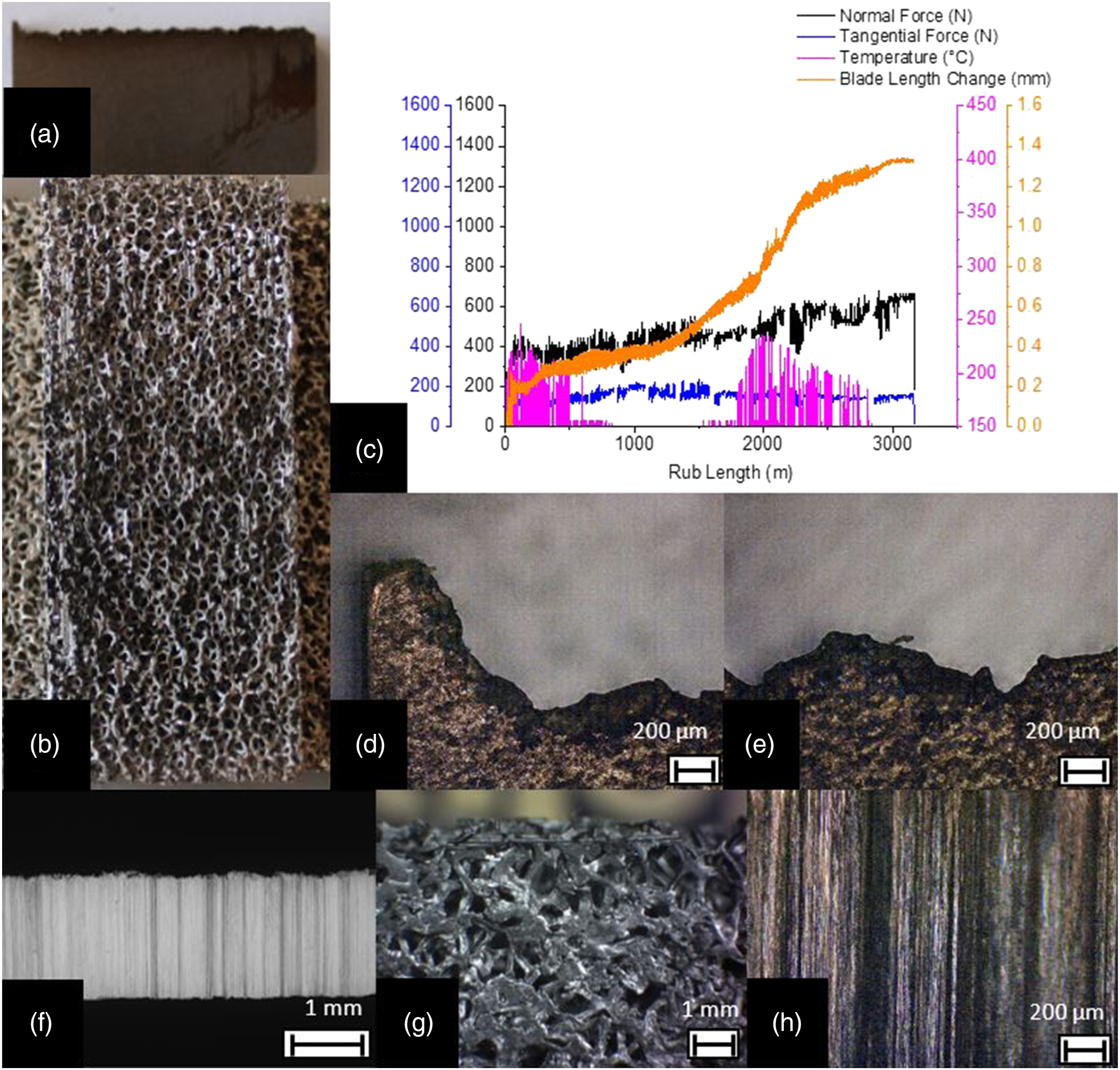
For both abradable samples due to the structure of the foam having open cell formation, the areas where metallic ligaments exist cause ridges to form within the blade when worn. SEM and optical images show these ridges. Due to larger struts and nominal pore size in NiCr 3000, the ridges formed are larger in width compared to that of NiCr 1200 as shown in Figures 4(h) and 5(g) and (h). Figure 4(g) shows the compaction and compression that the metal foam experiences during the test; many of the open cellular regions have fractured and are compacted together.
The rubbing forces for small and large nominal pore size are shown in Figures 4(c) and 5(c); the tangential force experienced can be seen to be greater for a larger nominal pore size. The metallic struts are larger as seen in Figures 4(b) and 5(b) and thus require more energy to remove it; for smaller pore size, the relative metallic struts are smaller and therefore less energy is needed to break and fracture these from the rub surface. The normal force for NiCr 3000 is greater in comparison to NiCr 1200; this would imply less compression and more violent wear of the two components. A smaller normal force for NiCr 1200 indicates that it is easier for the ligaments to plastically deform out of the way and compaction of the abradable material occurs; this is due to the energy being absorbed upon impact by the metallic struts within the top rub surface or breaking earlier.
Observing the rub area seen in Figure 4(b), there are large cavities in the abradable material surface; this is where dislocation and fracture has caused areas to delaminate and break off. From the imaging as well as characterisation, it can be clearly identified that a large amount of material is removed as well as a substantial amount of blade wear. Stress accumulation from the force applied by the blade which localises in the metallic struts is a point of interest which is detailed fully in the discussion.
It should also be noted in the results that the pyrometer measures the temperature based upon the emissivity of the metallic phase over a small region of the blade path. Many times the temperature seems to instantaneously rise as small peaks in Figures 4(c) and 5(c); this is caused by the pyrometer picking up sparks as the blade rubs with the abradable. Furthermore, the pyrometer has a measuring range of 150–1000°C; as a result of this, any temperature below this range is measured as 150°C.
Comparison of filled to unfilled foams at low incursion rate
A comparison is created of the impact fillers have on the breakdown mechanics and behaviour of the metallic foam structures. This is through comparing two separate samples, one of which is NiCr 3000 unfilled foam and the other a NiCr 3000 foam with polyester filler present. The incursion rate for both tests is the same to provide a suitable comparison of how they interact with the blade with and without filler material.
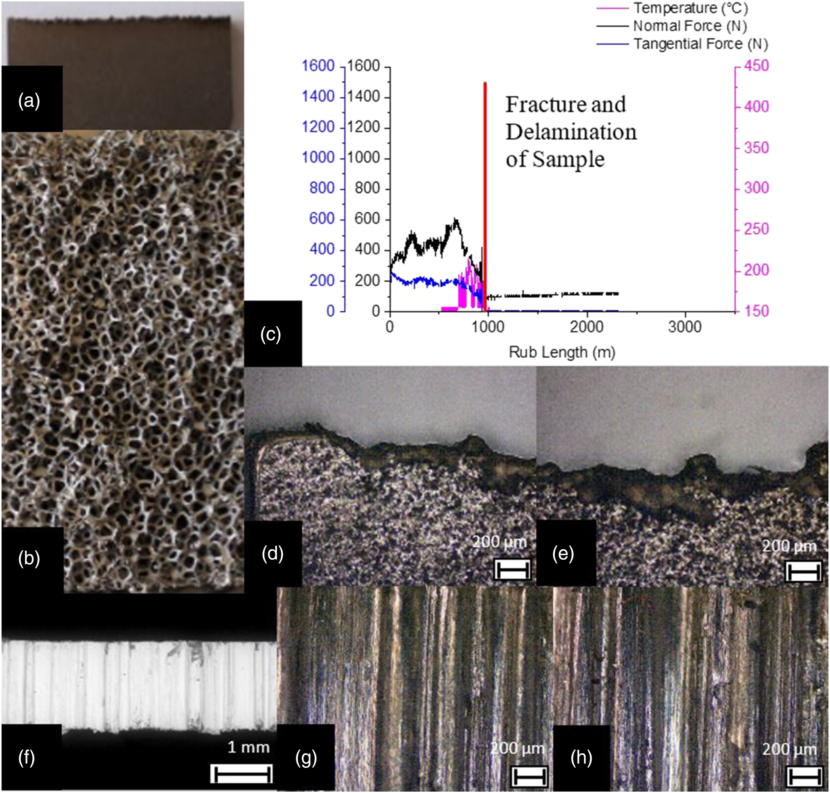
Figure 6 shows the results for a filled foam; it shows characterisation of the blade and abradable as well as forces experienced during the test. The contact surface for in Figure 6(b) shows a large amount of empty pores; the metallic phase is seen to be removed and pulled out during the test. The abradable material shows good compaction upon contact which is a desired property; displacement means that the abradable material becomes concentric to the blade path. A-H showing examples of blade (a) and abradable (b) samples, force, temperature and blade length change (c), optical post-test blade wear (d,e), SEM blade tip surface (f), stereoscopic image of abradable post-test (g) and optical image of blade tip surf (h).
From Figure 6(c), the shear and normal forces recorded are identified to be larger for when filler material is present within the NiCr foam structure; when considering the shear force, the contact surface area is greater and therefore more cutting resistance force exists; the struts are also more supported, meaning they do not deflect. The temperature experienced with filler can peak up to approximately 400°C, for open cell foams 250°C.
Figure 6 shows that with filler material there is little to no blade wear; however, there is more material pickup. The optical images 6D,E show that material pickup exists as a thin layer covering the blade tip; small areas exist where the debris formation is seen as small fragments of filler attached. The SEM image shown in Figure 6(f) indicates the location of the debris pickup and adhesion to the blade. The upper part of the blade is the leading edge; most of the pickup can be seen to occur along the trailing edge of the blade as it passes across the sample.
For an incursion rate of 0.02 μm/pass, a lot of material pull out is experienced. Due to this loss of metallic phase, the remaining material revealed at the surface is polyester filler; polyester filler has a low emissivity and is not picked up by the pyrometer as having any temperature. This in turn causes the sudden drop in temperature seen in Figure 6 where there seems to be no apparent temperature data following this anomaly.
Little blade wear is seen through optical imaging of the blade tip face indicated from Figures 6(g) and (h). A few minor chips and breakdown is from the recast layer which is a result of the manufacturing process. The darker areas illustrate where the filler has adhered onto the blade tip surface.
Effects of incursion rate on filled foams
Incursion rate is varied to identify the effect it has on the breakdown mechanism of filled metallic foams. 0.02, 0.2 and 2 μm/pass are compared and the other testing parameters are kept the same for a suitable evaluation; all three samples are Recemat foam. In Figures 7(c) and 8(c), the force, temperature and blade length change profile during the test for 2 and 0.2 μm/pass, respectively, and the results for 0.02 μm/pass incursion can be seen in Figure 6(c). A-H showing examples of blade (a) and abradable (b) samples, force, temperature and blade length change (c), optical post-test blade wear (d,e), SEM blade tip surface (f), stereoscopic image of abradable post-test (g) and optical image of blade tip surf (h). A-H showing examples of blade (a) and abradable (b) samples, force, temperature and blade length change (c), optical post-test blade wear (d,e), SEM blade tip surface (f), stereoscopic image of abradable post-test (g) and optical image of blade tip surf (h).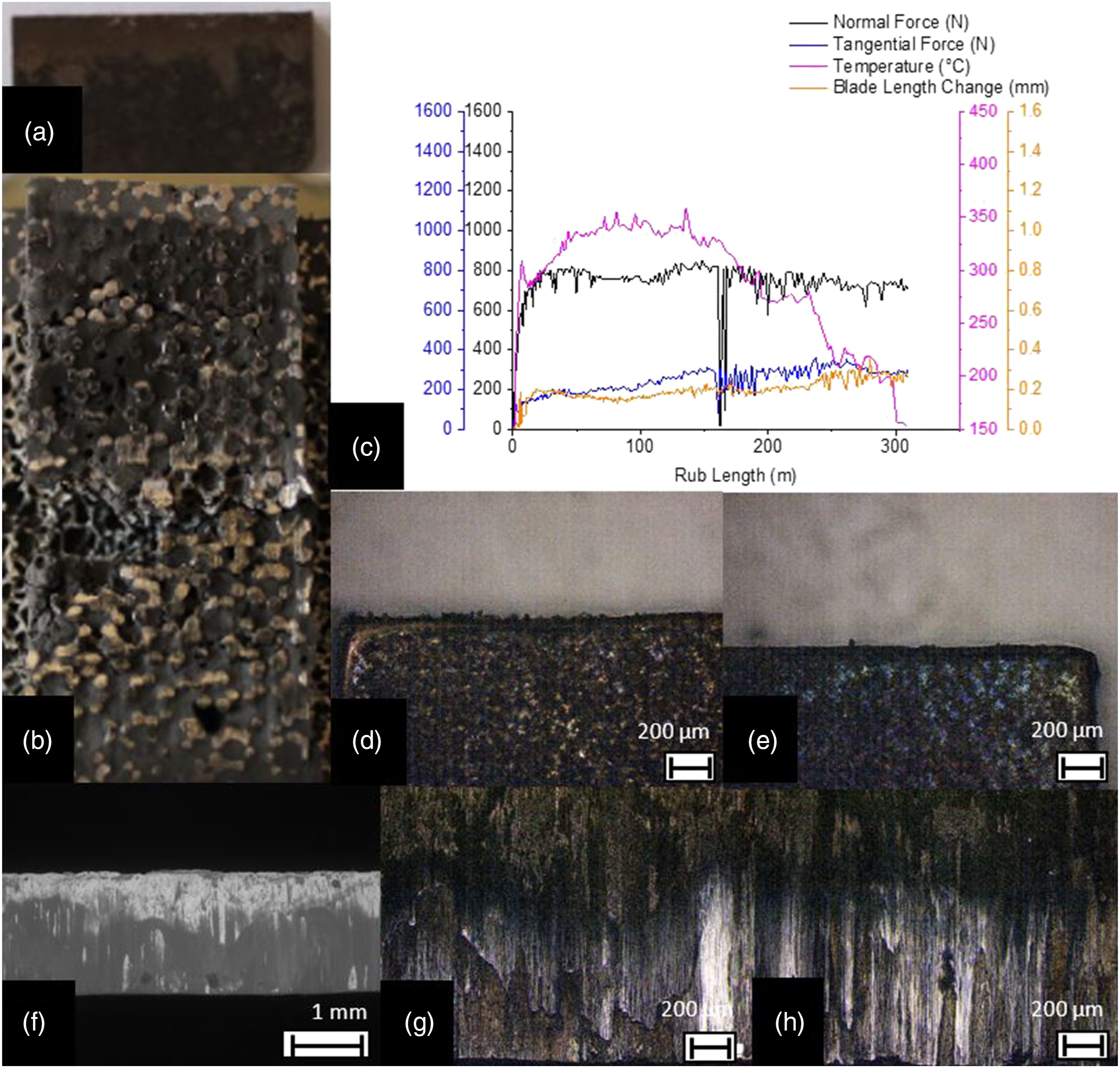
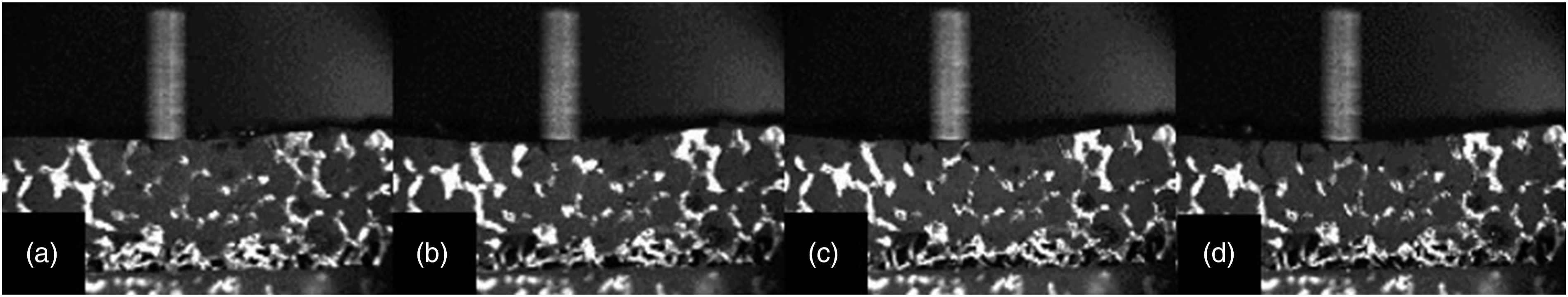
Figure 7 shows the results for NiCr foam at 2 μm/pass; pickup is very low; however, if the incursion rate is decreased by a factor of 10 and 100 to 0.2 and 0.02 μm/pass, pickup starts to increase as shown from the images in Figures 6 and 7; this is seen on the blade tip surface. At higher incursion rates, the rub surface has a smoother morphology with less material pull out. The average and maximum forces acting on the abradable sample are very similar between the tests in the shear and normal direction; however, the wear mechanics and final morphology are significantly different. A main point of discussion is why the variation in morphology is achieved with different incursion rate.
The particle adhesion is more evenly distributed for smaller incursion rates such as 0.2 and 0.02 μm/pass, where the optical images in Figures 6(d) and 7(d) show that the debris pickup is a more uniform layer spread along the blade surface and the particle size is relatively consistent. However, as incursion rate is increased to 2 μm/pass, from Figures 8(d) and (e), it is identified that little material adhesion occurs with incontrollable location and size of debris formation.
Material pull out of the filler phase from the metallic phase is a phenomenon that has been seen to occur for filled foams; this phenomenon is more severe at lower incursion rates. This is an issue that requires further investigation, as large amounts of material pull out means that there is an uneven sealing surface which is undesirable. As the filler material is softer in comparison to the metallic phase, and as a shear force is applied, the filler phase will loosen; this reveals the metallic phase from the top surface allowing the blade to pass and remove it easily. Figure 9 shows a series of images where the material is pulled out of the top surface and the evolution of how it occurs. This process is most apparent at lower incursion rates as energy input is low and often several passes are required to remove a ligament. Evolution of material pull out phenomenon captured by bottom camera for recemat 0.02 μm/pass incursion rate.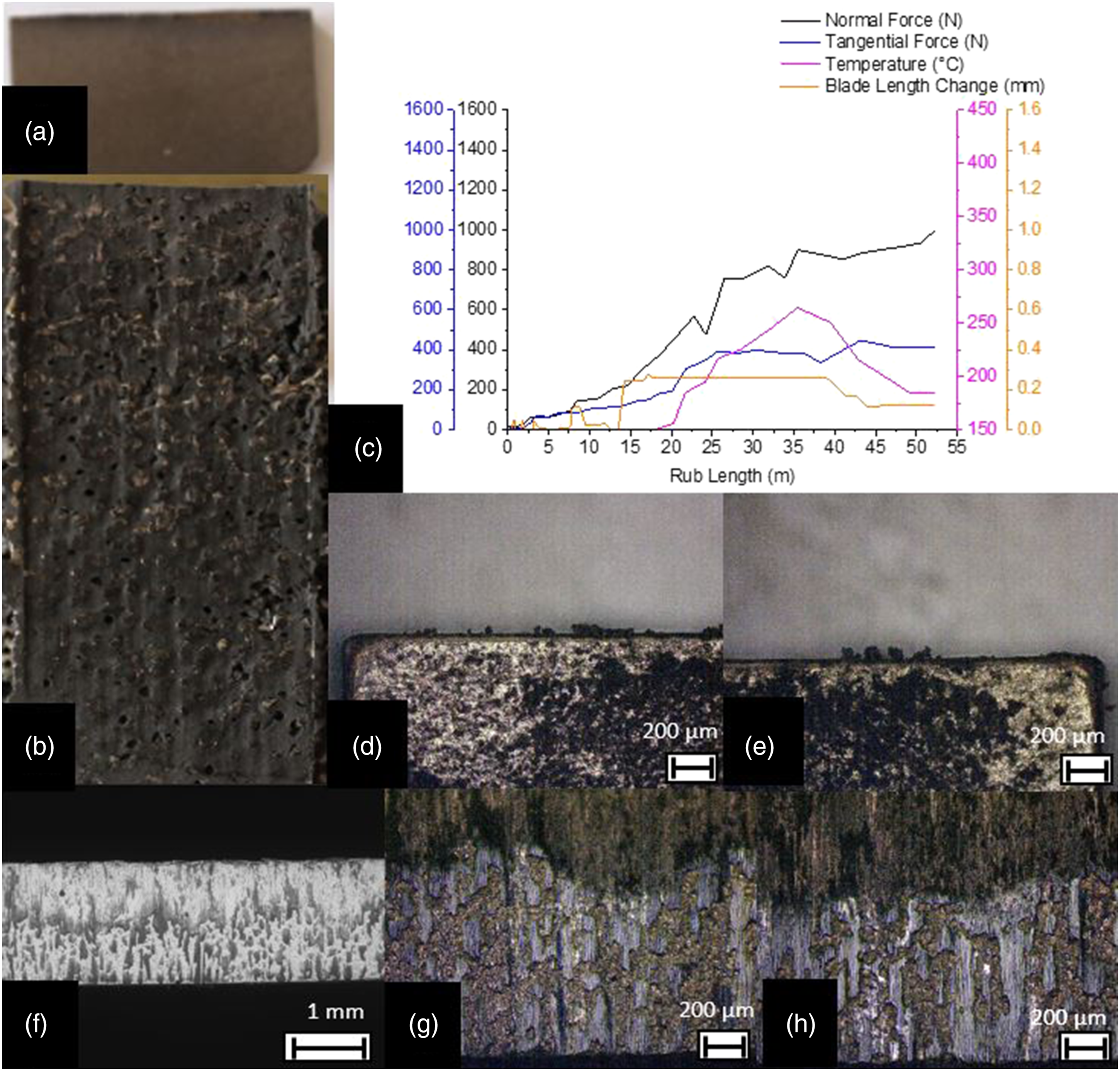
At faster incursion rates, more damage is seen to the recast layer along the blade tip as shown in Figures 8(g) and (h) in comparison to Figures 6(g) and (h); at faster incursion rates, there is more energy entering the system upon contact between blade and abradable sample. From the post-test characterisation seen in Figures 6(b), 7(b) and 8(b), faster incursion rates create a smoother wear surface as well as less material pull out as clear fracture of the ligament with removal of the filler is more likely.
Discussion
As highlighted, further analysis of the abradability of foams is required; this discussion includes the breakdown mechanics and deformation upon interaction between the blade and abradable analysed in more detail. A comprehensive understanding is needed to design the best structure and composition for consistent abradable performance. There are three main points of discussion which include effects of pore size on unfilled foams, impacts of filler added to open cell foam structures and effects of incursion rate.
Unfilled foams–effects of pore size at low incursion rate
As noted previously, significant blade wear was observed for the unfilled foams. The reason behind this wear can be investigated by further processing the images captured of the foam by using a DIC technique to look at how strain is generated by specifically looking at compaction of the surface.
For the larger foams, significant fracture occurs at the surface with a compactive built up layer starting to occur before material ultimately breaks away, and bulk densification of the material is small and more fracture occurs. Given all occurs within the locality of the surface, surface high forces and blade wear are observed. Comparing now the DIC for the finer foams, it is seen that less compaction occurs and more fracture occurs on a strike by strike basis, meaning that lower forces occur and the material does not wear the blade as much; however, this is still enough for some wear. For unfilled foams, the stress and strain localisation in the top rub surface implies a lack of energy absorption and transfer. Figure 10 shows a series of images with the DIC processing overlayed showing the localisation of strain accumulation within the top contact surface. Evolution of strain localisation within the top rub surface for NiCr Foam 1200 0.02 μm/pass.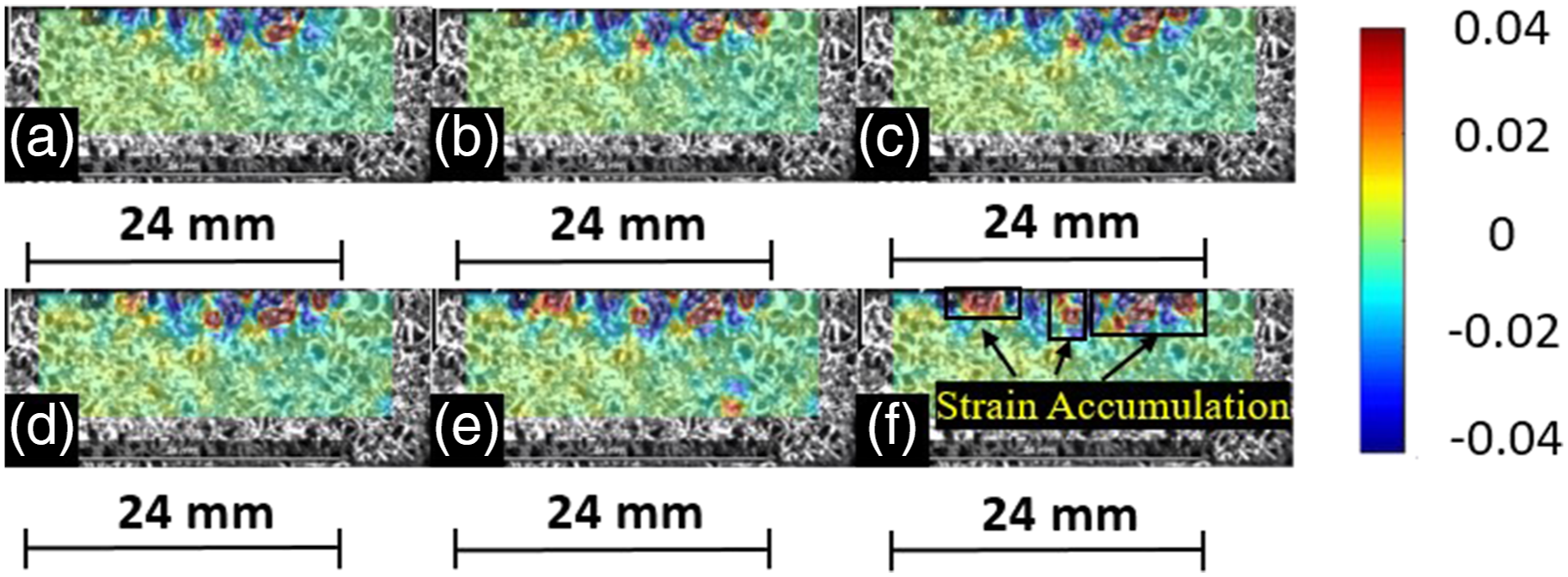
Significant strain localisation and accumulation in the top rub surface indicate that blade wear will always occur, as the metallic foam is NiCr composition and has relatively high hardness, and when subject to shear force, this can require a large amount of force to remove and so wear into the blade is a result of this.
It is also interesting to note that the strain accumulation can be seen to vary depending on position within the arc of contact. For example, in Figure 10, the strain accumulation can be seen to amass in two main locations. Towards the left side where the blade first enters contact, strain accumulation can be seen, and similarly at the exit of contact. This may well be due to the shock loading of entry and exit when the blade interacts with the sample much in the way seen for a machining insert or tool flute in milling. 26
The locations where stress and strain build up are clearly pinpointed within a larger pore size structure since the metallic struts can be identified more easily as shown in Figure 11. Open cellular foam structures always have two outcomes, significant wear of the blade or significant wear of the abradable. For large pore size, the number of interconnecting struts within the base is significantly less in comparison to a smaller pore size foam; if any of the major ligament support structures break and get removed, the structural integrity becomes weak and ultimately leads to break away. Evolution of strain accumulation in the bottom section of the abradable for NiCr Foam 3000.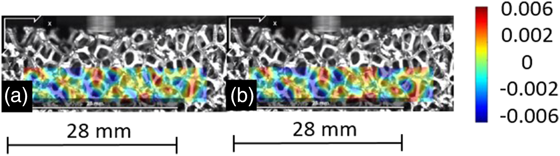
As such, the pore size directly influences which component wears and which is damaged between the blade and abradable. With larger nominal pore size, the metallic struts are larger in size; these metallic struts are stronger individually in comparison to a small nominal pore size metallic foam. The strut density, however, for larger nominal pore size is significantly reduced; in turn, the spatial differences are larger between interconnecting struts; this promotes a fracture mechanism where the joining struts break apart. More violent wear is thus noted for the larger nominal pore size since less compaction occurs. Conversely, for a smaller nominal pore size, the fracture occurs only at the surface and more densification and compaction is noted as seen in Figure 4(g); this results in wear of the blade and no transfer within the abradable material. For unfilled foams of smaller size, compaction can occur as well as violent wear. It is not feasible to have open porous structures due to the excessive blade wear; this will cause low performance and minimal component lifetime as well as large amounts of debris formation in the form of fractured large metallic ligaments.
Impact of filler to open porous NiCr foam
Conversely, for filled foams, blade wear did not occur; for filled foams, the behaviour is broadly similar at all incursion rates; in this section, the overall mechanics of filled metallic foams is discussed before moving onto the next section to consider subtlety in response with incursion rate. As filled foams exhibit better cutting with minimal to no blade wear, DIC is used to further understand the results.
When a filler is present, it can be seen that two things occur. Firstly, it allows a degree of bulk load transfer to occur where the abradable is able to deflect and move away from the incurring blade; additionally, the filler also holds the ligaments in place where a component of the blade’s energy also leads to ligament fracture. These two mechanisms happen together where a fraction of load transfer and a degree of breaking occurs, and combined mean that a compactive layer no longer occurs at the surface and blade wear can be avoided.
Filler material is therefore useful to help absorb and dissipate energy from the blade impact, and the main role of DIC processing is to identify failure regions of high stress and understand how the filler impacts the behaviour and response of the metallic foam structure. This highlights how fillers are important due to their capability to promote load transfer. A good example of this load transfer is shown in Figure 12 for an incursion rate of 0.02 μm/pass where it can clearly be seen that the filler absorbs the energy and transfers the load through the sample, and repetition helps reduce the breaking of the metallic phase by absorbing the energy upon impact of the blade. Evolution of strain distribution in the abradable sample for NiCr – Filled Foam 0.02 μm/pass.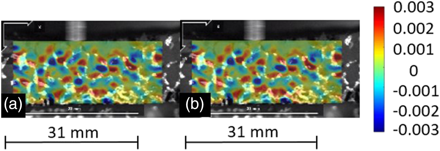
Areas of large strain and buckling occur where small regions of filler are surrounded by neighbouring metallic struts/ligaments, and a large impact force from the blade contact can cause the metallic phase to loosen within the entire structure. Without the presence of filler material, the strain accumulates in such areas. The filler helps to reduce the severity of this phenomenon; however, long-term solutions will need to be implemented to avoid or control the filler distribution. Figure 13 shows a good example of where the effects of open pores and uneven distribution or lack of filler is present, leading to large strain accumulation followed by breaking away and formation of large cavities. This highlights the importance of filler evenly distributed within the metallic foam structure. Evolution of strain build up when lack of filler for NiCr – Filled Foam 0.02 μm/pass.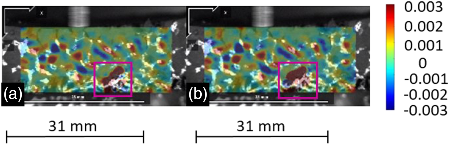
As such, a good load transfer mechanism requires an evenly, well-distributed amount of filler in the NiCr metallic foam structure. Figure 13 shows an example of where the strain accumulation builds and will ultimately end in fracture and damage to the abradable. The evolution of strain accumulation can be captured in these two frames; in these circumstances, this can cause delamination of the abradable sample. This clearly highlights the importance of the filler to better promote the load transfer mechanism to prevent blade wear and significant damage to the foam.
Cutting at various incursion rates
Moving on to consider the effect of incursion rate on filled foams, the post-test rub surface observed through macroscopic techniques in Effects of Incursion Rate on Filled Foams effectively shows this. Higher incursion rates promote more load transfer and more actuation of these positive mechanisms. Noted in the previous sections, load transfer and ligament fracture were observed for all the filled foams to a degree; however, there were some subtle variations observed with incursion rate.
Chips and small shallow cavities are identified in the rub surface for smaller incursion rates; this is due to a lack of energy input to the system and more strain accumulation within the surface compactive layer. At the lowest incursion rate of 0.02 μm/pass, there is a reduced amount of load transfer and actuation of this mechanism; this ultimately leads to some material pull out of the metallic ligaments.
The filler material is relatively soft in comparison to the metallic phase and blade. The longer test duration time for slower incursion rates such as 0.02 μm/pass means the abradable sample has taken more impact hits from the blade. The filler phase can easily loosen up and dislocate to reveal the bare metal ligaments which are thus removed as the blade impacts further. This is mostly seen at slower incursion rates which is shown by the rub surfaces in Figures 6(b), 7(b) and 8(b).
Conclusion
This study of metallic foams has been performed to investigate the wear mechanisms and breakdown behaviour during rub tests between the abradable sample and blade. The abradable samples are tested under varied incursion rates of 0.02, 0.2 and 2 μm/pass for recemat and polyester metallic foam structures. Tests performed at higher incursion rates were found to cut better with less adhesion formation along the blade tip face; however the uniformity of this adhesive layer is very poor in comparison to lower incursion rates. Further testing will help to confirm this and provide some more understanding of how the adhesion forms and how this impacts the abradable structure.
In unfilled foams, larger pore size results in more severe blade wear and abradable damage; some compaction is seen within smaller pore size; however, it is still a significant amount of damage to both components. Filler materials are able to prevent large strain accumulations within the metallic phase of the foam abradables; this helps the foams to perform suitably when worn with minimal blade wear and good compressive behaviour. The load transfer mechanic capability for fillers helps to transfer energy and distribute this evenly within the abradable structure; DIC imaging shows great contrast and comparison between filled and unfilled foams to identify where the strain accumulation occurs, and how this correlates to material behaviours such as fracture and crack propagation.
These results show that knowledge of the wear mechanisms in this series of rub tests provides initial insight and understanding of the rubbing forces and wear properties of metallic foam structures. Further work from this group will focus on understanding the actuation of these wear mechanisms and how to take advantage of these which is essential for investigating the feasibility of metallic foams; also a good consideration would be to use filler materials that can withstand higher operating temperatures.
Footnotes
Declaration of conflicting interests
The author(s) declared no potential conflicts of interest with respect to the research, authorship, and/or publication of this article.
Funding
The author(s) received no financial support for the research, authorship, and/or publication of this article.