
Abstract
The paper presents a design of a small-scale centrifugal compressor to match the performance of up to 20% larger diameter compressor in order to meet the demands for a higher mass flow rate and wide operating range for turbocharging applications. This development considers the 44 mm diameter impeller design involving transonic blading and state-of-the-art blade features. In the course of design, the investigation on the inducer blade angle
The performance of the present compressor stage is analyzed with computational fluid dynamics simulations and experimental tests. The comparison of the predicted and measured results of the 44 mm compressor stage shows a good agreement for overall performance. Besides, the 44 mm compressor stage having the most efficient diffuser width and enlarged volute A/R ratio shows a good overlap of performance with approximately 20% larger diameter (52 mm) compressor stage performance. This development demonstrates that the impeller with state-of-the-art design features are likely to contribute to enhancement of the compressor performance.
Introduction
Centrifugal compressors are compact, economical, and reliable for a single-stage application and have been extensively used in turbochargers. In addition, downsized vehicle engines prioritize smaller turbochargers due to packaging constraints which limit the compressor exit diameter. In advanced vehicle engines, it is necessary that turbochargers deliver the required boost and larger mass flow rate to support efficient combustion and meet engine emission standards. In this course of action, a smaller diameter compressor impeller needs to have a higher flow capacity which can be satisfied by increasing the inlet or inducer diameter.1,2
In such a scenario, the blade inducer plays a vital role in determining the compressor performance as it has been demonstrated that a required flow and stability in the compressor can be achieved with a tailored transonic inducer. 3 However, a higher inducer or inlet diameter leads to supersonic Mach number at the blade inlet alongside the relative Mach number in the range of 1.2 to 1.4 at the inducer.4–6
In principle, the transonic inducer in the impeller experiences a significant loss due to a shock wave and its interaction with tip clearance flow. This loss accounts for a minimum of 10% of the total loss,1,5,7 and results in the aerodynamic performance worse than subsonic compressor impellers. 8 Thus, designing the transonic compressor with state-of-the-art methodology is necessary to alleviate the shock wave loss.
Hazby et al. 6 studied the compressor impeller with the inlet relative much number of 1.4 with free-form inducer. They showed that the impeller with the forward-swept blade leading edge near the casing reduces the loss due to change in shock structure, however, decreases the natural frequency of the blade in comparison to the baseline impeller blade. In another case, with the barrelled forward sweep of the blade leading edge along with the higher chord length at the blade mid-span, the impeller showed better performance similar to forward-swept blade impeller but with better mechanical properties. Where they attributed this performance improvement to the non-linear distribution of the throat area across the blade span of the swept impeller.
He et al. 9 investigated the effect of the blade sweep on the performance of a transonic centrifugal compressor while sweeping the blade shroud chord by −25 to +25 degree. They observed that the blade sweep affects the choke mass flow rate, pressure ratio, and efficiency by around 1% and showed that impellers with higher front blade-loading have a stronger effect of the blade sweep. They also demonstrated that the blade forward sweep limits the shock strength, tip leakage vortex, and reduce losses in the casing region.
Overall, these recent studies on larger diameter transonic centrifugal compressors demonstrate an appreciable improvement in performance which is attracting the attention of the turbomachinery industry.2,6,8,10 However, the development of a smaller size (<50 mm) transonic centrifugal compressors is hardly witnessed.
The present study focusses on the development of a smaller size compressor with an objective to achieve the performance of approximately 20% larger diameter compressor. In particular, the current work is related to the development of the 44 mm transonic impeller with wide operating range in order to attain the performance of the 52 mm compressor.
Compressor stage design specifications
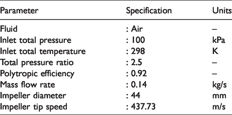
The specifications for the preliminary design of a single-stage centrifugal compressor are described in Table 1. These design specifications involve pressure ratio and mass flow rate from a targeted performance of the 52 mm diameter compressor stage used in GT2052 turbocharger. 11 The design is constraint in terms of impeller outlet diameter, hub diameter, and impeller axial length while following best practice design guidelines.
Compressor stage design specifications.
Preliminary design of the centrifugal compressor
The preliminary design method proposed by Aungier12 is adopted to determine the geometrical dimensions for each component in the compressor stage. An objective here is to achieve a higher mass flow rate and higher flow operating range for a given range of pressure ratio and adiabatic efficiency. Notably, the blade exit angle in the present design is computed by solving equations (1) and (2) iteratively.
12


Here, tip distortion factor 


Here,
The blade work input 


Furthermore, with assumed value of inlet mean relative flow angle 
Similarly, the blade angle at the hub and shroud is computed by initially determining the meridional velocity at respective locations as presented in equations (10) and (11).


Here,
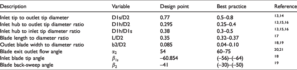
Moreover, precautions have been exercised to set out the design point that can provide a design output consistent with design practice and meet the design objectives. The best practice limits and design point values for the present design are listed in Table 2. Notably, these best practice ranges have been thoroughly investigated for various industrial applications while keeping in mind the trade-off between aerodynamic performance and mechanical integrity of the centrifugal compressor impeller.
Compressor design range and design point value.
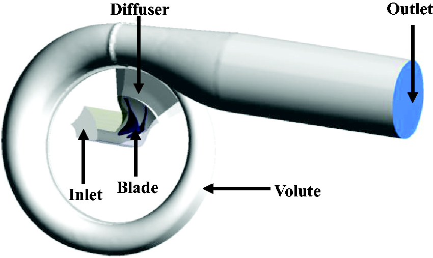
Ideally, kinetic energy at the outlet of the impeller accounts for 30 to 40% of the total energy.22–24 To convert kinetic energy into static pressure, a vaneless diffuser is incorporated in the compressor stage which also aids to achieve a wider operating range in compressors.24–27 In addition, a pinch is applied at diffuser inlet which likely to have a favorable effect on the compressor stage performance.28–30 At any given rotational speed, the compressor performance characteristic is limited by surge and choke point. In this design, the surge is defined as a sudden drop of pressure ratio for a small reduction in mass flow rate which occurs at the left-hand side of the performance curve. Likewise, choke point on the right-hand side of the performance curve is associated with the maximum swallowing capacity of the compressor where decreasing the pressure ratio beyond this point does not alter the mass flow rate, however, results in poor efficiency. The final layout of the compressor stage alongside the basic impeller dimensions are portrayed in Figure 1. With a zero swirl at the blade inlet, the resultant velocity triangles for the present design is shown in Figure 2. The blade rotational speed of 339.12 m/s at shroud and 129.33 m/s at the hub at station 1 in Figure 1 is estimated with reference to the corresponding diameter at inlet and blade outlet tip speed of 437.73 m/s. At the blade outlet, the exit flow angle of 55 degree is estimated along with the absolute flow velocity of 283 m/s into the vaneless diffuser at the design condition.
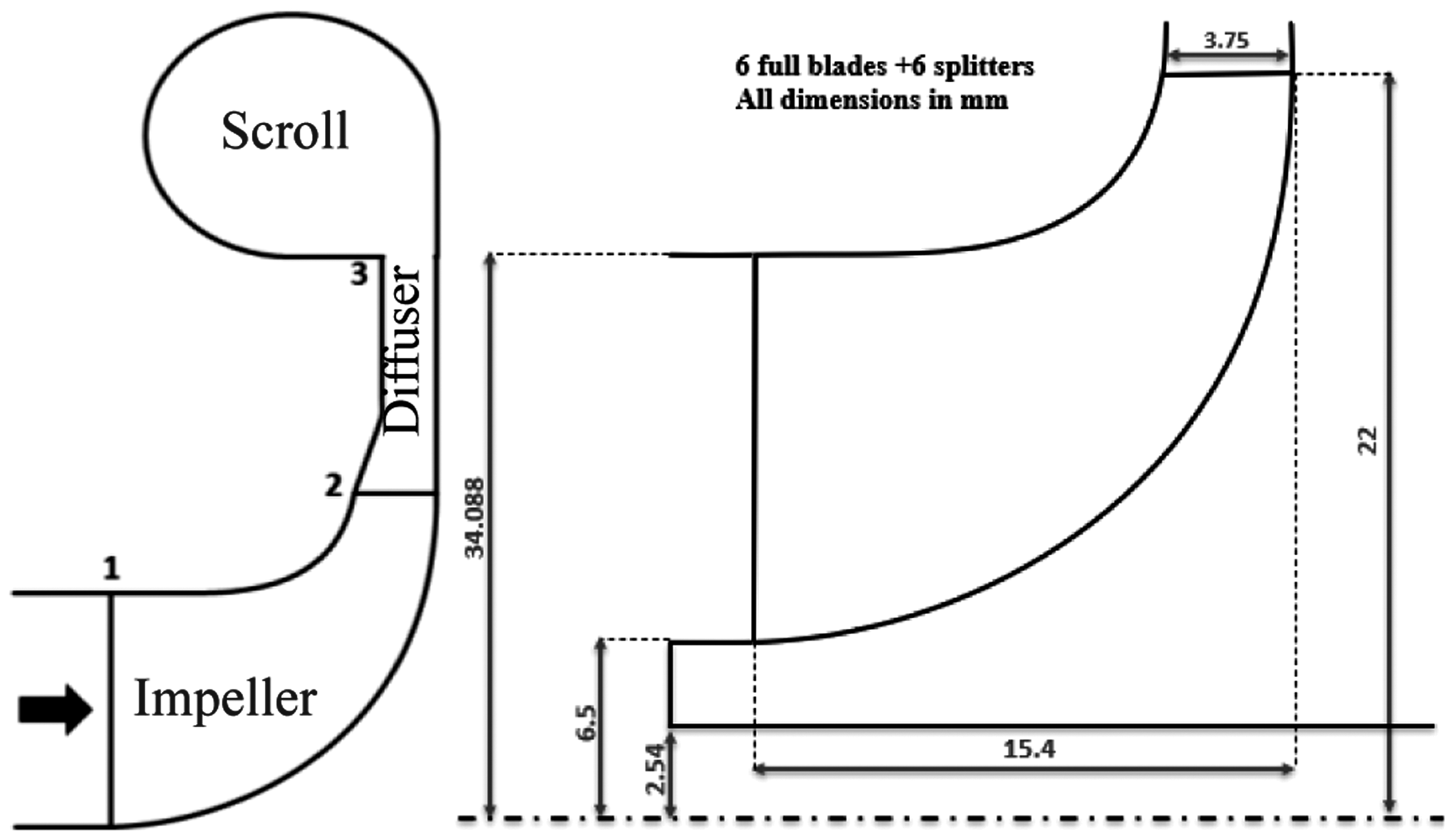
Compressor stage layout with basic impeller dimensions.
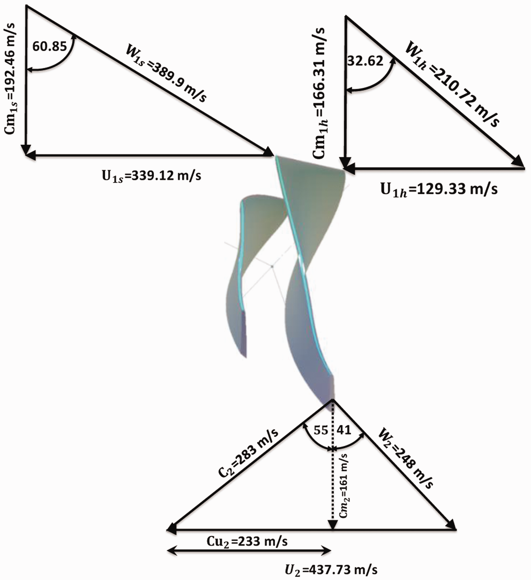
Impeller inlet and outlet velocity triangle.
Three-dimensional impeller design
The impeller blade is constructed using three-dimensional straight-line elements. The compressor impeller hub contour is modeled using the circular arc whereas the shroud curve is constructed using the three-point cubic spline fit curve.
12
The blade angle distribution is crucial in compressor blade design which significantly affects the impeller performance.
31
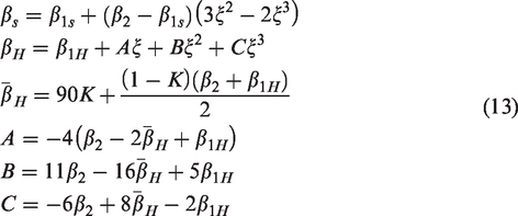
Casey et al.32 and Van den Braembussech33 proposed the blade angle distribution based on the Bezier polynomial and cubic Bezier curve, respectively. However, in the current design, the blade angle distribution is modeled using a correlation proposed by Aungier12 as shown in equation (13). The resulting blade angle and polar angle distribution for the blade is shown in Figure 3 where the blade angle 
Distribution of angle (a) blade angle (b) polar angle.
The magnitude of the lean/rake angle at the blade leading and trailing edge can be managed by manipulating a polar angle difference between the hub and shroud at a respective location.
31
A correlation that can be used to estimate rake angle 
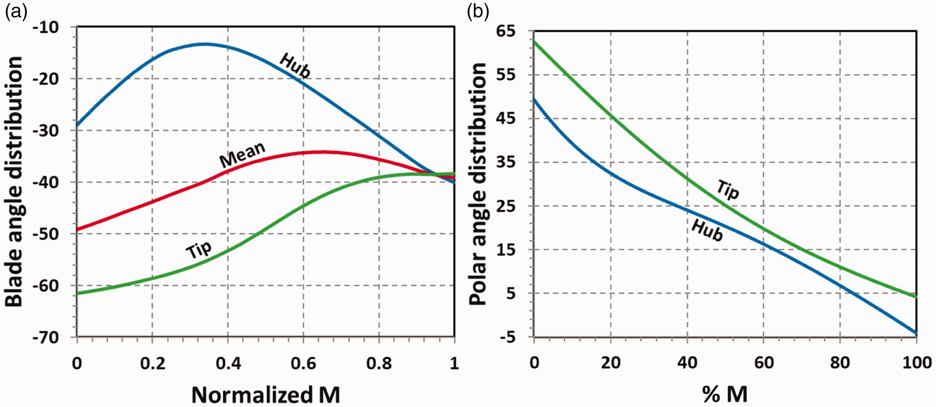
In the current design, the lean angle in the direction of rotation is limited to 15 degrees at the leading edge of the blade to control the shock structure. In addition, it helps in reducing the secondary flow and wake region by creating counter vortices. Moreover, a co-rotation rake angle of 40 degrees is applied at the blade trailing edge to minimize stress in the blade whereas the blade rake angle up to 45 degrees is commonly used in compressor impellers.17,31,36 A pictorial view of the blade lean at the inlet and the blade rake at the outlet can be seen in Figure 4(a) and (b). The blade backsweep has demonstrated to improve the compressor efficiency and operating range, however, it also leads to higher centrifugal stress in the blade. Following the best practice range, the present blade is modeled with −41 degree back-sweep in order to achieve a better operating range and avoid any efficiency drop due to a smaller size and higher speed of the compressor. The overview of the back-sweep angle in the impeller is presented in Figure 4(c).
(a) Blade lean (b) Blade rake and (c) Blade back-sweep.
To facilitate a higher mass flow rate through the blade passage, splitter blades are employed in the compressor stage at the middle pitch location, where the splitter leading edge is placed at 25% of the blade meridional length at the hub and 42% of the blade meridional length at the shroud.
Furthermore, a larger diameter inducer is necessary for a larger flow capacity in the compressor stage. Besides, the inducer in the impeller increases the average static pressure before the full shroud curvature is realized. It also imparts the swirl or tangential velocity to the flow which contributes to set up a static pressure gradient with a higher magnitude of pressure at the shroud and provides a larger throat area to facilitate a larger mass flow rate. However, a larger inducer diameter causes the inducer to encounter with a relative Mach number
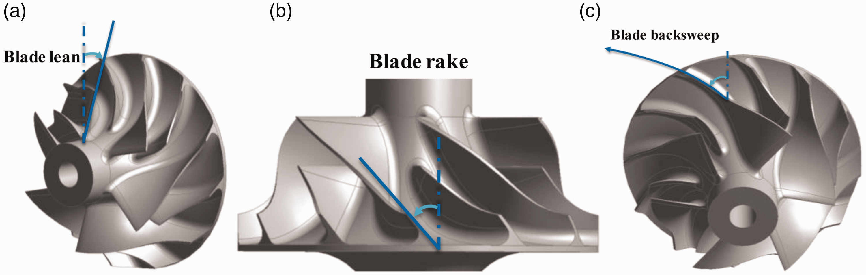
A correlation shown in equation (16) can be used to demonstrate the effect of the blade inlet relative flow angle 
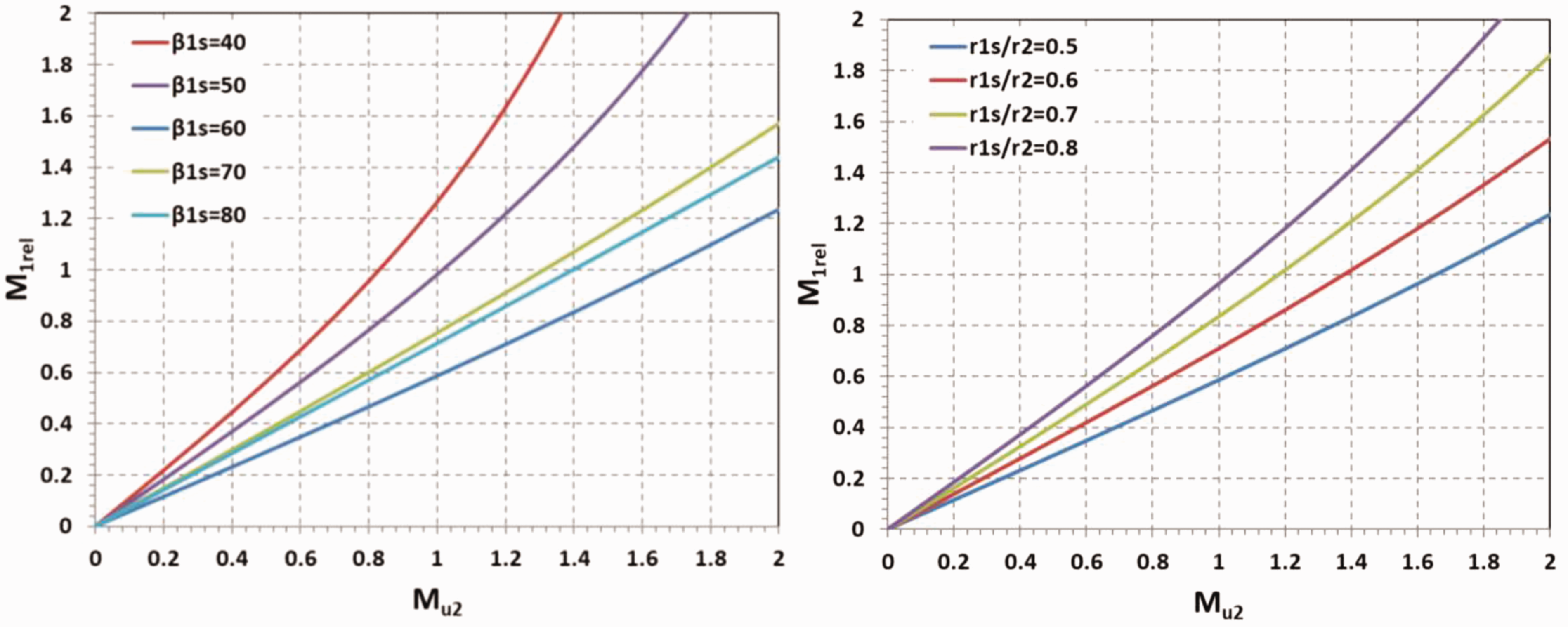
The effect of inlet relative flow angle and radius ratio on Mrel1s.
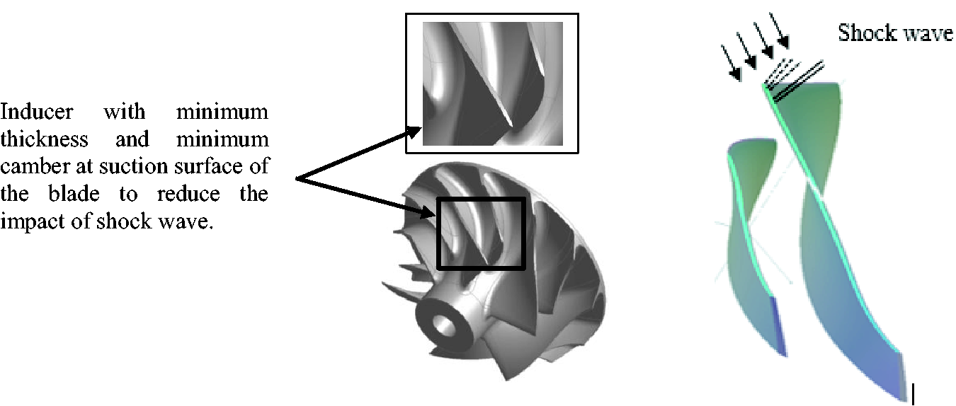
In order to keep losses minimum and attain optimum performance, the inducer tip is designed with (-) 60-degree blade angle and inducer-to-outlet radius ratio of 0.77. Importantly, as the inducer is likely to experience subsonic flow at the hub and supersonic flow at the tip, the inducer is modeled with transonic blading such as minimum camber at the suction surface alongside a smaller blade tip thickness as illustrated in Figure 6. Such design attributes are prone to reduce shock strength and shock losses alongside the flow separation at the inducer.3,10,37,39,40
Blade inducer with transonic flow features.
Notably, the transonic inducer, blade lean/rake, and back-sweep at the blade trailing edge are major contributors in widening the operating range of the compressor. Especially, transonic inducer minimizes the local Mach number, associated shock loss, and flow detachment at the suction surface. The blade lean at the leading and trailing edge of the blade improves the pressure gradient across the span and assists in delaying the flow separation whereas blade backsweep ensures a better operating range. 36 From a mechanical strength perspective, the blade tip is held at a constant thickness of about 1.7% of the blade outlet radius. The hub thickness has been optimized with several thickness distribution profiles as the hub thickness distribution significantly impacts the blade root stress and blade frequencies. 41
Performance evaluation of the centrifugal compressor
The performance analysis of the compressor stage is conducted using the ANSYS CFX commercial CFD software. This code is based on the finite volume discretization approach and solves the three-dimensional Reynolds-Average Navier-Stokes (RANS) equations. 42 These RANS equations are coupled with the turbulent closure k-ω SST model, which is shown to predict accurate results under adverse pressure gradient flows. 43
The computational domain for this steady-state analysis consists of a single blade passage with single sector vaneless diffuser and volute as presented in Figure 7. The single passage domain represents 1/6th of the full impeller and imposed with periodic boundary condition in a circumferential direction. The structured grid generation for the impeller blade and diffuser is accomplished using the Ansys Turbo-Grid module, whilst volute is meshed with an unstructured grid using the Ansys ICEM-CFD package. The steady-state simulations are conducted with a frozen rotor interface between blade and diffuser passage, and stage interface between diffuser and volute domain. The stage inlet is imposed with the stagnation conditions in compliance with the ambient condition (100 kPa, 298 K) and the outlet is set with a variable static pressure condition. All solid boundaries are treated as adiabatic walls with the no-slip condition. The normal blade tip clearance of 0.325 mm, 0.75% of the compressor wheel diameter, and 0.215 mm, 0.5% of compressor wheel diameter is applied to the inlet and outlet section of the blade respectively. 44
Compressor stage computational domains.
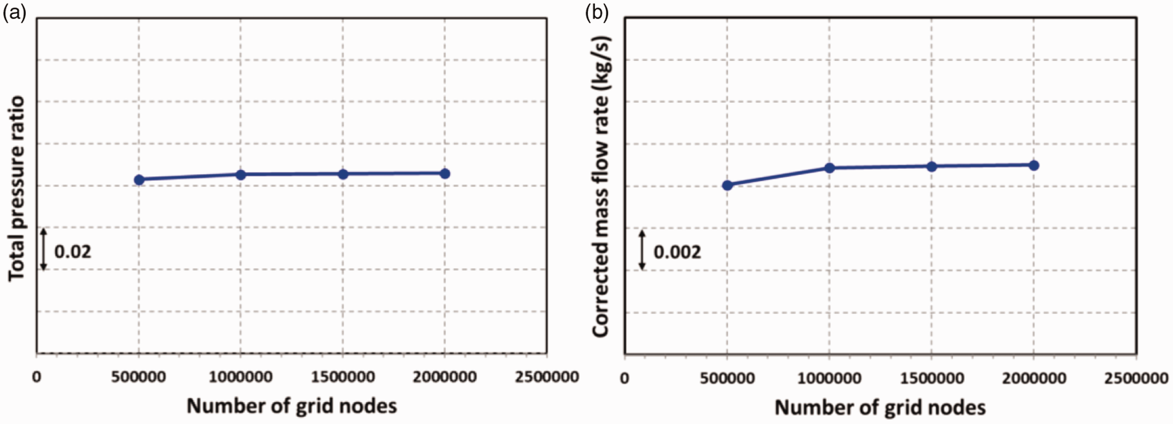
To determine the correct grid size for CFD analysis, a grid independence study is carried out at design condition. It is evident from Figure 8 that the compressor stage performance remains converged from 1 million grid nodes onwards and further refinement of a grid in the compressor stage does not show any performance difference.
Grid independence study for the compressor stage.
Based on a grid independence study, a final grid size in the compressor stage comprises 1 million grid nodes with an additional 0.4 million grid points in the volute domain. A first cell height of 5e-6 m is imposed in the impeller and diffuser mesh, whilst the volute mesh has 15 prism layers on the wall with a first cell height of 1e-5 m to resolve the near-wall flow gradient. An overview of the compressor stage mesh is provided in Figure 9. To resolve the near-wall flow, a non-dimensional first cell height Y+ equals to 1 is attempted on most of the region of the impeller blade. For higher Y+, the simulation is coupled with an automatic near-wall treatment to model the near-wall flow gradient. 42 For all simulations, the maximum residual target of 1e-6 (RMS 1e-4) is considered as convergence criteria. Besides, imbalance in solution less than 1% is ensured to keep the error in solution as minimum as possible.
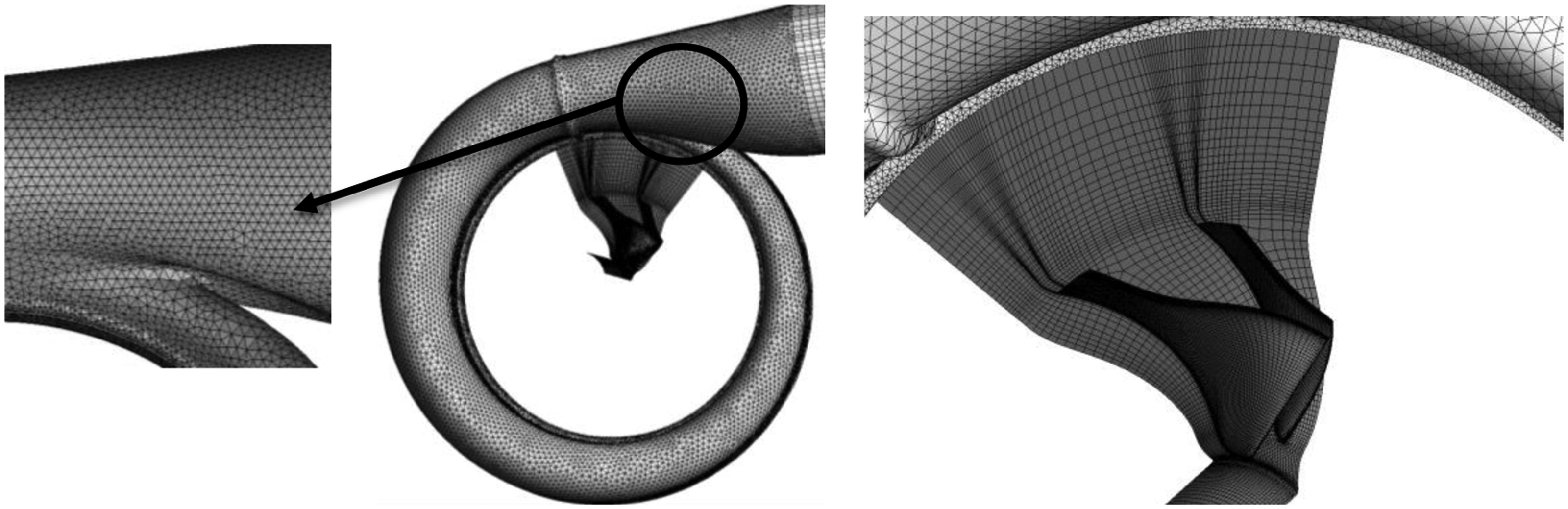
Computational mesh in the compressor stage.
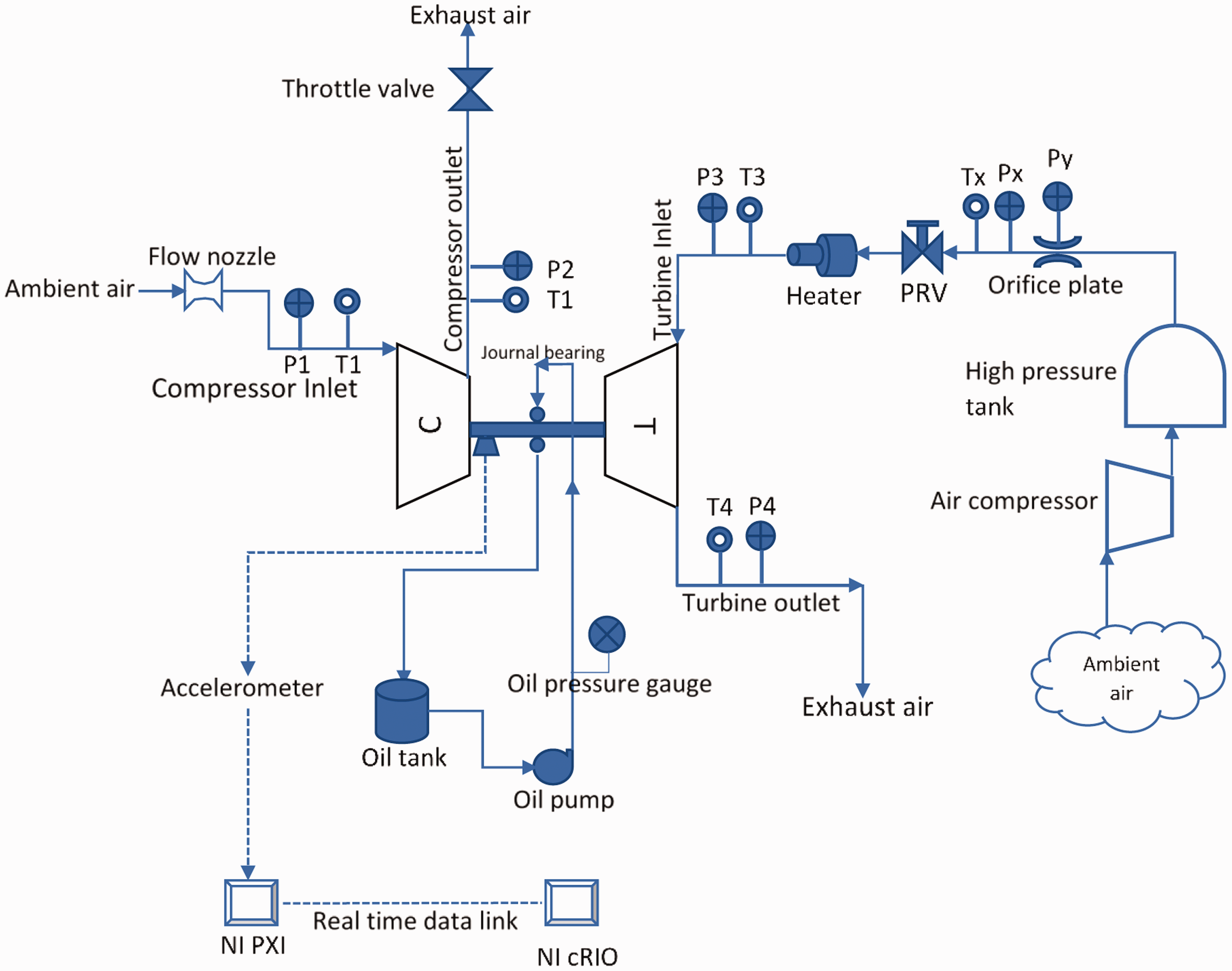
Test rig layout for the compressor.
The experimental test layout for the compressor stage is shown in Figure 10. The test rig consisted of a high-pressure storage tank, electric heater upstream of the turbine, lubrication module for oil-bearing and flow throttle at the compressor stage outlet to modulate the mass flow rate and pressure ratio. The pressure and temperature are recorded with the pressure tap and J-type thermocouple respectively. In this test campaign, the compressor rotational speed is moderated by varying turbine inlet pressure and measured using the accelerometer. The compressor stage mass flow rate in the experiments is measured using the flow nozzle at compressor inlet with a throat diameter of 28.3 mm. A correlation used to measure the mass flow rate is shown in equation (17)45


These experiments are conducted with Garrett GT1544V turbocharger. This turbocharger has been used in 1.6 liters engine passenger cars such as Peugeot, Citrogen, and Ford . For tests, the compressor wheel in this turbocharger is replaced with a self-developed 44-mm compressor impeller and the compressor housing shroud is reprofiled to make it compatible to a new 44 mm impeller tip profile. Moreover, the same compressor housing is scanned using the 3 D laser scanning technology to achieve the three-dimensional surface CAD model and used for computational studies.
The 44-mm compressor stage is tested by supplying a high-pressure flow to the turbine. The performance of the compressor stage is drawn by regulating the throttle valve which results in pressure ratio vs mass flow characteristics. The testing of the compressor stages is limited to 1,50,000 rpm, as testing for higher rotational speeds requires power supply exceeding 30 kW, which was beyond the capability of this test facility.
Results and discussion
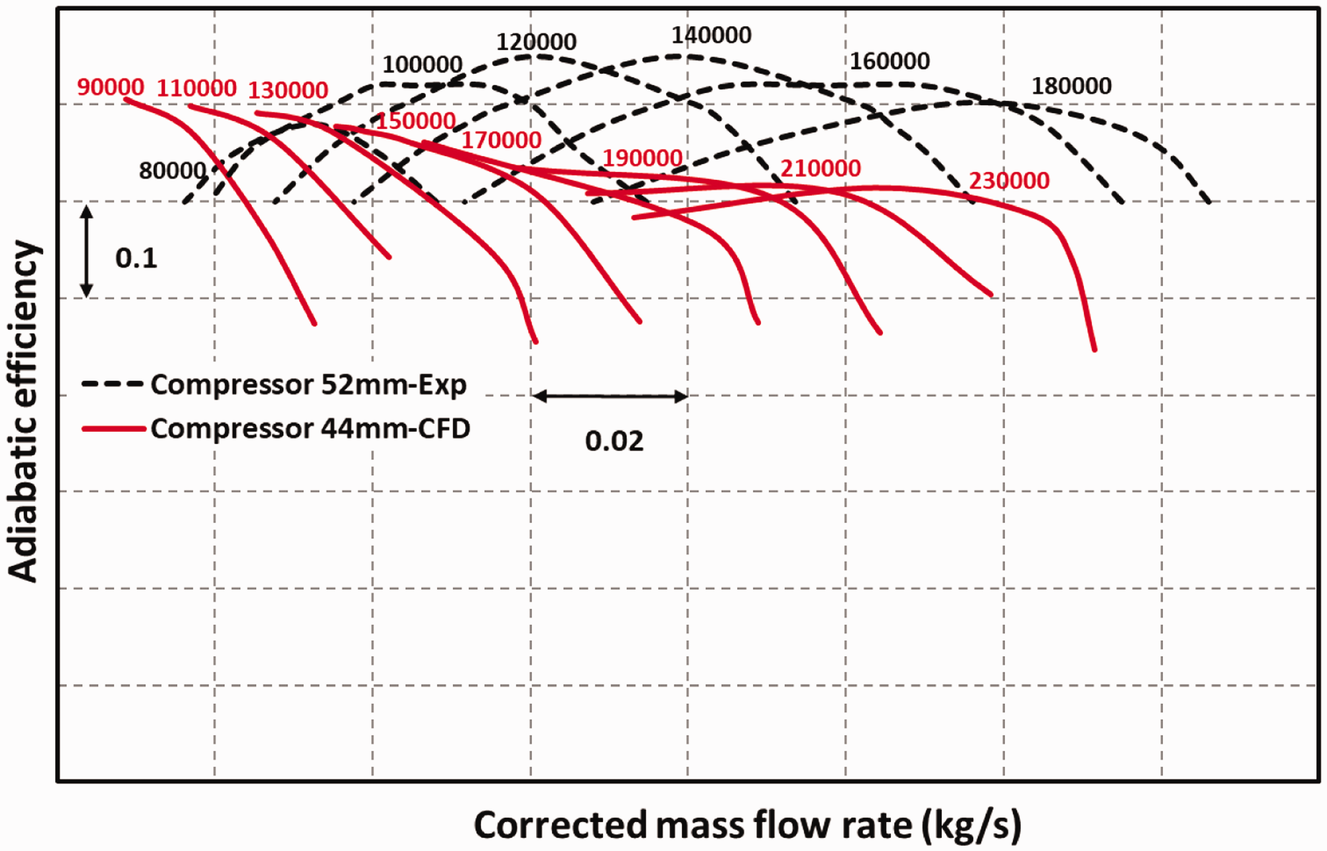
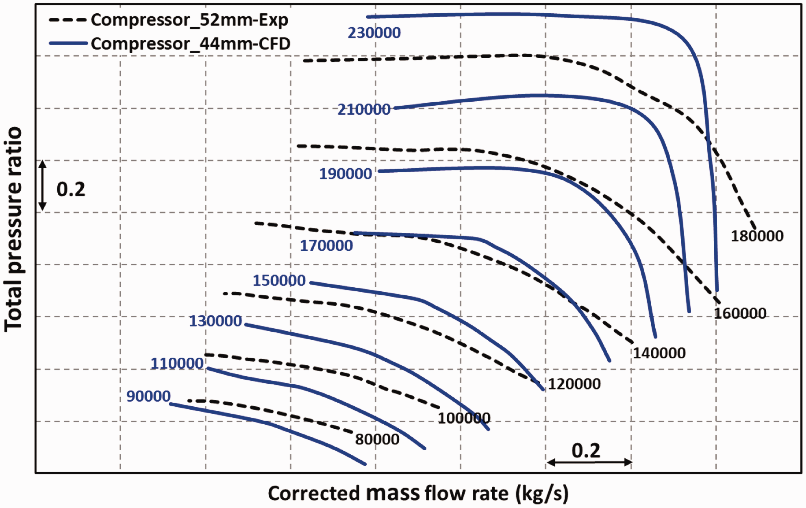
The performance comparison of the 52 mm and 44 mm compressor stage is presented in Figure 11, where a good overlap of the predicted performance of the 44 mm compressor stage on the measured performance of the 52 mm compressor stage is evident. Although experiments in the 44 mm compressor stage are limited to 1,50,000 rpm, the numerical simulations are carried out up to the maximum rotational speed of 2,30,000 rpm to demonstrate the performance capability of the 44 mm compressor stage.
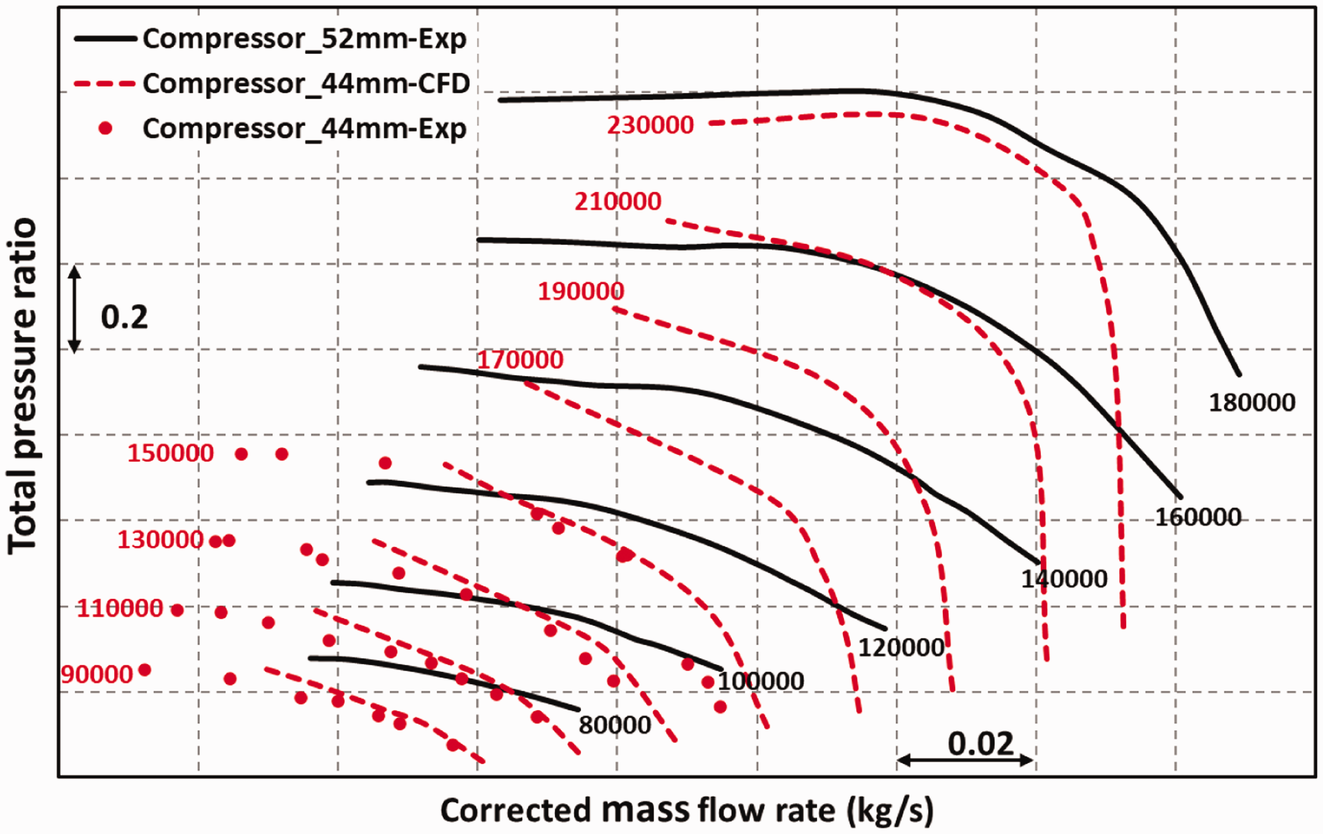
Comparison of the 52 mm and 44 mm compressor stage performance.
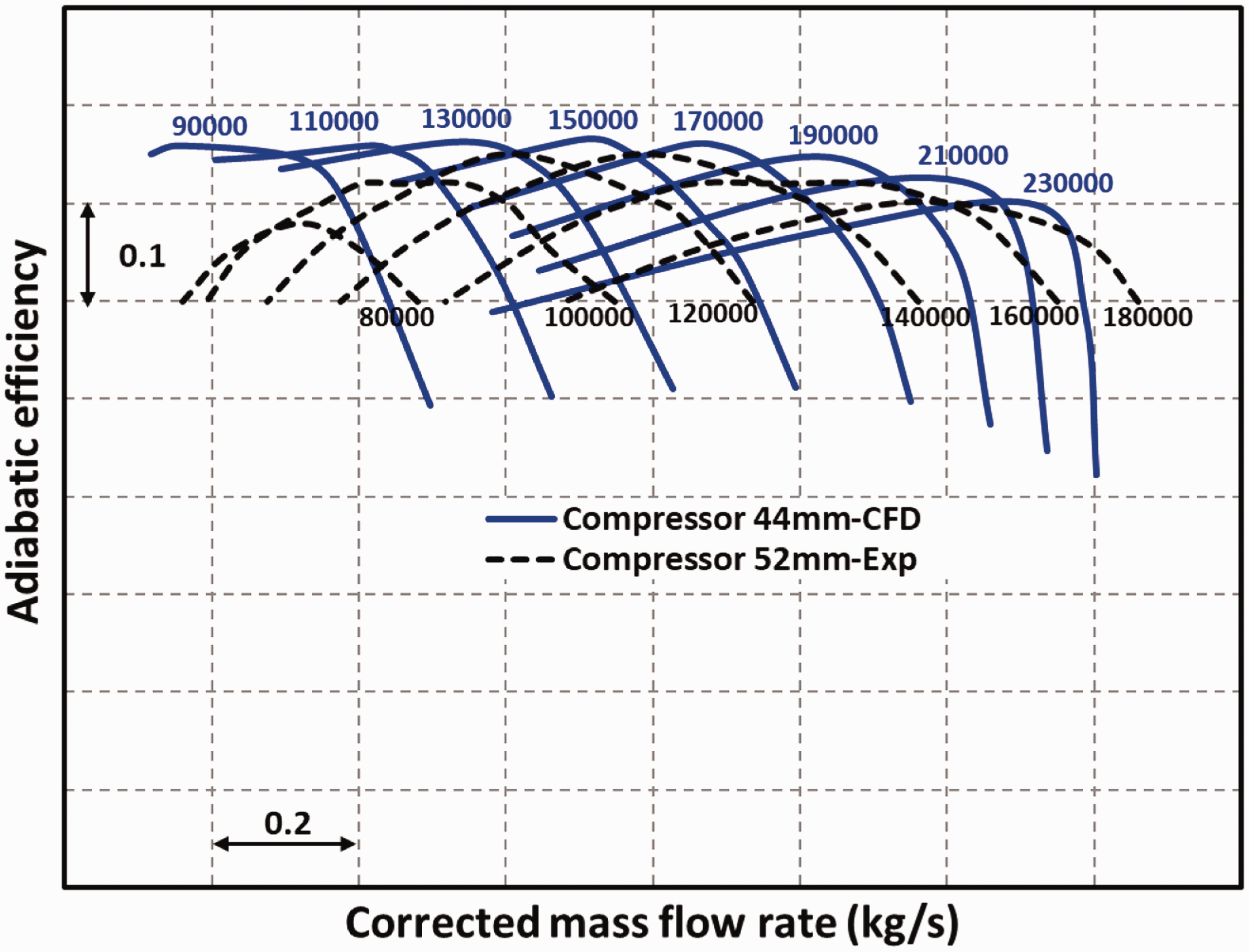
In addition, as shown in Figure 11, the measured and predicted results of the 44 mm compressor stage are in good agreement with around 2% error in performance. Similarly, Figure 12 shows the comparison of the stage efficiencies which are in close agreement with less than 1% difference in efficiencies and highlights the consistency between experiments and numerical analysis. In simulations, the numerical stall or surge point is the last stable point in a given speedline. Beyond this point running the simulation leads to a continuous drop in mass flow rate and pressure ratio followed by the divergence of solution. 46 In experiments, the surge or stall point is detected as the last stable operating point in a given speedline, beyond which the measured mass flow rate and stage outlet pressure fluctuate dramatically.
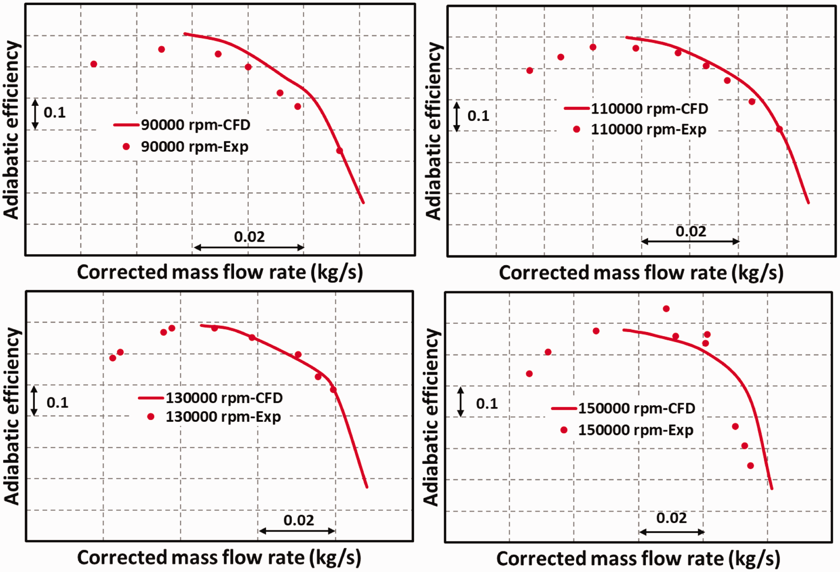
Measured and predicted performance of the 44-mm compressor stage.
It is evident in Figures 11 and 12 that the numerically predicted surge flow rate in the 44 mm compressor stage falls short to reach the surge flow rate measured in the experimental tests. This shortcoming in numerical analysis can be attributed to the numerical instability towards the surge boundary where the compressor stage experiences a highly complex flow, making the numerical solver to diverge. Besides, it has been observed that the numerical simulations are prone to instability when there is a negligible increase in pressure ratio against the larger change in mass flow rate leading to an early compressor stall in numerical simulations. However, based on the experimental performance and its agreement with CFD results up to 1,50,000 rpm, it is likely that experimental results of the 44 mm compressor stage up to 2,30,000 rpm will achieve the surge flow-rate agreeable to the surge flow rate of the 52 mm compressor stage.
The comparison of the 52 mm and 44 mm compressor stage efficiencies are shown in Figure 13. It is apparent from the comparison that the predicted efficiencies in the 44 mm compressor stage are consistently lower than the 52 mm compressor stage measured efficiencies. These lower efficiencies in the 44 mm compressor stage can be attributed to the non-compatible compressor housing to a new 44 mm compressor wheel. As the 44 mm compressor impeller is developed for a larger mass flow rate, the existing diffuser width and volute A/R ratio of 0.33 used in the present tests and simulations appears to be inadequate for this compressor impeller. Here, the volute A/R ratio is a ratio of volute cross-section area to centroid radius. 47
Comparison of the 52 mm and 44 mm compressor stage efficiencies.
Furthermore, Figure 14 shows the contours of the relative Mach number at a pressure ratio of 1.90:1, at a point equally away from the surge and choke boundary at design speed. The meridional and blade-to-blade contour plots indicate high Mach number flow, however, with negligible flow separation at the inducer. The flow separation in the vicinity of the blade shroud is likely due to the interaction between the tip clearance and passage flow. Moreover, as the impeller is designed with the transonic inducer, the Mach number at the blade leading edge varies from subsonic condition to supersonic condition across the blade span. Figure 14(a) shows contours of Mach number at 95% of blade span indicating the maximum Mach number of 1.3 which is inevitable in the transonic impeller. Besides, Figure 14(b) shows the circumferential average Mach number on the meridional plane and X-Y plot demonstrating the subsonic flow at the inducer hub and supersonic flow at the inducer tip.
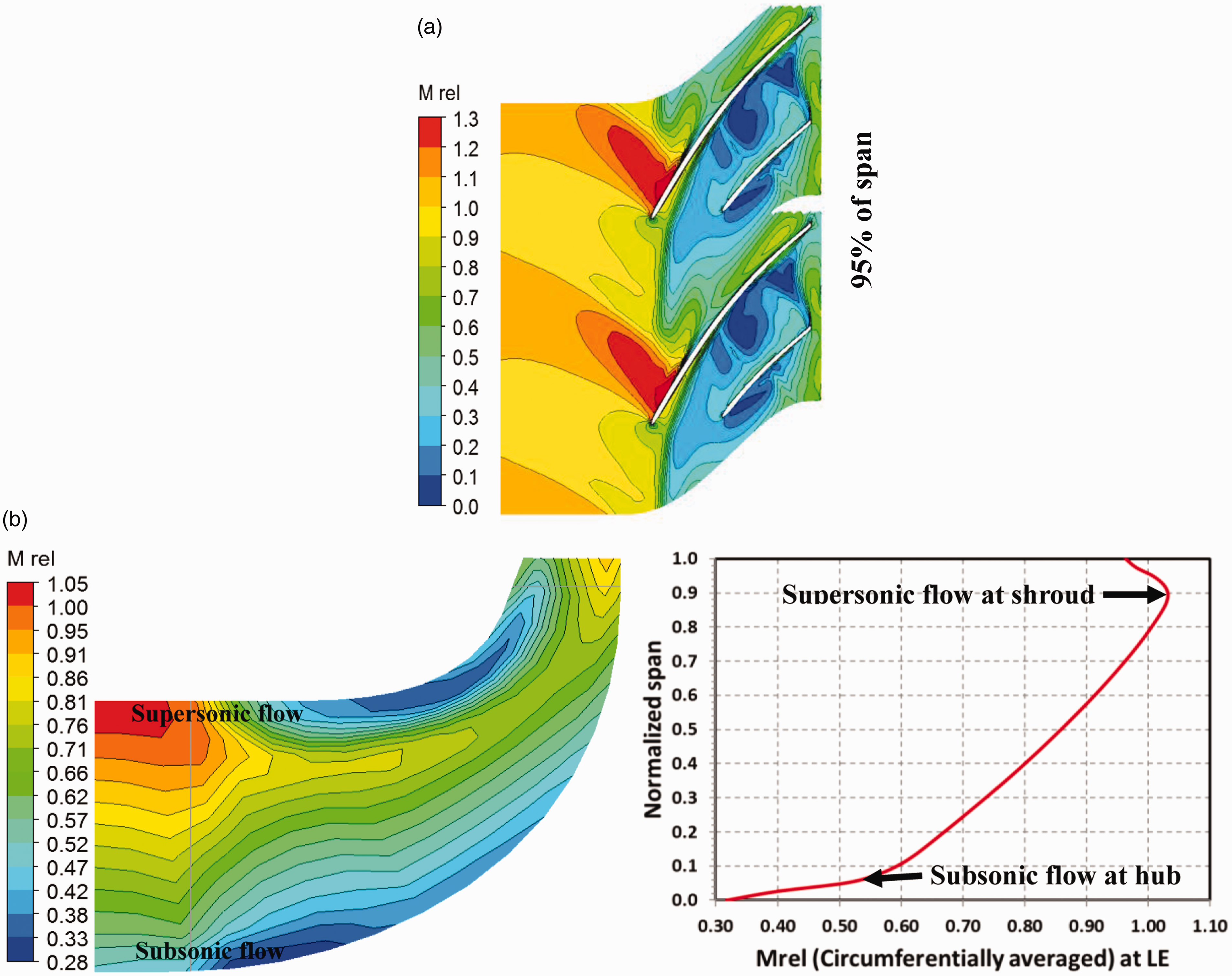
Contours of Mrel (a) on blade-to-blade plane (b) on meridional plane with distribution of Mrel at blade LE.
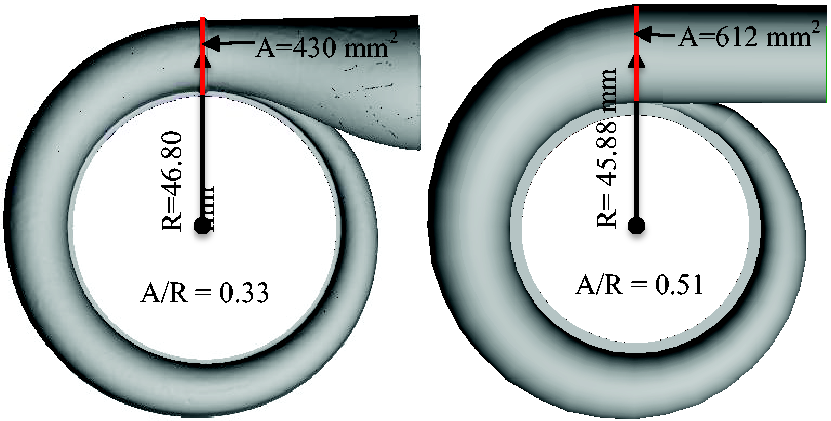
Volute with 0.33 and 0.51 A/R ratio.
In order to overcome the efficiency deficit as demonstrated in Figure 13, a new volute with a 0.51 A/R ratio, equivalent to the A/R ratio of the 52 mm compressor stage is developed and illustrated in Figure 15. This new larger size volute is not only expected to reduce loss in the volute flow path but also likely to facilitate higher mass flow rate compared to the 0.33 A/R ratio volute used in experiments and numerical analysis.
Although a larger volute A/R ratio facilitates more mass flow rate with less friction, a crucial part in improving the 44-compressor stage efficiency is an efficient diffuser. Figure 16 shows the performance of the 44 mm compressor stage with four different diffuser widths varying from 60% to 90% of the blade exducer width. The diffuser outlet to blade outlet ratio of 1.45 is employed in this case against the ratio of 1.60 used in the experiment and numerical analysis. The results show the diffuser width equal to 70% and 80% of the blade exducer width is most promising. However, the diffuser width equal to 70% of the blade exducer width shows relatively better performance even though it predicts marginally higher surge flow rate.
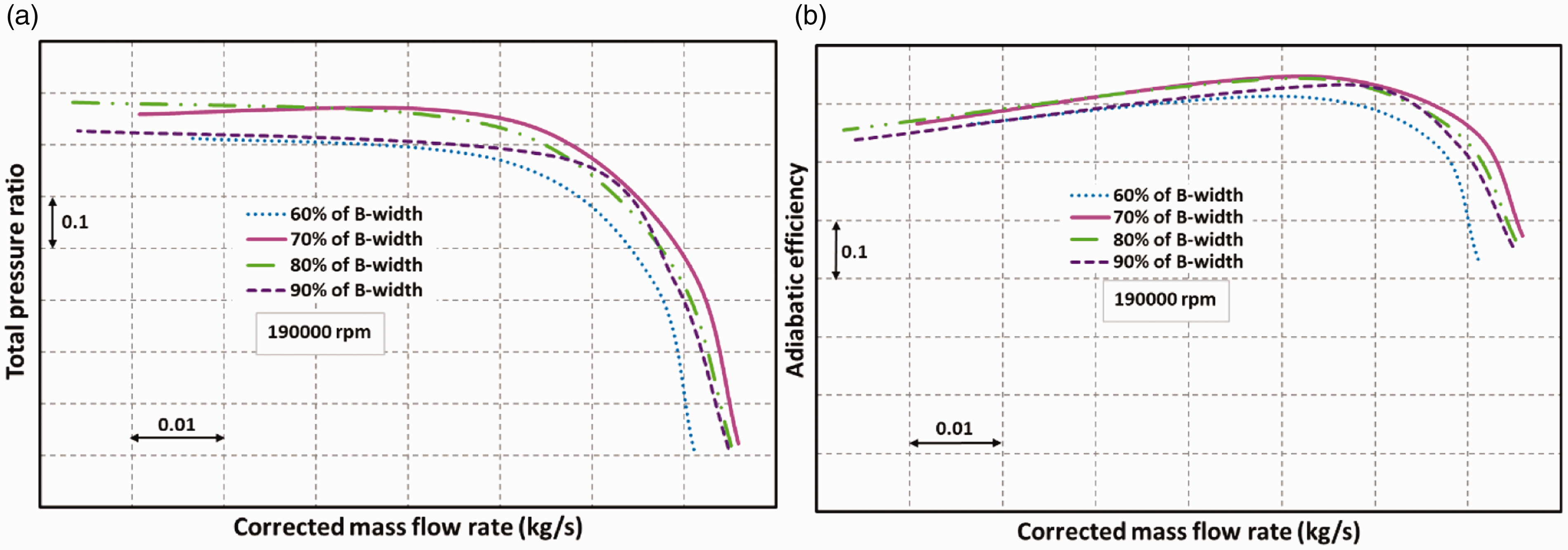
Impact of different diffuser width on the 44 mm compressor stage (a) Total pressure ratio (b) adiabatic efficiency.
The performance map of the 44 mm compressor stage with a 0.51 A/R ratio volute and diffuser width of 2.625 mm, 70% of the blade exducer width is shown in Figures 17 and 18. It is evident from Figure 17 that the predicted performance of the improved 44 mm compressor stage shows comparatively better overlap with the measured performance of the 52 mm compressor stage. However, the predicted performance shows relatively higher surge flow rate, and approximately 6% deficit in choke flow rate at maximum rotational speed due to choking of the blade throat.
Comparison of the 52 mm and improved 44 mm compressor stage performance.
In addition, it is apparent from the improved 44 mm compressor performance map that at higher rotational speeds, the difference in choke flow rate between two consecutive speedlines reduces, exhibiting a narrower gap between choke boundaries. A sudden drop in pressure ratio towards the choke boundaries at higher rotational speeds can be attributed to a higher friction loss in the blade passage. The loss associated with shock waves is also likely to contribute to reducing the pressure ratio. On the other hand, the surge flow rate in the improved 44 mm compressor stage is still predicted to be larger than the 52 mm compressor stage due to numerical instability in CFD simulations. Nonetheless, based on the trend observed in the experimental results for the 44 mm compressor stage in Figures 11 and 12, it is expected that the improved 44 mm compressor stage will achieve the surge flow-rate similar to or lower than the surge flow rate of the 52 mm compressor stage, resulting in a larger map width.
Furthermore, the predicted efficiencies of the improved 44 mm compressor stage are compared with the measured efficiencies of the 52 mm compressor stage, indicating a good agreement as presented in Figure 18. The peak efficiencies predicted in the improved 44 mm compressor stage are in the range of 70% to 76% depending on the rotational speeds, whereas the measured peak efficiencies in the 52 mm compressor stage fall in the range of 68% to 75%. This result comparison demonstrates that the compatibility of the diffuser width, diffuser length, and volute A/R ratio to the impeller is equally important alongside the efficient impeller in order to achieve a better stage efficiencies.
Comparison of the 52 mm and improved 44 mm compressor stage efficiencies.
Conclusions
A small-scale 44 mm diameter compressor is designed with transonic blading to achieve the performance of the 52 mm compressor, a 20% larger diameter compressor. The predicted performance of the 44 mm compressor shows close agreement with the measured performance with around 2% error in performance. Likewise, the comparison between the 52 mm compressor stage and the improved 44 mm compressor stage having the enlarged volute with 0.51 A/R ratio and efficient diffuser width shows a good overlap of the performance. This finding indicates the importance of the compatible diffuser width and volute A/R ratio in the compressor stage. The diffuser width equal to 70% of the blade exducer width appears to be most promising in the compressor stage. Moreover, the blade inducer-to-exducer radius ratio and inlet relative flow angle at the shroud are exhibit to be key parameters that determine the magnitude of the inlet relative Mach number
Footnotes
Declaration of Conflicting Interests
The author(s) declared no potential conflicts of interest with respect to the research, authorship, and/or publication of this article.
Funding
The author(s) disclosed receipt of the following financial support for the research, authorship, and/or publication of this article: The research was jointly supported by the European Horizon 2020 project 644971, 2017 T-TRIG project of the UK Department for Transport, project 104021, and Birmingham High Performance Turbomachinery.