
Abstract
As the demand for the transmission of electric power and communication signals in automotive and aerospace vehicles increases, so does the number of structures comprising simplified one-dimensional attachments, such as electrical cabling, affixed to a host plate like primary structure. These attachments are typically uncertain in their geometric or material properties, potentially affecting the response of the built-up structure. Difficulties then arise in the prediction of the response of the assembly. This study shows how the variability, due to the uncertain attachments, might be reduced by considering flexible connections. A mobility analysis compares systems connected with either rigid links or elastic springs. A frequency is identified at which the assembly dynamically uncouples; the effect on the host response variability due to the uncertain attachment decreases above this frequency with a reduction of the order of 60 dB in the coefficient of variation. This uncoupling or effective isolation frequency can be simply estimated from the mobility of the elastic connection and the properties of the nominal structural attachment. For design purposes, this frequency can be adjusted to achieve a more predictable response above a given frequency.
Introduction
Vibration analysis requires the dynamic characteristics of a structure to be known, so geometry and mechanical properties, boundary conditions and connections between the structural components are necessary input parameters. 1 One issue for estimating the structural response is the manufacturing process variability in the nominal material and geometric properties, leading to different dynamic responses of nominally identical components. 2 This article proposes an approach to reduce the variability in coupled structures comprising a one-dimensional waveguide connected to a two-dimensional waveguide through a finite number of point connections. The one-dimensional waveguide can represent structures such as cable bundles, hydraulic pipes, reinforcement ribs, etc., whilst the host structure can be an aircraft fuselage, a satellite body or a car body-in-white.
Aerospace electrical cable or wiring harnesses are often 10% of the total mass, but they could be as much as 3 30%. The current standard method of modelling these as lumped masses at connection locations is not sufficiently accurate. Therefore, a model is required that goes beyond considering the attachment as lumped masses taking into account the structural dynamic interaction of structures such as electrical wiring, or determining when this interaction is relevant for the forced response. 3 The effects of adding light (harness-to-host mass ratio up to 8%) untensioned cabling to a structure can be divided into two frequency ranges. At low frequencies, due to mass loading, the natural frequencies of the host structure are lowered and the positions of the modelled point masses could be optimised to minimise the response over a frequency band. 4 At high frequencies, wiring cables increase the system modal damping ratios; strongly coupled modes can result in a dramatic reduction in the system quality factors. 5 This damping benefit contrasts to uncertainty due to the variability at higher frequencies being sensitive to relatively small changes in the cables, i.e. cross-section geometry, additional taping or sheathing. 5 Assuming that the source of variability in the response of the connected structure is largely due to uncertainty in the wiring represented as a one-dimensional waveguide, the use of nominally identical elastic connections could be used to reduce this uncertainty and identify an isolation frequency. The uncertainties in the one-dimensional waveguide could be due to variation in the geometry, density, etc. but herein it is considered that the Young’s modulus is uncertain and varies along the length of the wiring represented by a low stiffness beam.
Mobility analysis and formulation
Mobility methods can be used for describing the behaviour of continuous or simple lumped parameter systems 6 and for the dynamic behaviour of both a directly excited structure and one connected to it in a coupled system. 7 For the point connection, it is assumed that coupling is only through the transverse out-of-plane deflections with small displacements in both the host plate and the attached beam, hence linearity is assumed. A typical automotive wiring has a non-negligible bending stiffness, 8 therefore for later beam to plate models it is assumed that the cable is represented by a low stiffness linear beam, with no contact other than at discrete point connections. It is important to note that the shear deformation and rotary inertia of the beam are also neglected in the study.
Wave-based methods such as the wave based method9,10 (WBM), the spectral element method,11,12 the semi-analytical FE method
13
and the wave and finite element14–16 (WFE) usually require the structures to be homogeneous; this article deals with uncertain one-dimensional structural attachments. They are assumed to have slowly varying properties along their length, i.e. there are no sudden changes in the properties along their length. This condition is met if
17
Figure 1 shows the waves necessary to derive the beam mobility. The mobility at an arbitrary point Y(ω) (in ms−1N−1) is given by
Waves required to derive the mobility at an arbitrary point. The superscripts + and − denote waves propagating or decaying from the left to right or right to left, respectively. The subscript denotes the waves at a particular point with N denoting an evanescent or near field decaying wave. Symbol 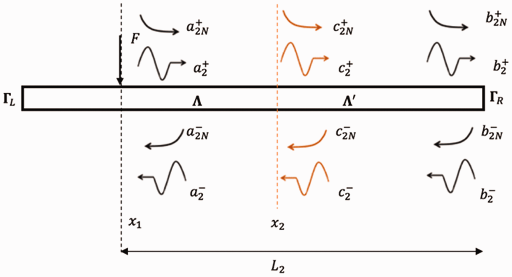

The variability of the mechanical properties can be treated as random fields
21
and can be modelled using spatially correlated variability.22–24 One can describe a random field
The KL expansion is used for the zero-mean random field, truncating the series at

Coupling structures using a mobility approach
Once the input and transfer mobilities are known, it is possible to couple the structures using the continuity and equilibrium conditions expressed in terms of the mobility matrices. Abolfathi et al. 28 used mobilities to connect plates with only one connection point to investigate the connected structure variability. Uncertain parameters for the mount and the plates were considered, considering the properties of the mount and modal damping being more likely to be uncertain than the plate properties. Here the uncertain attachment, cable wiring with slowly varying properties represented by low bending stiffness beams, is connected to a host plate through multiple rigid connection points. Subsequently, identical elastic springs20,29 are used to represent massless elastic mounts. When the elastic spring stiffness is significantly higher than the point dynamic stiffness of the two connected structures, then the relative displacement of the spring ends is negligible and a rigid link assumption is valid. Physically this might occur with stiff metal fastening connections.
For simplicity, an external harmonic point force is applied to the plate at one of the N connections. The number of points of interest on the plate and the beam are set equal to N. If this is not the case, the dimensions of the mobility matrices for the host plate and connected beam are different, with additional points other than the connections considered. The present analysis neglects the offset of the beam neutral axis from the plate, with both the beam and plate vibrating in flexure only.
Infinite structures
Infinite structures are considered, because they can represent the general behaviour of finite structures. At higher frequencies, finite structures tend to the behaviour of an infinite structure. Moreover, the frequency-averaged response of a finite structure tends to that of an infinite structure.7,30
For rigid links, the velocity continuity implies that at the connection points

The separate beam and plate velocities can be calculated using


From the previous set of equations, one can determine the vector for the transmitted forces

Equation (7) can be used in equations (5) and (6) to calculate the forced response of the plate or beam when they are connected due to an external force vector
When using linear elastic translational springs as the connection, at each connection, an internal force is produced by the spring on the beam and plate. These forces, being given by Hooke’s Law at the ends of the spring, are equal in magnitude but opposite in direction. This extension is the difference in the displacements of the beam and plate at the respective points.
Figure 2 shows the forces on a system comprising an infinite plate connected to an infinite beam through a finite number of spring connections. In this diagram the external force is applied at the second of the N connection points, but in principle could be at any alternative location thus requiring suitable equation reformulation.
Infinite beam connected to an infinite plate through an arbitrary finite number N elastic springs. fk are the reaction forces acting on the beam and plate with other reaction forces at the other springs not shown.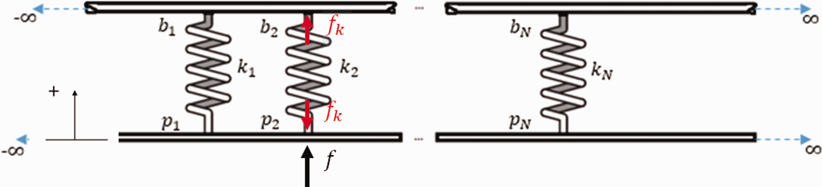
Analogous to the rigid link


Rewriting

By Hooke’s Law, one can evaluate all of the spring forces in terms of the velocities at the spring ends


Nominal properties of the infinite and finite modelled beams, plates and connection stiffnesses.
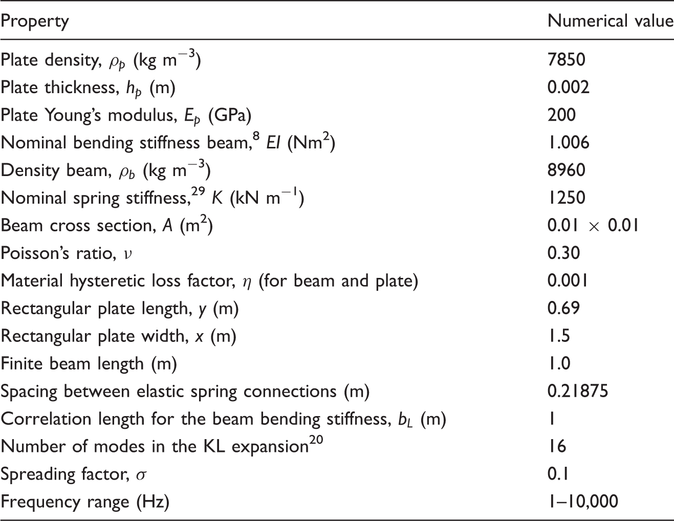
Figure 3 shows the magnitude of the point mobilities for the infinite beam, plate and for an elastic spring. The expressions for those are respectively:
6
The magnitude of the point mobilities for the uncoupled beam and plate and when a single connection is introduced. The frequency where the minimum of the response on the plate occurs is 868 Hz.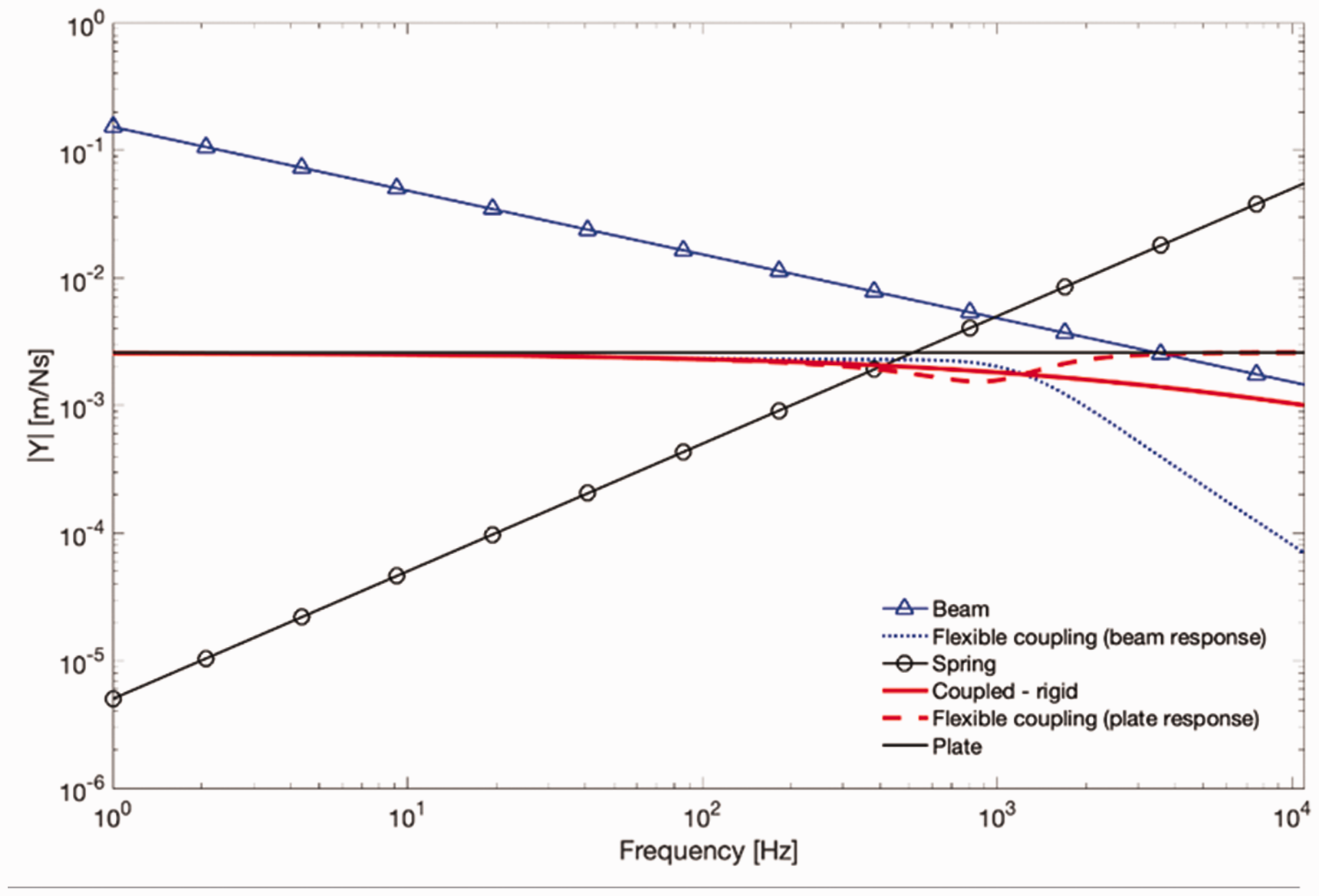
Finite structures – multiple rigid connections
The reflections due to the boundaries of the structures lead to resonances. Here a finite homogenous plate is connected to different simulated beams, which represent cables with the same nominal properties. The beams have a slowly varying Young’s modulus to represent the variability. Table 1 gives the properties used in the finite system numerical calculations. Figure 4 shows schematically the coupled finite system. To avoid any effects related to symmetry, the beam is connected off the symmetry axes of the rectangular plate. For simplicity, an external force is applied at the central connection, point 3, acting on the plate. This is a unit magnitude force with a constant spectrum from 1 Hz to 10 kHz. Equally spaced connections and springs with identical nominal stiffness are considered. Multiple force excitation points could be considered, with the appropriate transformation matrices to map it to the connection points.
Geometry of the coupled system. A 1-m long beam is connected to a rectangular homogeneous plate through five point connections (^). An external transverse force is applied to the plate at the central connection point.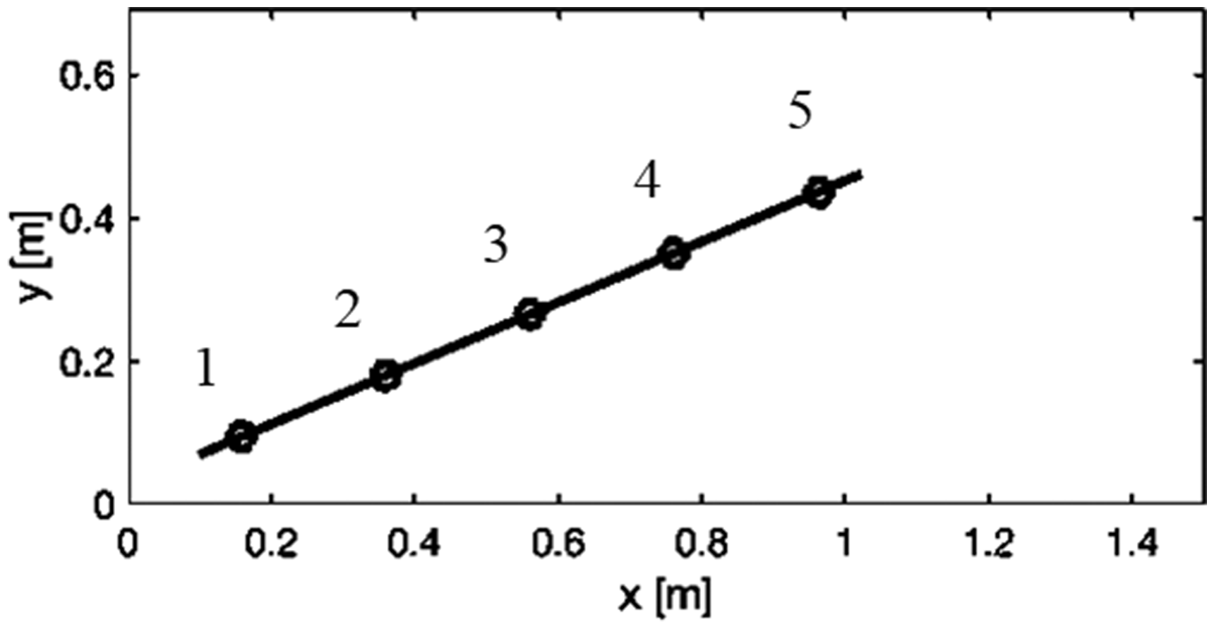
The slowly varying low bending stiffness for the 10 different beams are shown in Figure 5. Figure 6(a) shows the convergence of the KL expansion. The KL expansion has converged
2
when Bending stiffness for the 10 different slowly varying beams compared to the nominal bending stiffness. Convergence of the KL expansion and validity of the field for the WKB approximation for a typical beam sample. (a) shows the relative size of the KL eigenvalues. (b) shows the slowly varying condition
17
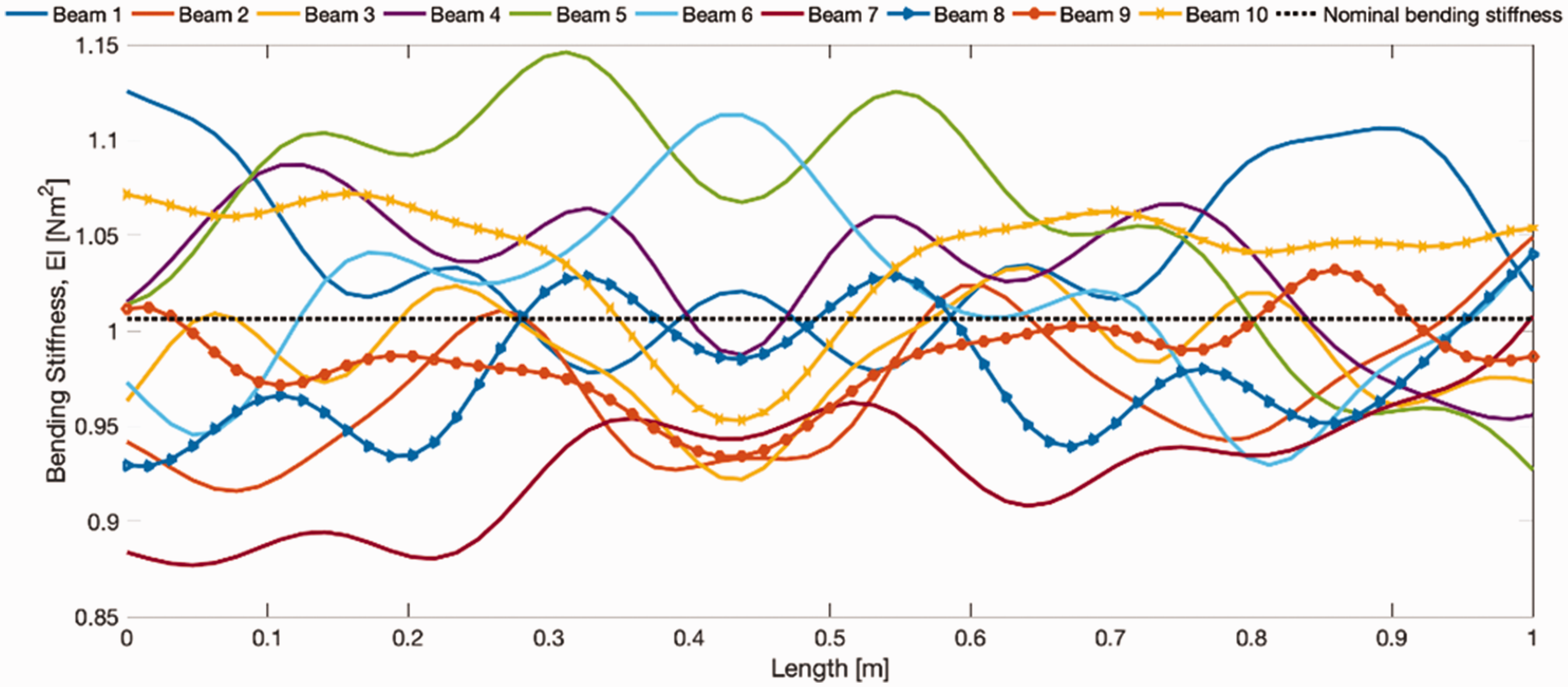
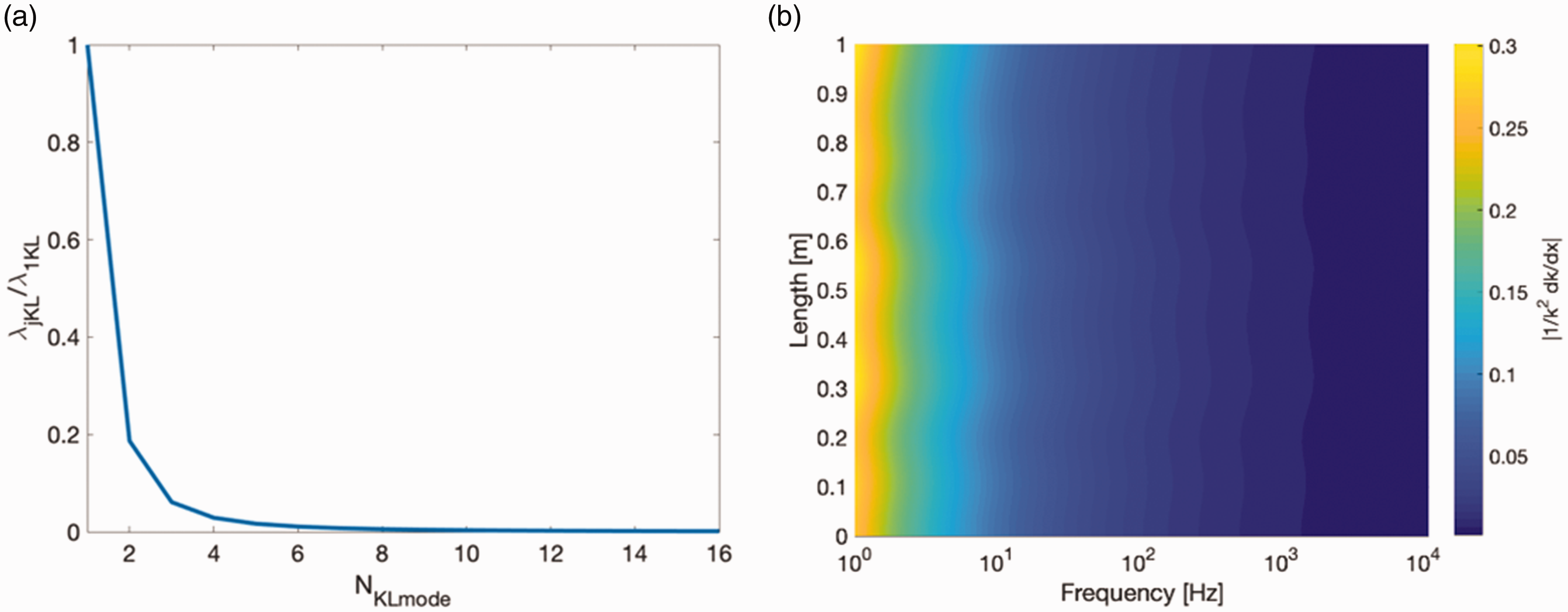
Figure 7(a) shows the point mobility of the nominal beam and plate along with the coupled system comprising a nominal beam connected to a host plate. A slight mass loading effect is seen on the plate at lower frequencies with the corresponding resonance frequencies reduced. Figure 7(b) shows the mobility for the 10 different beams alone.
The point mobilities for the finite systems using rigid links. In (a) the system with nominal properties and in (b) the magnitude for the beam mobilities, considering the 10 different slowly varying cases. The dotted-dashed line is the limits of the region which cover the 95% response bounds and the triangles through the maximum values of the peaks.
30
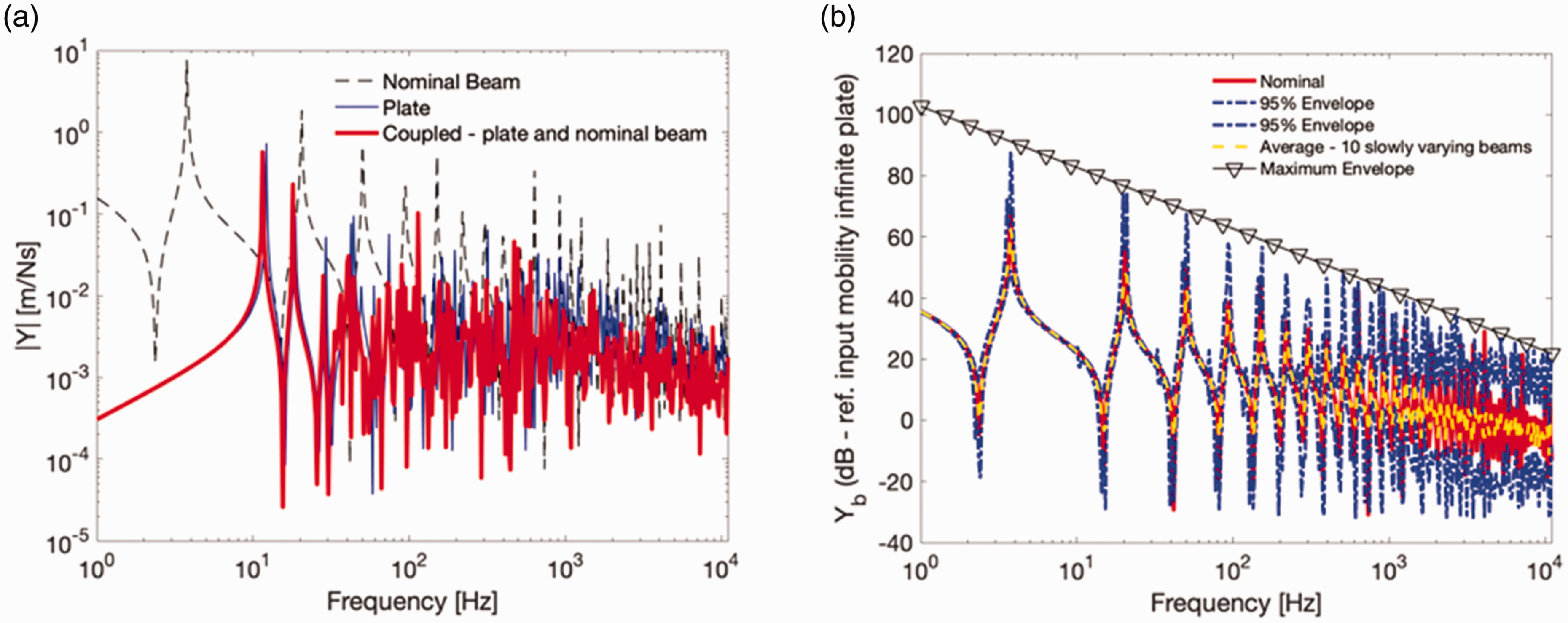
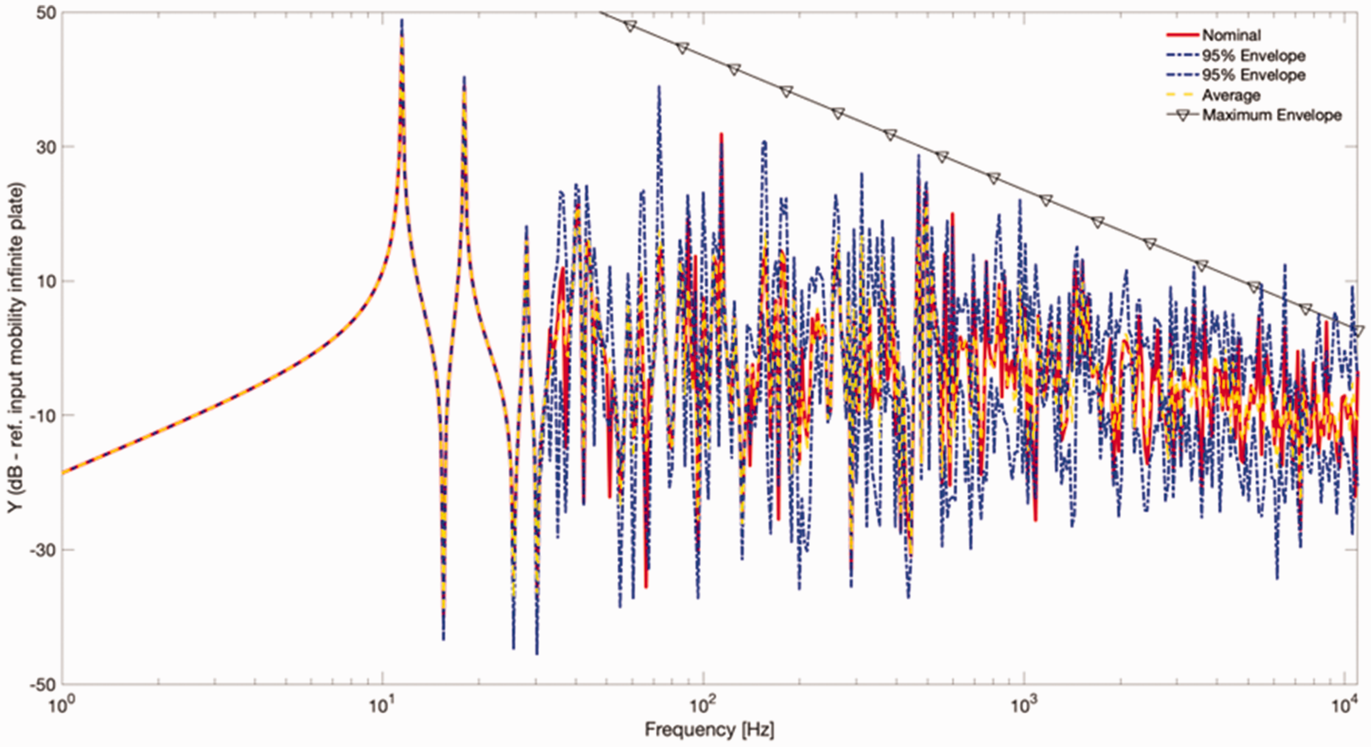
Figure 8 shows the envelope, covering 95% of the range of the point response of the coupled system calculated at the excitation point on the plate when the 10 different beams are separately considered. At lower frequencies the variability due to the uncertain beams do not affect the response of the coupled system, since it is dominated by the less mobile plate element at these frequencies. At higher frequencies, the 95% bounds for the response spreads out around the response of the nominal case, showing that the variability due to the different beams start to affect the response of the built-up structure.
Response of the coupled finite system at the plate considering rigid connections. The 95% envelope is the range of response when the different beams are considered separately and triangles for the theoretical maximum envelope for the peaks of the response of the plate.
30
Finite structures – multiple flexible transverse spring connections
Figure 9 shows that at lower frequencies the uncertain attached structure does not affect the response of the coupled system calculated on the host plate. At higher frequencies, instead of the spread in the response around the response of the nominal system the envelope of the point response converges to the predicted response when the nominal uniform properties are considered. In this case, from the analysis of the infinite structure, the response is actually governed again by the host plate. The response of an equivalent infinite built-up system considering the nominal properties is also shown in order to infer the frequency where the uncoupling occurs.
Response of the coupled finite system using elastic spring connections. The 95% envelope is the range of response when the different beams are considered separately.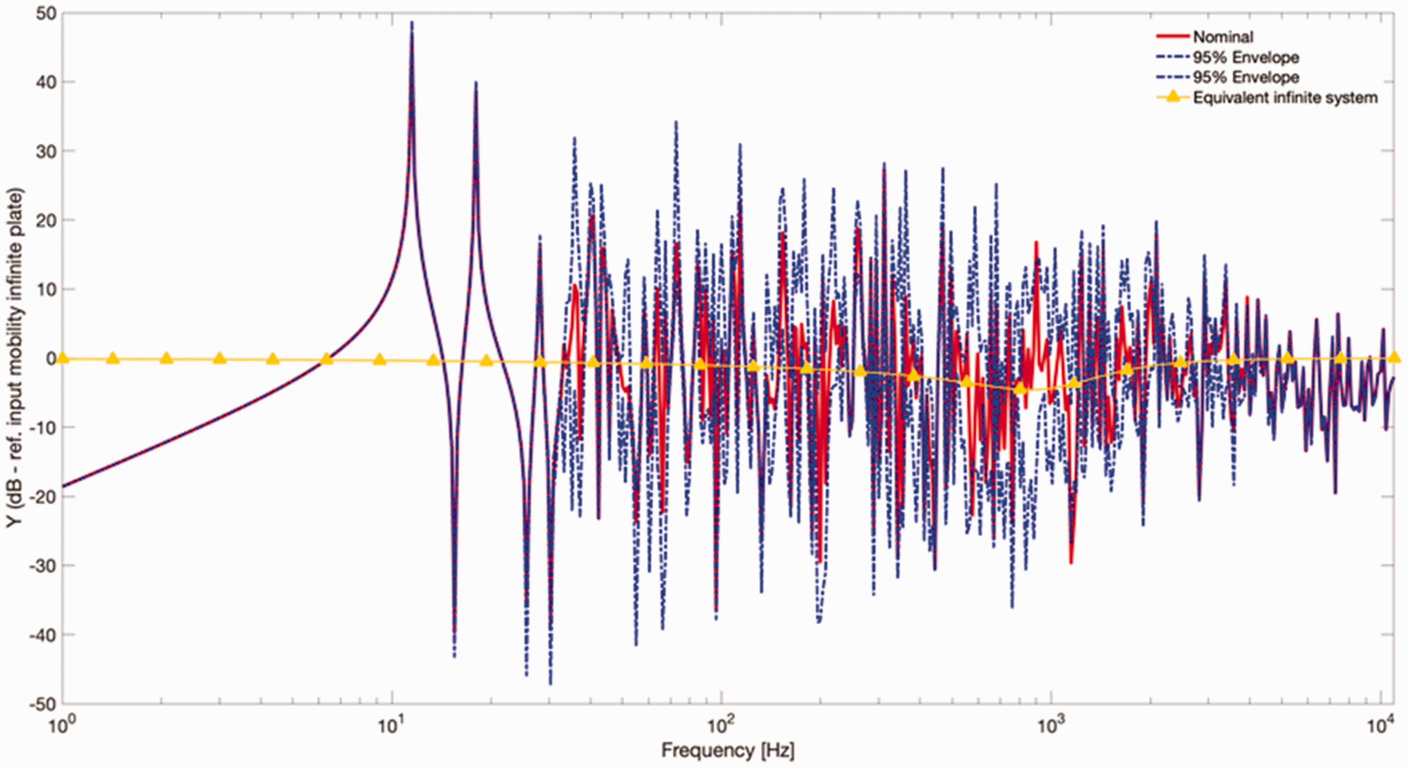
Comparing the previous results, introducing flexible links reduces the variability of the coupled system response. Figure 10 shows a direct comparison of the effects of considering flexibility in the connections. It is possible to see that, in this case, above the first three resonances, where the response was governed by the response of the host plate, the change in the stiffness of the coupled uncertain beam introduces a spread around the response for the nominal case. However, above the uncoupling frequency this spread is reduced. This can be seen by the collapse of the envelope for the response of the uncertain system to that for the response of the nominal uniform coupled system. The coefficient of variation (CoV) is given by the division of the standard deviation of a population by the mean of said population using the response at each frequency. The higher the CoV, the more variability that exists. Below the uncoupling frequency, around 860 Hz, the two CoV values for the rigid and elastic connections have similar behaviour. Above said frequency, the CoV of the elastically coupled system starts to reduce, producing extremely low statistical variation at higher frequencies, i.e. there is no noticeable variability in the coupled response. At these higher frequencies, differences of up to around 60 dB occur comparing the CoV for rigid and flexible links. In comparison with the simple isolation effectiveness of connected systems, typically used for a single point connection and expressed in terms of the response velocity ratio of the secondary system without and with the isolation being present, a similar reduction in the secondary system response (in this case the beam) of 40 dB per decade is observed above the isolation frequency. Therefore, if one needs to reduce the variability of the response above a given frequency of a built-up structure, such as a satellite, due to an uncertain attachment, one can design an appropriate connection, i.e., with a given stiffness, that would uncouple the system in the desired range.
Nondimensional coefficient of variation comparison for the response of the coupled systems with rigid links, flexible connections and for the uncertain beam ensemble. The point mobility is used for (a), Point 3 in Figure 4 and the transfer mobility to the beam for (b); the numbers in the upper left corner of the plots relate to the connection points shown in Figure 4. The vertical solid line marks the frequency for the minimum of the magnitude of the coupled infinite system occurs (868 Hz), whilst the vertical dashed line uses the approximate expression for the uncoupling frequency from the properties of the spring and infinite beam (935 Hz).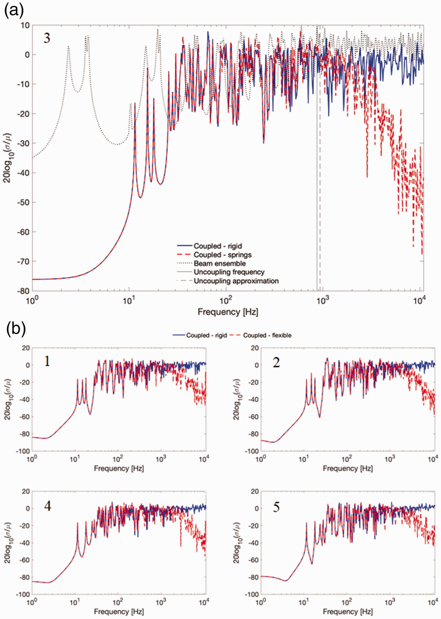
The CoV values for the point mobility of the uncertain beams rigidly connected are also shown in Figure 10(a). They are slightly higher than the CoV values for the rigidly coupled nominal system, except at lower frequencies when the coupled system is governed by the response of the host plate. At these frequencies, there is virtually no variability in the coupled system. Figure 10(b) shows that the same trend is followed at the other connection points and shows that using flexible links is a reliable way of controlling the variability of the host structure response.
Concluding remarks
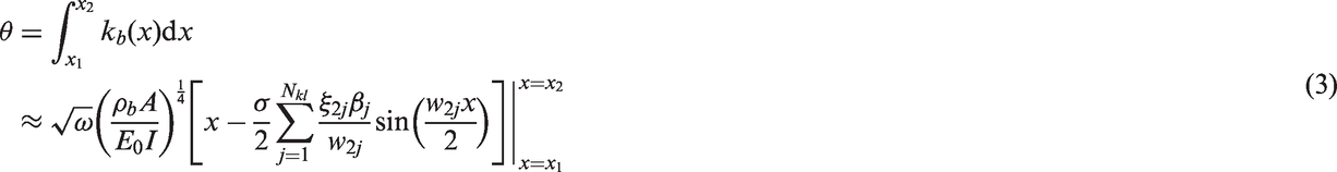
In this work, a potential methodology for controlling the propagation of variability in connected structures comprising of uncertain beam structures connected to a host plate structure was investigated using an equivalent set of simplified models. The uncertain structures, representative of cable bundles, were modelled as beams with slowly varying properties. Different beams were connected to a plate to illustrate the variability in the response of the built-up structure when uncertain structural attachments are considered. The multiple point structural couplings were assembled using a mobility approach. For that, the mobility of a beam with slowly varying properties at any arbitrary point was derived using the WKB approximation.
Rigid links and flexible links in the form of transverse elastic springs were considered. The approach could be extended for other models of connections provided that the mobility matrices for the actual links are known. No variability in the stiffness of the springs, the spacing between the connections or the host structure was considered. At lower frequencies, the connected beam produces a mass load effect on the response of the coupled system. The presence of flexible links results in an uncoupling of the two connected structures above a much higher frequency. This uncoupling frequency can be calculated using the equivalent nominal properties infinite system, which is a system comprising an infinite plate connected to an infinite beam through a single elastic spring.
A comparison between the responses of the coupled system when rigid links were considered versus flexible links is quantified using the coefficient of variation. For frequencies above the uncoupling frequency, the response of the coupled system is governed by the response of the excited host plate and the variability due to the uncertain structure has no effect on the built-up structure when flexible links were considered. A reduction of the order of 60 dB in the CoV can be seen when flexible links are used. In both the point and transfer response this uncoupling phenomenon occurs. This uncoupling frequency could be a target to be optimised or tuned accordingly for vibration control requirements.
Footnotes
Declaration of Conflicting Interests
The author(s) declared no potential conflicts of interest with respect to the research, authorship, and/or publication of this article.
Funding
The author(s) disclosed receipt of the following financial support for the research, authorship, and/or publication of this article: This work was supported by the Brazilian National Council of Research CNPq [process number 231744/2013-7].