
Abstract
The paper describes the latest technological solutions in rolling bearings (ball and roller) used in refrigerant compressors. First, the numerous tribological challenges faced by rolling contacts in a lubricant environment made of oil and refrigerant mixture are discussed. It is followed by a description of the even tougher conditions derived by the replacement of the more chemically stable pre-Montreal and pre-Kyoto Protocol refrigerants by the new generation of more environmental friendly refrigerants. In these conditions, rolling bearings are expected to suffer from surface distress and sometimes corrosion fatigue. Thus, attempts to model these conditions by using advanced tribological models are described. Finally, descriptions of different solutions in rolling bearings in refrigerant compressors facing challenges in lubrication and bearing life are described, all the way from traditional oil–refrigerant mixture lubrication up to the latest innovation related to oil-free lubrication, namely the pure refrigerant lubrication.
Introduction
Since the early 1990s, researchers have been developing technologies for rolling bearings in refrigerant compressors.1,2 In this application, rolling bearings generally are lubricated with a mixture of oil and refrigerant. The latest ones are not considered to be good lubricants for being very thin liquids, where its dilution reduces the viscosity of the mixture, thus increasing the compressibility and reducing the increase of viscosity with pressure (piezo-viscosity), as compared with pure oils. At the time, considerable effort has been invested by researchers in the study of elastohydrodynamic lubrication (EHL) in oil–refrigerant mixtures.3–12 Also, considerable amount of experimental work has been carried out1,2,6,13 to understand the effects of refrigerant dilution in lubricating oils and its consequences on bearing performance and life. It was found that conventional all-steel bearings started to exhibit signs of inadequate lubrication at refrigerant dilution levels of 20% to 30%.2,6
In general, the main problems that rolling bearings are facing in refrigerant compressors are the effects from poor lubrication and high particle contamination (i.e. surface life). Subsurface fatigue is very rare because the loads are moderate. Thus, for poor lubrication or high contamination conditions more robust solutions can be found in conventional rolling bearings with the help of one or more ceramic (Si3N4) rolling elements 13 and/or the use of special surface steel heat treatments (e.g. nitriding and carbonitriding) 14 and some coatings (black oxidizing and others). Even before the Montreal and Kyoto protocols15,16 refrigerants imposed harsh operating conditions (lower lubricant viscosities and piezo-viscosities and higher surface corrosion potential) to rolling bearings. This led, in the past, to the research of alternative bearing designs and materials to improve the bearing operation and life under these poor-lubrication conditions. Studies showed that it was difficult to find a limiting dilution ratio for hybrid bearings, having steel rings and ceramic balls made of silicon nitride (Si3N4). 17 Finally, in 1996, hybrid bearings were run in pure refrigerant with no traces of oil, and the bearings after the feasibility test were in as-new condition. This was a critical test result, which opened up the possibility to use pure refrigerant as a lubricant for special rolling bearings (PRL technology). Since then, research and application development have continued and lead to several additional product features enabling reliable long-term operation,17–20 currently in industrial use.
The current paper summarizes the tribological challenges faced by rolling bearings in refrigerant compressors. It provides an account of modeling and experimental aspects, which prompt explanations for proven technological solutions making rolling bearings one of the most critical machine elements in the positive evolution of the refrigerant compressor technology. It will be impossible to have a complete review of the topic, since there is a very large and diverse literature database in the area of refrigerant compressors. However, the current paper will focus on the tribological aspects of rolling bearings in these conditions. The desired objective is twofold, to show the reader (i) brief application aspects of rolling bearings in these conditions, like different bearing arrangements and potential rolling bearing technologies for this application, (ii) more extensive scientific aspects on lubricant properties of oil–refrigerant mixtures and pure refrigerants and modeling aspects of surface life in rolling bearings. The described double objective is difficult to find in the existing publications.
Description of compressor designs
There are two types of refrigerant compressors where rolling bearings play an important role for compressor function, reliability, and efficiency. These are both industrial size compressors with a motor power range typically in excess of 50 kW.
The first type is the screw compressor (Figure 1(a)). The function of bearings in twin-screw compressors is to provide accurate radial and axial positioning of the rotors and to support rotor load. These functions are to be performed reliably, with low friction and low noise generation. With accurate positioning of the rotors, it is possible to design the compressor with small clearances for high efficiency. Radial positioning accuracy of the rotors is accomplished by using bearings with small operating clearances and high running accuracy (low run-out). Axial positioning accuracy is accomplished by small axial bearing clearance or preload.
Refrigerant compressor types: (a) semi-hermetic screw compressor; (b) centrifugal compressor.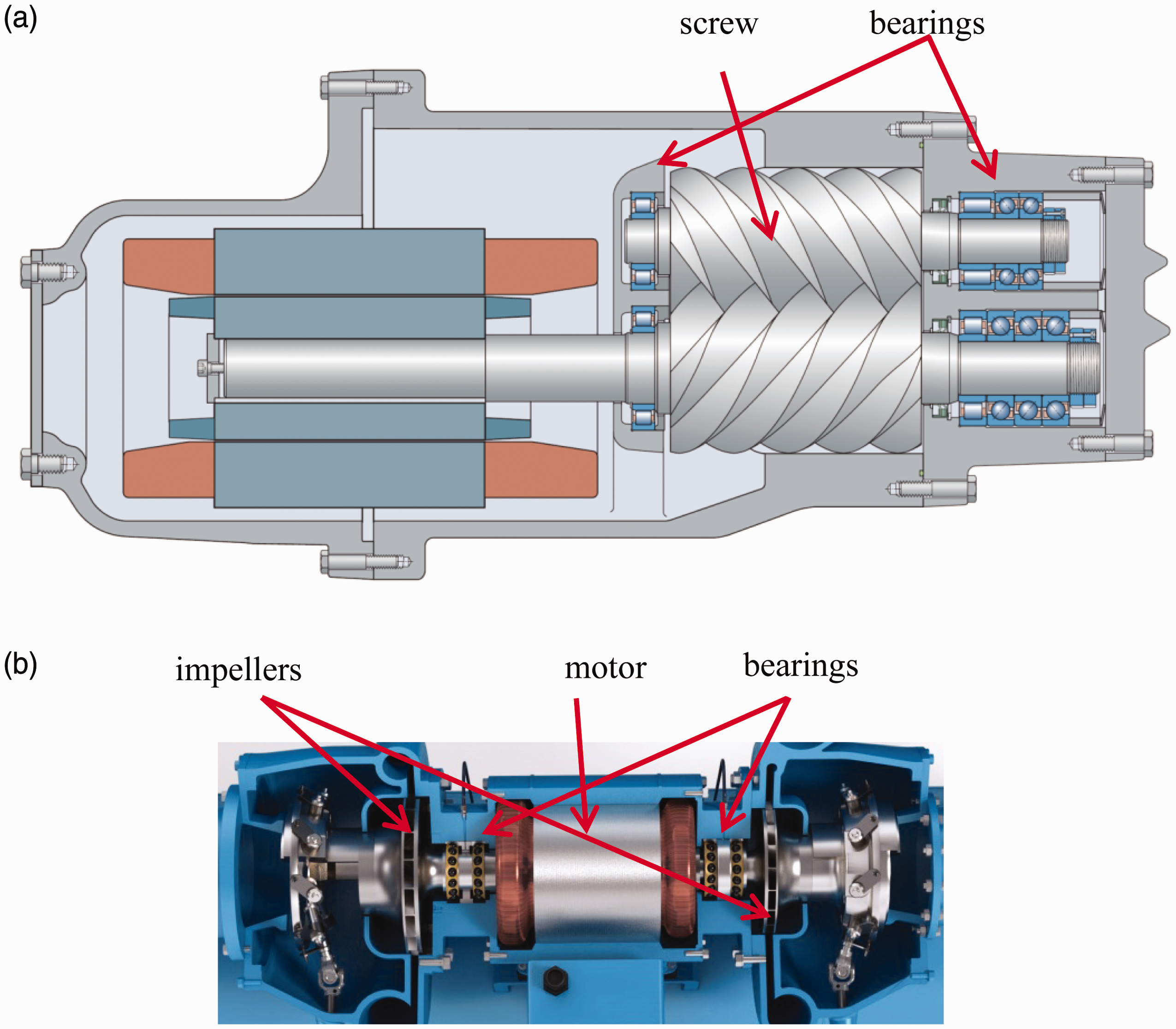
The rotors can be supported on rolling bearings or on a combination of hydrodynamic and rolling bearings. The main advantage with rolling bearings is their small operating clearances. Rolling bearings also have lower friction than hydrodynamic bearings, require less oil for lubrication and cooling, and are less sensitive to momentary loss of lubricant and refrigerant flooding than hydrodynamic bearings. It is important that the rolling elements are separated from bearing rings by a lubricant film. If there is partial contact, then the surfaces must have high resistance to surface distress, in order to maintain bearing function over time.
The second type is the centrifugal compressor (Figure 1(b)). This compressor type is used in higher power ranges than screw compressors. The compression is accomplished by adding kinetic energy to the refrigerant in an impeller. The impeller shaft is either direct coupled to the drive motor or driven through gears. The bearings have traditionally been hydrodynamic bearings, but a relatively recent development is to apply rolling bearings because of lower friction and improved impeller positioning accuracy. The newest technology is to use rolling bearing lubricated by the refrigerant itself, without the addition of oil.
Description of bearing types and arrangements
In screw compressors, the bearing loads are produced by gas pressure on the rotors, gear forces from input and timing gears, rotor forces from transmission of torque from one rotor to the other, and induced loads from the inertia of the rotors at startup. The loads in refrigerant screw compressors can be very high and the bearing size is limited by the space available between the two rotors, this makes the selection of bearings and bearing arrangement critical.
By using a combination of cylindrical roller and angular contact ball bearings, the loads can be separated such that the radial loads are taken by the cylindrical roller bearing and the axial loads by the angular contact ball bearing. The load sharing is accomplished by a radial gap between the outer ring of the angular contact ball bearing and the housing. This way it is not possible for the angular contact ball bearing to take radial load and the cylindrical roller bearing cannot take axial load since it is axially compliant.
There are several advantages with this arrangement. The angular contact ball bearing operates with axial load only and all balls have the same contact loads and contact angles. In this way, cage forces are minimized and load capacity is maximized. With the separation of axial and radial loads into two bearings, the load capacity of the arrangement is optimized. With the angular contact ball bearing mounted with a light fit, it is easy to set the axial position of the rotor and the rotor end clearance. There are many ways to do this. It is also easy to dismount the angular contact ball bearing in case the rotor end clearance needs to be adjusted. A typical bearing arrangement is shown in Figure 2(a).
(a) Typical bearing arrangement for compressors; (b) two-stage compressor with back-to-back impellers positioned at opposite ends of the motor containing a bearing arrangement of two back-to-back pairs of high-speed angular contact ball bearings.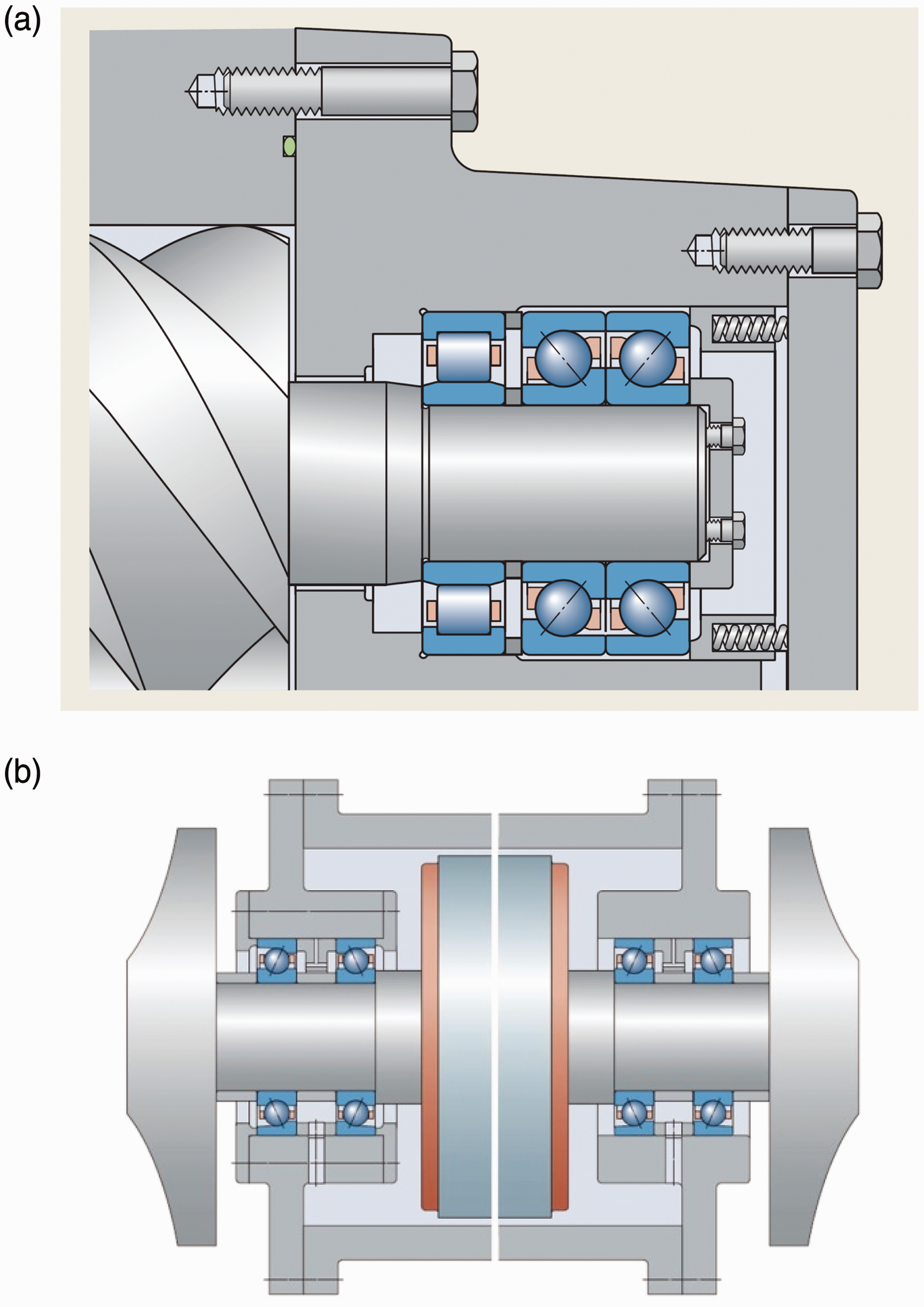
In centrifugal compressors, the loads are primarily produced from pressure on the impeller and in gear-driven designs, from gear forces. Rotor weights contribute to radial bearing forces. The impeller shaft speeds are typically higher than speeds in screw compressors. The speed of compressors using low-pressure refrigerants is lower than designs using medium-pressure refrigerants. The driveline and the impeller arrangement play a significant role in bearing selection and arrangement.
In direct drive designs with two impellers back to back, the axial pressure forces from the impellers are balanced and the bearings only see the difference between the two. The radial forces are from the impeller shaft and motor rotor weights and magnetic forces on the motor rotor. The speed is typically high and the net forces are moderate. The preferred bearing arrangement is two back to back pairs of high speed angular contact ball bearings (see Figure 2(b)). In direct drive designs with one or two impellers on one side (see Figure 3(a)), the axial loads can be balanced with balance pistons. The radial loads are uneven, with the heavier load at the impeller end. The bearing set at this end is the locating set, which defines the axial rotor position.
(a) A two-stage compressor with impeller positioned at one side of the extended motor shaft. The bearing arrangement made of two back-to-back pairs of high-speed angular contact ball bearings; (b) high-speed shaft, gear drive, tandem thrust bearings.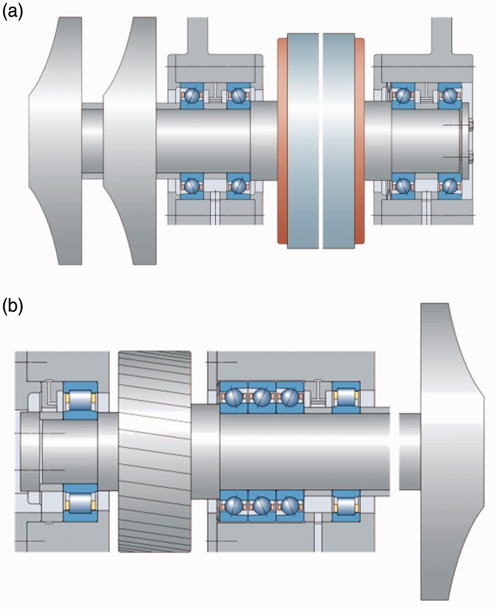
In gear drive designs there are two shafts, one low-speed motor shaft and one high-speed impeller shaft. In the low-speed motor shaft the gear is positioned at one end. There are axial and radial forces from the gear and an additional radial force from the motor weight. The forces on the high-speed impeller shaft can be significant, produced by the gears and pressures on the impeller. A combination of cylindrical roller and angular contact ball bearings is preferred in the arrangement (see Figure 3(b)).
Description of oils and refrigerants
As refrigeration and later air conditioning were being used in the early to mid-1900s, there were many accidents with the refrigerants, such as ammonia and chloromethane, which are both toxic and flammable. When DuPont developed industrially made refrigerants branded Freon such accidents were eliminated, as the new refrigerants were much safer. The commonly used refrigerants for compressors were the low-pressure refrigerant trichlorofluoromethane also known as CFC-11 and medium pressure refrigerants dichlorodifluoromethane also known as CFC-12 and chlorodifluoromethane also known as HCFC-22. The reader should notice that another use of refrigerants is in foam blowing.
In the 1980s, researchers found that a hole in the earth's ozone layer was developing and the ozone depletion potential (ODP) of refrigerants started to be measured. In 1989, a global ban of ozone-depleting refrigerants was agreed upon in the Montreal Protocol. 15 New HCFC and HFC refrigerants were developed having low or no ODP. Low-pressure refrigerant HCFC-123 replaced CFC-11 and medium-pressure refrigerant HFC-134a became a substitute for CFC-12 and CFC-22.
As global warming started to be a concern in the 1990s, another unintended characteristic of refrigerants got more attention—their high global warming potential (GWP). For example, HFC-134a has a GWP of 1300 times that of CO2. At a conference in Kyoto in 1997, an agreement on reduction of global greenhouse gases was proposed, the Kyoto Protocol. 16 The Kyoto Protocol was not ratified by major countries and never fully implemented. At a conference in Kigali, Rwanda in 2016, it was decided to use the more successful format of the Montreal Protocol to control phase down of HFCs. This is referred to as the Kigali Amendment of the Montreal Protocol.
The newer refrigerants were not necessarily simple substitutes for CFCs. HFC-134a refrigerant, for example, is incompatible with the natural mineral oils that were normally used with CFCs. An important property of any refrigerant and oil combination is the ability to dissolve with one another. HFC-134a does not dissolve in mineral oils because of differences in molecular polarity. Polyol ester (POE) or polyalkene glycol (PAG) synthetic lubricants are necessary with this particular refrigerant. Refrigerant HFC-134a is currently used in screw compressors and centrifugal compressors of high speeds. This is one of the so-called medium pressure refrigerants, whose phase down is governed by the Kigali Amendment. The refrigerant HCFC-123 is a low-pressure refrigerant and it is still used mainly in centrifugal compressors. It is being phased out in accordance with the Montreal Protocol.
Later generation refrigerants for compressors
New refrigerants with low GWP and zero ODP are now being developed and phased in by the global refrigeration and air-conditioning industries. The most promising new refrigerants are low-pressure refrigerant HCFO-1233zd and medium-pressure refrigerants HFO-1234ze and HFO-1234yf and various blends containing these refrigerants. The GWP of the new refrigerants is less than five and the ODP is zero. Natural refrigerants such as ammonia and CO2 are also used increasingly but have limitations with toxicity, flammability, and high pressure.
The new refrigerants have a very short atmospheric lifetime, thus they are chemically very active, which can bring corrosion or material incompatibility with the rolling bearings, adding an extra element in the equation. Besides all this, the thermodynamics of the new refrigerants make the oil–refrigerant mixtures more prone to having high concentrations of refrigerants (30% or higher) during important times of the operation cycle.
Lubrication with refrigerants
In all refrigerant compressors (except with magnetic bearings) the refrigerant is part of the lubrication of the bearings; it can be as a oil–refrigerant mixture or as pure refrigerant lubrication (PRL). In any case, the knowledge of the lubricating properties of the refrigerants is needed. Lubrication and tribological aspects are, of course, an important element in the estimation of the bearing life.
Refrigerant lubricating properties
Any EHL film thickness calculation formula or procedure requires of the following lubricant properties: (i) dynamic viscosity,
Summary of approximated film thickness properties for refrigerants as found in the literature.
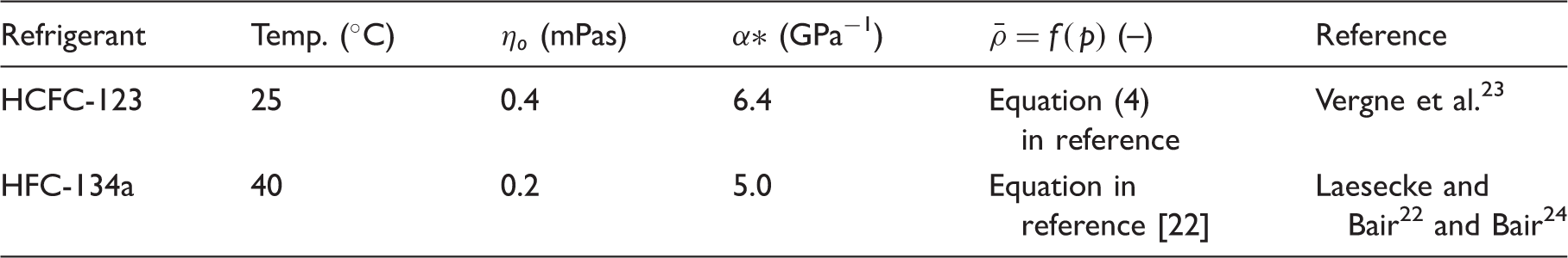
For comparison consider typical oil values of
Friction properties are difficult to measure in pure refrigerants and there is no extensive literature on the subject. However, in Morales-Espejel et al.
19
boundary friction coefficients of
Oil–refrigerant mixtures
Many studies have been carried out in the past to measure or to estimate the film thickness in EHL contacts lubricated with oil–refrigerant mixtures.3–5,7–12 More recent studies of oil–refrigerant mixtures in EHL are in Bair et al.24,25 and Tuomas.
26
In the calculation of film thickness in EHL contacts lubricated with oil–refrigerant mixtures the estimation of the mixture properties is a key intermediate step. Diverse equations have been suggested to estimate viscosity and piezo-viscosity of oil–refrigerant mixtures. For example, Akei and Mizuhara
9
uses the Eyring theory to derive equations for the piezo-viscosity coefficient and viscosity
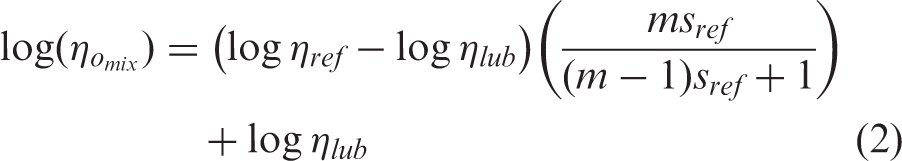
Variation of (a) viscosity and (b) piezo-viscosity coefficient in a mixture of oil and refrigerant as a function of the refrigerant dilution and the molecular weight ratio (m) between the oil and the refrigerant, following equations (1) and (2).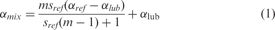
Now, in rolling bearings the lubrication quality parameter (κ) is used as a measure of the lubrication condition in the bearing. This parameter is defined as the ratio between the actual viscosity used in the bearing at the working temperature and the required viscosity recommended by the manufacturer and it is properly defined and explained in ISO 281:2007. The required viscosity is a parameter given by the bearing manufacturer and will not be changed at this point (next, when bearing life is discussed, this assumption can be relaxed). Thus the only parameter that remains to be estimated for a proper calculation of κ in oil–refrigerant mixture conditions is the actual viscosity of the lubricant. Thus, equation (2) can be used for this purpose.
For bearing life calculations, Meyers
2
recommends to increase the required kinematic viscosity of the bearing (
Pure refrigerant lubrication
For centrifugal compressors, the newest trend is to remove oil completely from the lubrication system, either by using magnetic bearings or special hybrid bearings lubricated with refrigerant, this latest one is the so-called pure refrigerant lubrication or PRL technology. For screw compressors the oil will still be required to lubricate the screws. In PRL, the rolling bearings are lubricated only with the refrigerant,17–20 so there is no oil or its contents is so low that it does not account in the lubricant film building-up properties of the refrigerant (e.g. contaminant). For rolling bearings (ball and roller) to work in these conditions, special materials and design are required; a full description of these is given in Morales-Espejel et al. 20 In summary, the main required features are:
PRL hybrid ball and roller bearings are made of:
The highest quality bearing grade silicon nitride (Si3N4) rolling elements with the most stringent defect inspection procedure. Cage with a strong design shape and fiber-reinforced PEEK material. Rings made of stainless high nitrogen through-hardened steel with chemical composition as described in Ragen et al.,
27
heat treated according to in-house specifications and ground to super finished raceways in processes developed in-house.
Apart from this, in the bearings the refrigerant flow has to be directed in a particular way with thermodynamic conditions that ensures refrigerant liquid at all times with sufficient amount.
The work described in Morales-Espejel et al.19,20 shows that with the use of the refrigerant viscosity and piezo-viscosity values, the film thickness can be approximated with the use of the well-known Hamrock and Dowson film thickness equation, 28 at least for the following low-pressure refrigerants: HFO-1233zd and HCFC-123. Laesecke and Bair 22 gave recommendations for film thickness estimations with the medium-pressure refrigerant HFC-134a. Other refrigerants need to be characterized.
Rolling bearing surface distress
The typical limitation in refrigerant compressor bearings, where usual maximum Hertzian pressures are below 2 GPa, is rather surface-related problems, like poor lubrication and contamination, which can bring wear and/or surface distress (known as well as micropitting). Other surface failure modes are also possible e.g. smearing (or adhesive wear); however, it is limited in these applications since in general no large accelerations are experienced. Thus, most of the effort invested to increase the life of the bearings goes to preventing or delaying surface distress from poor lubrication conditions. This is why the authors have included a special section regarding this topic in this paper. The authors also included a modeling example for indications of surface distress occurrence and ways of mitigation. Surface distress is thus strongly influenced by high dilution rates of refrigerant, low viscosities in the mixture, low piezo-viscosity, and high compressibility of the refrigerants, plus sometimes some corrosion due to the chemical activity of the refrigerants or the combination with moisture. In Morales-Espejel et al.,29,30 a bearing life model that separates the surface from the subsurface is described, and this model should in the future much better handle life calculations in these type of applications.
Surface distress phenomenon
Micropitting is a term widely used by the gear industry to describe microsurface spalls and cracks, which sometimes appear on the surface of rolling–sliding contacts. ISO 15243
31
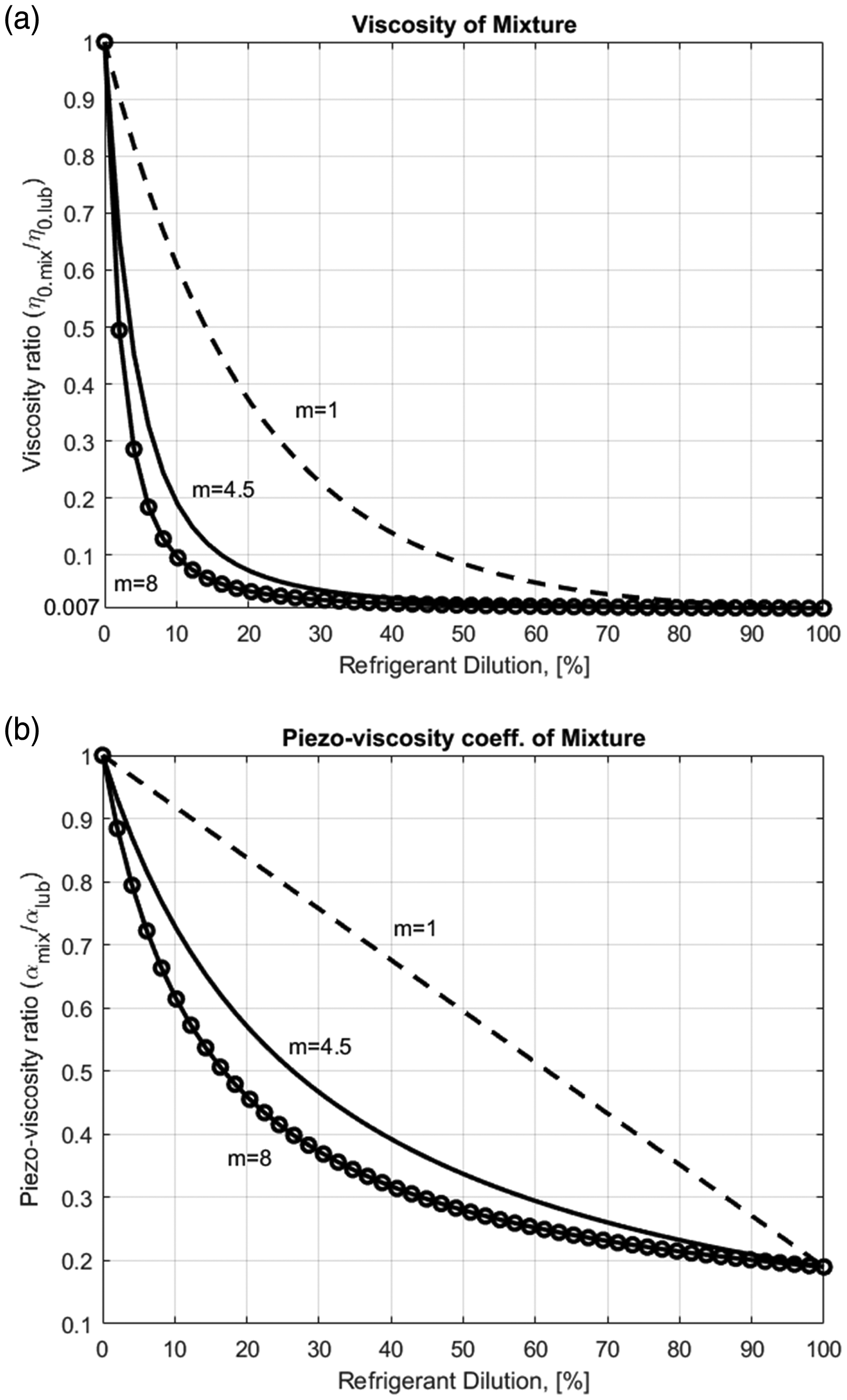
refers to this damage or failure mode as surface distress or surface initiated fatigue, i.e. the failure of the rolling contact metal surface asperities under a reduced lubrication regime and a certain amount of sliding motion causing the formation of (1) burnished areas (glazed; grey stained), (2) asperity microcracks, and (3) asperity microspalls (see Figure 5). All of this will be described herein using the term surface distress. It is well-known that surface distress is the result of the competition between surface fatigue and mild-wear.32,33 Mild-wear (wear at asperity level) modifies the initial topography reducing the asperity heights and also removes fatigued surface layers refreshing the exposed material, thus surface fatigue is delayed.
Surface distress in a raceway bearing surface.
Surface distress modeling
Before testing solutions for a bearing application, often modeling is required to shorten the development time and study the influence of different parameters in the application, lubricant, and bearing. One of the current authors has developed a numerical model for surface distress
34
in rolling bearings that can be applied for the present case of oil–refrigerant mixtures; the flowchart of it is given in Figure 6, the model is described in detail in the reference and will not be presented here, only a short summary will be given. The model requires 3D digitized roughness samples of the two contacting surfaces (inner- or outer-ring raceway and roller or ball), in general several samples are obtained, so several simulations with the different roughness samples representing different raceway locations are required to obtain a fair estimation of life or damage under given conditions. Here, since the focus is only an illustrative case, only one measurement for the inner ring raceway and one measurement for the roller is considered and used all time.
Flowchart of the surface distress model.
34
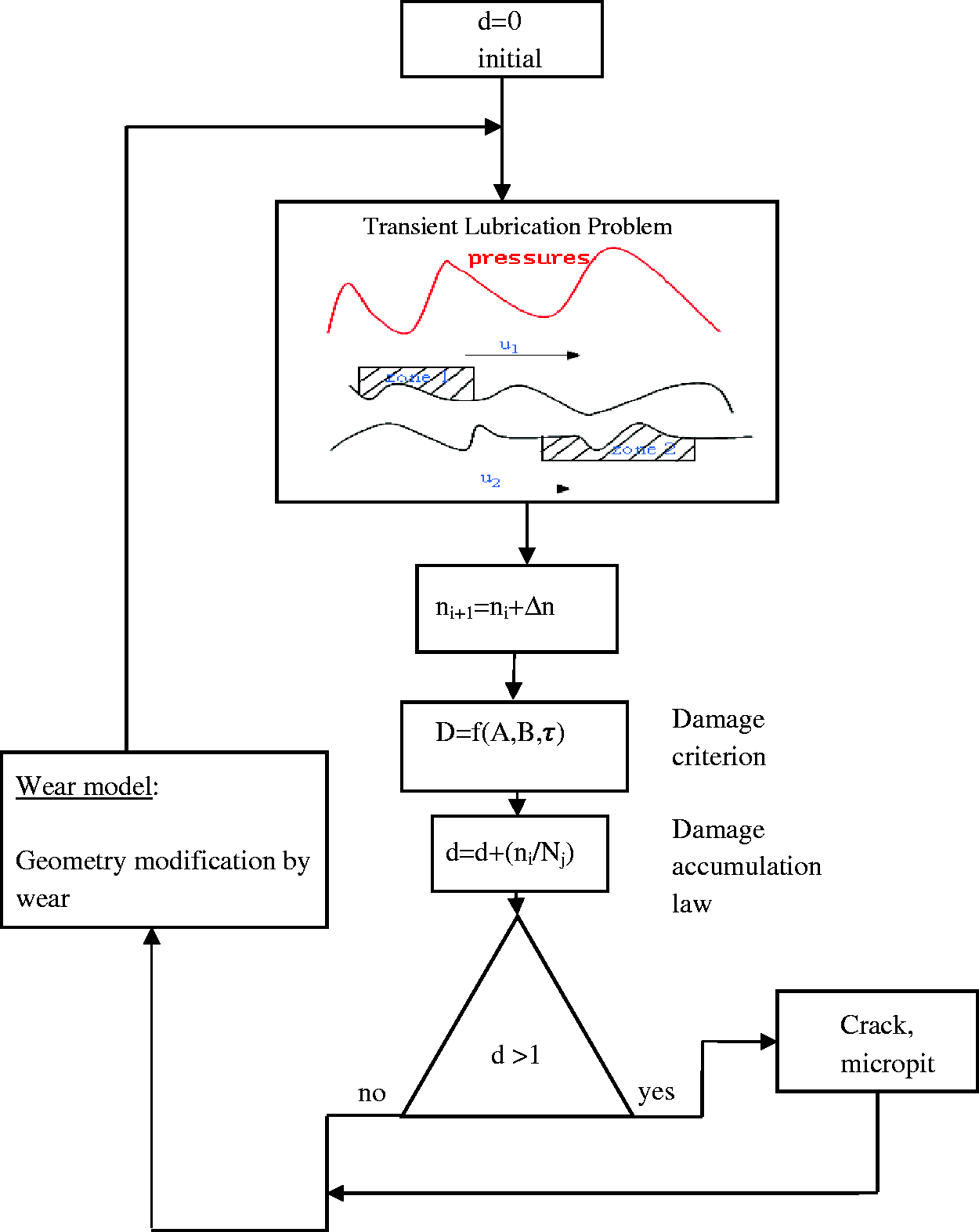
The modeling of the interactions surface-fluid (pressure and surface shear stress) is resolved via a 2D transient Reynolds equation for the fluid and half-space elasticity for the solid. The scheme simulates the relative movement of the microgeometry inside the contact in time for every load cycle. The simulation process begins with the virgin surfaces with no accumulated damage. Once both rough surfaces enter into the contact in the first cycle, the partial transient EHL problem is solved
35
for the different time steps (typically 10) until the exit from the contact. In that time, the local pressure on the roughness follows the Hertzian parabola as it travels within the contact, as explained in Morales-Espejel and Brizmer.
34
The topography is updated only after a certain number of load cycles (in this case 40 times during the whole simulation time) to reduce the computational time (instead of every single load cycle), thus the fatigue damage criterion (e.g. Dang Van36,37) is applied for the current cycle, in the points of the domain where the criterion is not exceeded (
Calculation case for enhanced surface material
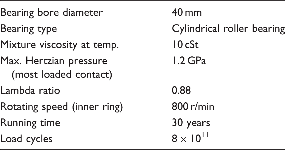
Operating conditions for the surface distress bearing case for the heaviest loaded contact.
The Dang Van36,37 fatigue criterion used by the model requires the two Wöhler curve constants
38
for the surface material used in the bearing. Here, the bulk values provided in Shimizu et al.
39
are used corresponding to hardened bearing steel ASTM 52100, A = −43.0 MPa, B = 1220 MPa. The results of the simulation with the data of Table 2 and these fatigue properties together with the roughness samples of Figure 7 are shown in Figure 8 with the areas marked in red as surface distress, in total about 2.32% of the total area. By comparing Figures 7(b) and 8, it can be seen that the surface distress on the raceway surface develops faster in the areas closer to roughness depressions, more precisely in the areas of higher pressure slopes like in the borders of grinding mark valleys.
40
Roughness sample of the rolling bearing inner ring raceway and roller: (a) 3D view of a spot on the inner-ring raceway R
q
= 0.068 µm; (b) normal view of a spot on the inner-ring raceway R
q
= 0.068 µm; (c) 3D view of a spot on the roller R
q
= 0.090 µm. Surface distress area, as predicted by the model (A
p
= 2.32%) on the bearing raceway for hardened bearing steel ASTM 52100.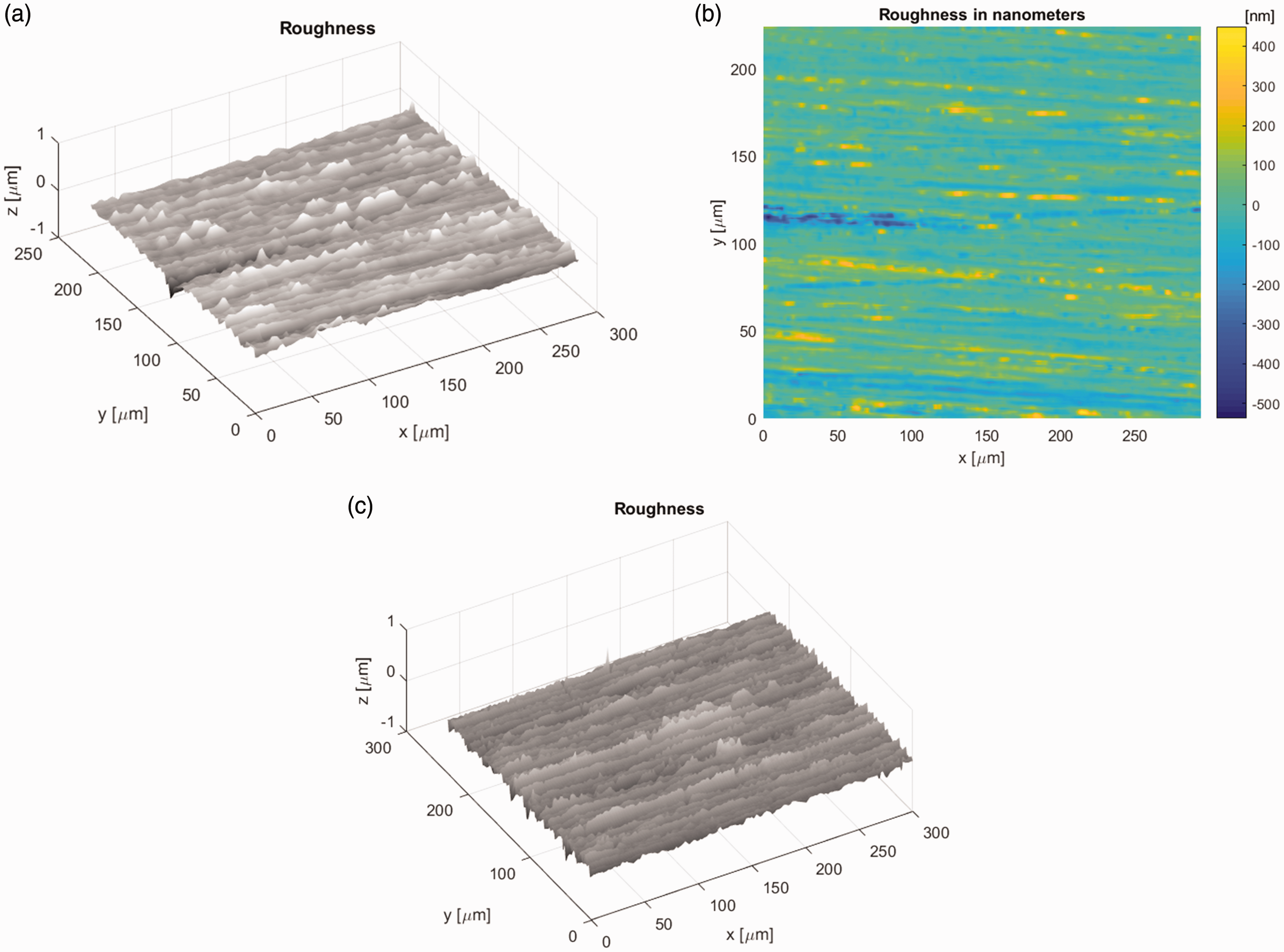
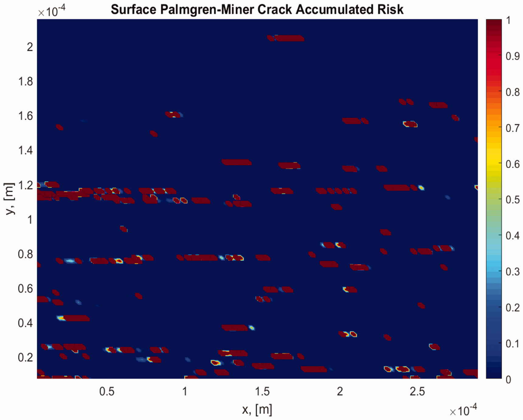
Figure 9 shows some intermediate results in a given simulation time (snap shot) of deformed raceway roughness and hydrodynamic pressure fluctuations generated when the roughness sample is inside the rolling bearing most heavily loaded contact.
Example of deformed bearing raceway roughness (bottom) and EHL pressure fluctuations (top) in a given simulation time, as calculated by the model.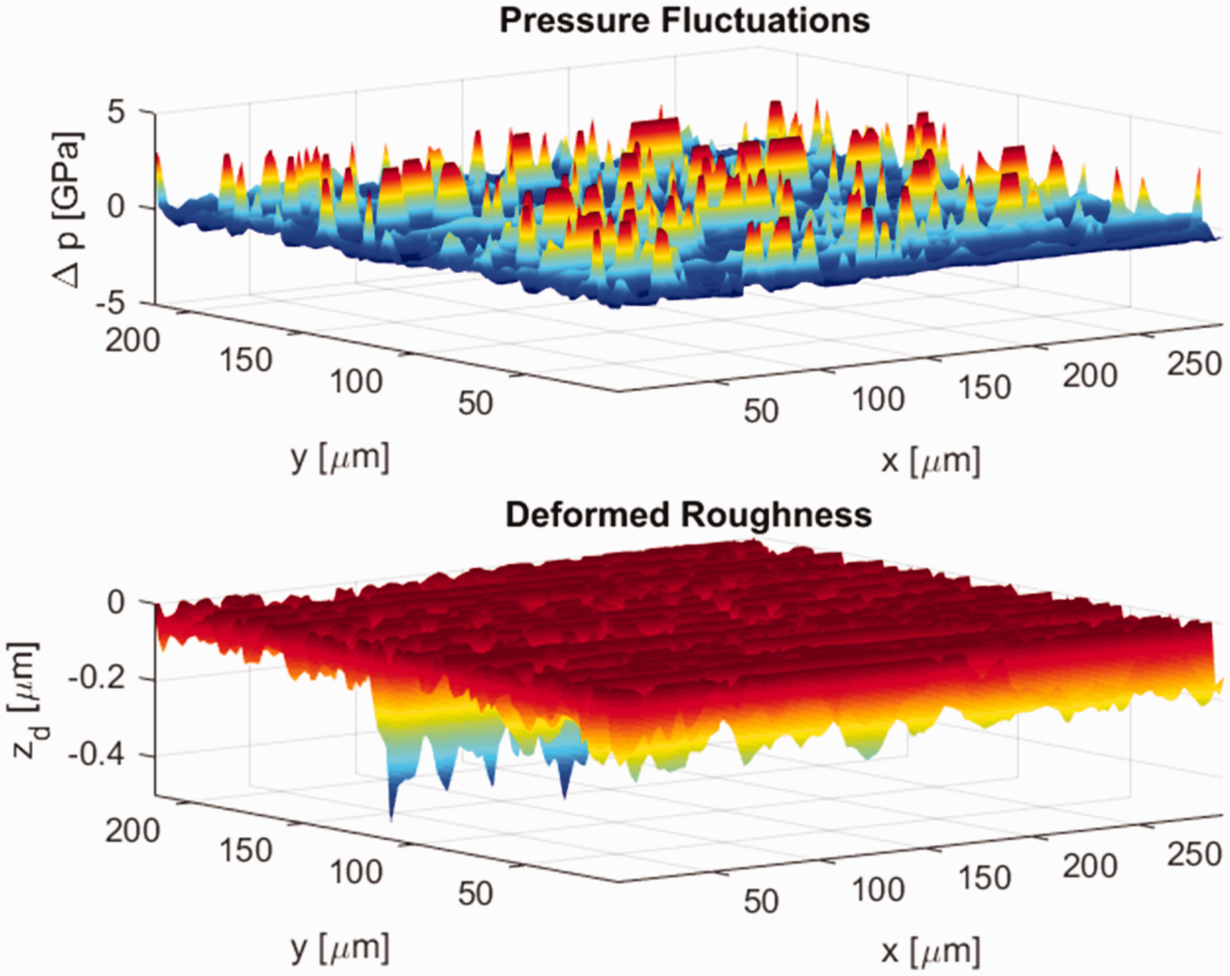
Next, consider that the standard bearing is replaced by a bearing with the HN (carbonitriding) heat treatment as suggested in Gabelli et al.
13
showing higher surface hardness after running-in (which will reduce the wear by up to 45% of the previous value) and will increase the bearing surface fatigue strength sufficient to double the life of the bearing. Thus, emulating the experimental results, by running the present model it is found that an increase in the Wöhler constant B of 22%, will double the life of the bearing, thus the selected constants for the new surface treatment HN are A = −43.0 MPa, B = 1488 MPa, together with a reduction of the wear coefficient by a multiplication factor of 0.45. All other parameters of Table 2 remain unchanged, thus the new results from the model are summarized in Figure 10. This figure shows a very substantial reduction of the surface distress area to negligible values (only 0.38%) despite the reduction of mild wear of the harder surfaces. It can be seen that with the use of advanced tribological modeling the conditions of poor lubrication in rolling bearings can be simulated, including the screening of alternative solutions.
Surface distress area, as predicted by the model (A
p
= 0.38 %) for the surface treatment HN (carbonitriding).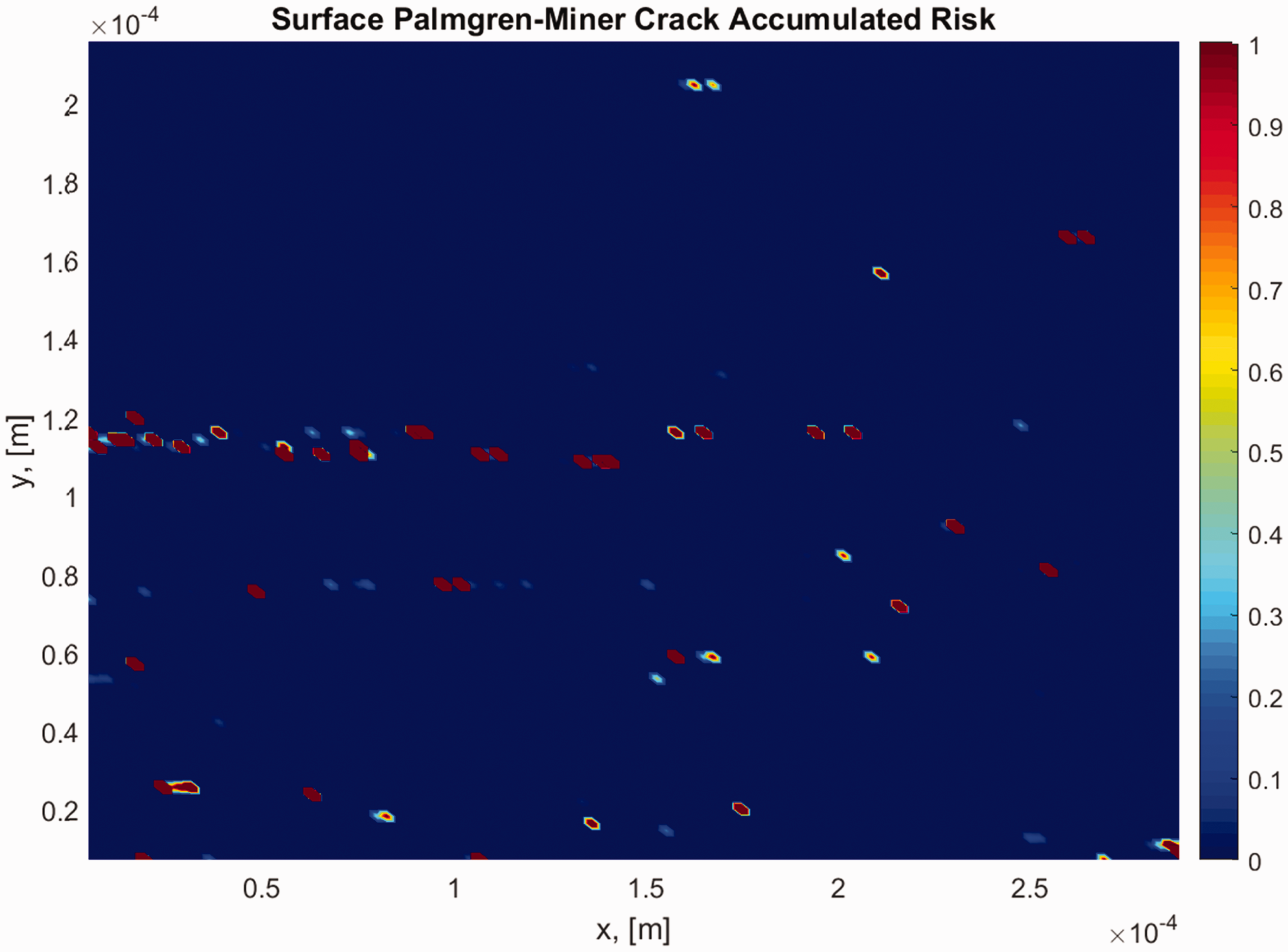
For the case of contamination, the same model can be used to determine the sensitivity of the number and geometry of the indentations, and substantial work has been carried out in this direction by some of the current authors.30,40
Another effective solution for poor lubrication problems is the use of full or semi-hybrid bearings (steel rings and all or a few rolling elements made of ceramic material, Si3N4). The same model has been used 41 to explain how a hybrid bearing, by reducing its boundary friction coefficient, can reach much better performance under poor lubrication conditions than all-steel bearings. The predictions of the model were also confirmed by experiments.
Corrosion-enhanced fatigue
It was discussed above that the most recent refrigerants being explored as possible substitutes of the current ones, for reducing even further the environmental impact, have the tendency to exhibit shorter atmospheric lifetime. In some cases, it means more chemically reactive compounds and often more corrosive to steel or to bearing organic components (e.g. seals, cage, etc.) and even ceramic material. In addition to this, frequent changes of temperature experienced by some parts of the compressors could favor the ingress of moisture in the bearings, and the corrosion environment in the bearings can then be worsened. Therefore, it is expected that a new challenge for rolling bearings in refrigerant compressors is the exposure to some degree of corrosion. Very mild corrosion will manifest only as a noticeable increase of wear or mild wear in the bearing. If corrosion is important, then some corrosion pitting can appear, which can be distinguished from the “mechanical” micropitting or surface distress discussed above by careful examination of the features under the microscope. It is believed that this corrosion pitting not only will enhance the local stress concentration but also could weaken the surface fatigue strength of the surface. One semi-empirical way to model it using the above surface distress model is by reducing the value of the Wöhler constant B to a value that matches the observations. Otherwise, the actual corrosion phenomenon would need to be modeled.
In PRL conditions with the presence of hybrid bearings in order to reduce the risk of corrosion, some additive or preservative can be used in the bearing or lubrication system to protect the bearing surfaces from the chemical attacks. Special stainless bearing material (as described in the PRL section) already provides some good protection against corrosion. Besides, proper earthing systems for the area where the bearings are located in the compressor avoids electrostatic potentials from the friction between the refrigerant and the moving parts of the bearings. Otherwise, the build-up of electrostatic charges might favor corrosion attack on the bearing surfaces. Finally, to reduce the risk of galvanic corrosion (bi-metallic corrosion) the use of brass and other metallic cages should be minimized or used with caution. 42
Technological solutions
Surface treatments in conventional rolling bearings
For oil–refrigerant mixtures under poor lubrication and/or high contamination, a heat treatment that has large potential for rolling bearings is nitriding and carbonitriding. The latest one is an added surface heat treatment with the addition of ammonia to the standard gas carburization process. This introduces N and C atoms diffusing into the surface steel, improving the fatigue strength and reducing wear. Carbonitrided (HN code) 13 bearings have been tested and compared with normal heat-treated bearings in harsh contaminated conditions. Wear rate was reduced to about 45% of the normal bearings and bearing life was roughly doubled for those particular test conditions. Also, the surface distress model was used to simulate the behavior and provide understanding.
As explained in Gabelli et al., 13 for standard (ASTM 52100) hardened and tempered steel bearings, the permitted maximum content of retained austenite is 15 vol.% and the diameter of the residual carbides is usually 1 µm or less. The hardness is in general above 62 HRC. The carbonitriding surface hardening of the SAE 52100 rings produces a structure at the ground surface, which consists of martensite strengthened by carbon and nitrogen, with a higher retained austenite content than in a standard through hardened bearing ring and a proportion of enlarged carbides with diameters of more than 2 to 3 µm. Along this, there is a positive modification of the surface residual stresses. All this substantially improves the strength of the surface by providing toughness and higher wear resistance.
Semi-hybrid rolling bearings
It has been verified by testing 14 that steel rolling bearings, which contain at least one rolling element made of ceramic (Si3N4) improve substantially their performance under poor lubrication and high contamination conditions, therefore the next line of defence after nitriding or carbonitriding for lubrication with oil–refrigerant mixtures should be this type of rolling bearings so-called as semi-hybrids. The working mechanism is similar to hybrid bearings, explained already in Brizmer et al. 41 and Vieillard et al. 43
Coatings
In-house experiments have proven that most of the porous coatings flake-off in the presence of high concentrations of refrigerant within the lubricant (for sure in PRL conditions). Since the refrigerant tends to penetrate the coating through the pores to reach the steel surface, sometimes it brings about corrosion on the steel surface below the coating. Thus, if a coating has to be chosen in harsh oil–refrigerant lubrication conditions, it is recommended to select a sacrificial coating that will mainly help to run-in the surfaces improving the tribology and smearing itself onto the steel surfaces. In this way, it will also protect them from mild chemical attacks (mild corrosion), rather than pretending staying untouched covering uniformly the steel surface. This is the case for black oxide coating, 44 which could be a rolling bearing performance improver in mild severity conditions of poor lubrication with oil–refrigerant mixture. An alternative to avoid corrosion is zinc-coated bearings.
In milder refrigerant dilution rates other coatings can be used, providing the bearings with some protection. This is the case for special DLC (NoWear™) with and without porosity seal, made to endure poor lubrication conditions and to fight adhesive wear. Other anti-wear solutions include manganese phosphate coating and titan molybdenum disulfide coating (or triple M) with very low friction coefficients.
Discussion
The present paper attempts to summarize the current rolling bearing technology status for the application of refrigerant compressors, where the lubrication with an oil–refrigerant mixture is common practice. It is observed that all-steel bearing technologies applied up to date for the present refrigerants and typical dilution rates up to 20% refrigerant content are being challenged by more chemically active post-Kyoto protocol new refrigerants and dilution rates higher than 30% in parts of the duty cycle. Besides this, a new technology pioneered by the current authors which allows the rolling bearings to be lubricated solely with refrigerant (the so-called PRL technology) is observed to be developing well in the industry.
As a graphical summary of the application of the different rolling bearing technologies, the authors propose the schematics of Figure 11 to describe the possible usage ranges and technology sophistication level of the different rolling bearing technologies discussed in the current paper as a function of the refrigerant dilution rate in the oil.
Proposed rolling bearing technology applicability as a function of the refrigerant dilution rate in the oil.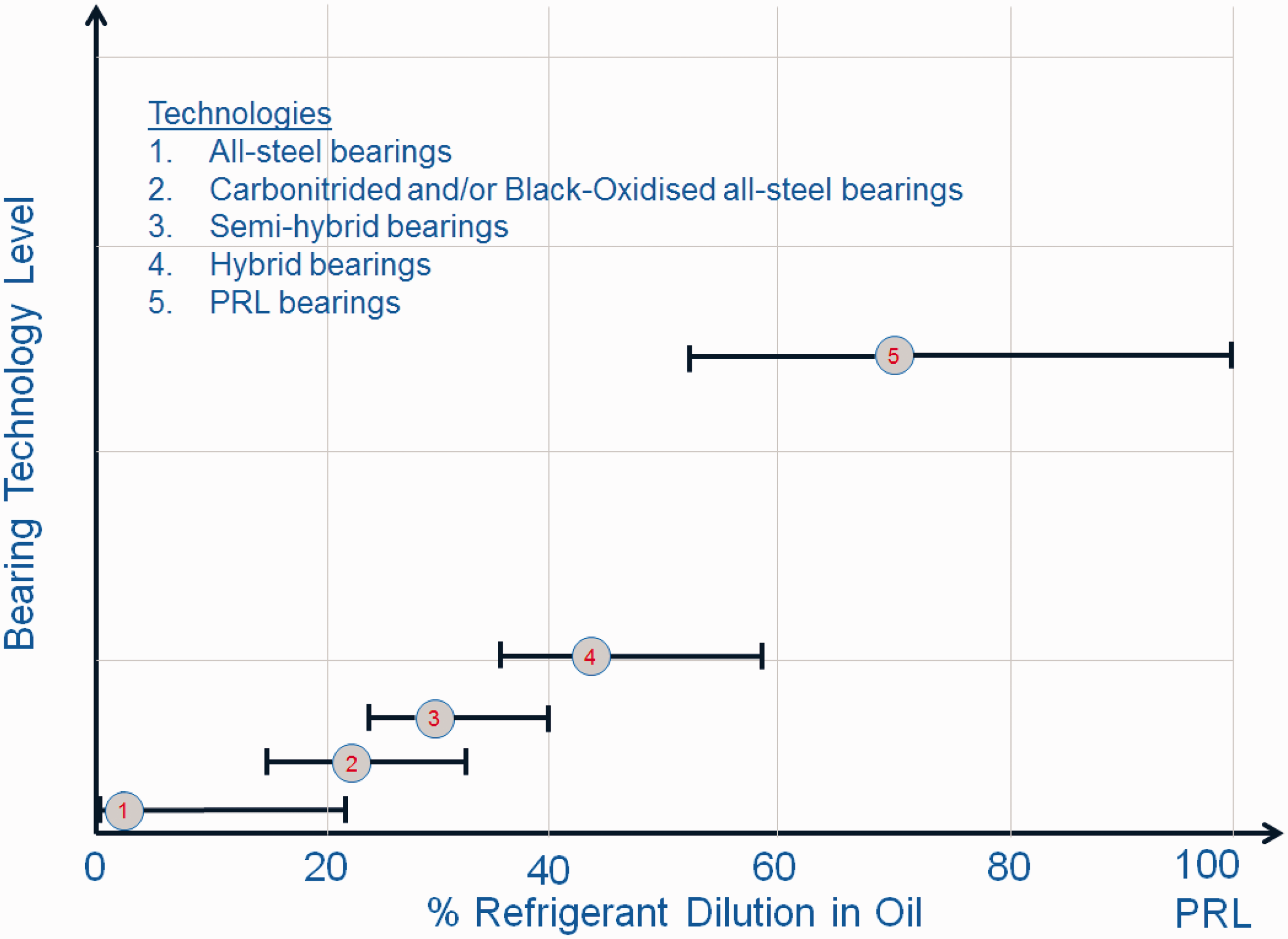
Notice that the ordinate in Figure 11 (bearing technology level) represents a qualitative scale where no values are given. But it shows, in a relative level and according to the experience of the authors, the technology degree that is required for every product to be successful and reliable.
Conclusions
Different compressor designs and bearing arrangements were briefly discussed. The main failure mode of rolling bearings lubricated with refrigerant–oil mixture (surface distress) was discussed in detail. A model to predict surface distress from poor lubrication conditions was explained with the application to carbonitrided bearings. Some aspects of corrosion fatigue were mentioned and lubrication aspects of oil–refrigerant mixtures were discussed in detail with emphasis on film thickness estimation and effects on bearing life. Besides, PRL technology is summarized and different technological solutions to mitigate the old and new challenges to rolling bearings lubricated with oil–refrigerant mixtures are discussed.
The following conclusions can be drawn from this study:
The current all-steel rolling bearing technology is currently challenged by the arrival of new, more environmentally friendly refrigerants in the industrial compressor sector, which bring higher refrigerant dilution rates and more chemically active compounds. As a response to this challenge, new rolling bearing technologies are proposed, like the use of special heat treatments, semi-hybrid, and hybrid rolling bearings. For the more advanced technological challenge of PRL, special hybrid bearings have proved successful in industry. Better understanding of the lubrication mechanisms and failure inception via modeling, experiments, and testing is proposed to face the new challenges of rolling bearings in refrigerant compressors.
Footnotes
Acknowledgment
The authors wish to thank Dr Stefan Lammens, SKF Engineering and Research Centre Director, for his permission to publish this article.
Declaration of Conflicting Interests
The author(s) declared no potential conflicts of interest with respect to the research, authorship, and/or publication of this article.
Funding
The author(s) received no financial support for the research, authorship, and/or publication of this article.