
Abstract
In this study, an investigation has been conducted to fully characterise for the first time the tribological benefits of adding two different types of chemical vapour deposition (CVD) coatings to silicon aluminium oxynitride milling inserts with a chemical composition of (Si3N4 + Al2O3 + Y2O3), known by the trade abbreviation ‘SiAlON’, typically used to cut difficult to machine materials such as Inconel 718. The experimental tests compared the tool life, material removed and wear resistance of the two different CVD coated inserts against that of uncoated SiAlON ceramic milling inserts. Coating A was a multilayer CVD coating and had a composition of (TiN + TiCN + Al2O3), Coating B was a bilayer CVD coating and had a composition of (Al2O3 + TiN). It was determined that at 900 m/min the uncoated SiAlON ceramic milling inserts exhibited the least amount of wear and variation in cutting force when milling precipitation hardened Inconel 718 samples. Coating A demonstrated significantly lower adhesion to the SiAlON substrate but had higher tool life and material removal rates, Coating B demonstrated excellent adhesion to the SiAlON substrate. The interfacial bonding of Coating B allowed for much higher adhesion to the substrate, but it suffered from much lower tool life and higher rates of rake and flank face wear. The flank wear measurements concluded a cutting speed of 900 m/min to be the optimum cutting speed for machining Inconel 718 with uncoated SiAlON ceramic milling inserts.
Introduction
Inconel 718 is regularly defined as a difficult material to machine due to its high propensity to work harden, its toughness and its relatively low thermal conductivity concentrates the elevated temperature in the cutting zone. As stated by Arunachalam and Mannan,
1
the material maintains a mechanical strength of approximately 1170 MPa up to 650°C and thus high specific cutting forces are required. They also conclude that beyond 650°C, the thermal stability of the
Despite the continuous development of silicon nitride based (SiAlON) ceramic cutting tools over the last 40 years, SiAlON ceramic milling cutting tools have struggled to achieve significant acceptance by industry and increase their market share in the cutting tool market. 4 Even with improved mechanical properties and better wear performance, SiAlON ceramics still have a reputation of having poor fracture toughness and substantially lower tool life in comparison to typical tungsten carbide or PCBN milling inserts. Several authors5–8 have concluded that machining parameters (cutting speed, feed per tooth, depth of cut, minimum chip thickness) all influence the amount of flank wear, rake face wear and notch wear that the inserts experience.
The magnitude of wear directly affects the performance and tool life of ceramic cutting tools when machining nickel-based alloys such as Inconel 718. Molaiekiya et al.9,10 established the importance of optimising the parameters for using ceramic cutting tools for machining nickel-based alloys. That said, during the machining process SiAlON ceramic milling inserts will suffer from a variety of wear mechanisms which contribute to insert failure. The primary wear mechanisms for SiAlON ceramic milling inserts are flank, rake, crater and depth of cut notch wear as described by both Zheng et al. 11 and Shalaby and Veldhuis. 12
In addition to the primary wear mechanisms, secondary wear mechanisms such as micro-cracks, chipping, lamellar flaking together with thermo-mechanical wear and diffusion wear also collectively contribute to the degradation of cutting tool and the life of the tool.13–15
These secondary wear mechanisms are due to the high cutting forces being transmitted through the inserts, which in turn causes the rake face of the insert structure to shear along the grain boundary, Li et al. 16 suggests that high cutting speeds in excess of 500 m/min in accordance with the feed rate of 0.06 mm/rev should be adopted to minimise insert flank wear and the required specific cutting force by exploiting the thermo-mechanical softening of the workpiece that take place at higher cutting speeds. Higher induced material softening takes place above 650 m/min, which ultimately has a positive effect on tool life and flank wear rates as discovered by Zha et al. 17
To date the most relevant research that has been published has focused on utilising coated SiAlON ceramic milling inserts for milling cast iron and steels, which is the main driver of this research. Earlier turning and tribological studies18–23 that have utilised coated ceramic indexable inserts, have all stated that applying protective physical vapour deposition (PVD) and chemical vapour deposition (CVD) wear resistant coatings will improve the wear resistance and overall cutting performance of SiAlON inserts when machining steels and cast irons. A recent study conducted by Mikuła et al. 24 also concluded the benefit of depositing a protective PVD coating onto SiAlON inserts when turning grey cast iron EN-GJL-250. Dobrzański and Pakuła 25 conclude that the improved surface topology improves the insert resistance to micro cracking and thermo mechanical wear. In addition to this, Sun et al. 26 and Mahesh et al. 27 all suggest that diffusion wear is one of the mechanisms contributing to flank and rake face wear.
Furthermore, Heikinheimo et al. 28 state that diffusion reactions between silicon nitride-based (SiAlON) ceramics and nickel-based alloys take place at 1100°C with the formation of liquid phases. Addhoum and Broussaud 13 also conclude that silicides, carbides and potentially nitrides, are created due to the complex interaction mechanisms and chemical reactions that take place between the silicon nitride-based ceramic cutting tool and the nickel-based alloy chip. The process of applying a coating to SiAlON is complex. As a result Konstantiniuk et al. 29 concluded that controlling the coating process condition and texture of the α-Al2O3 coatings, is highly important in attaining repeatable results that deliver high wear resistance and cutting performance.
There has been little research looking at the effects of milling Inconel 718 with coated SiAlON milling inserts and the effects on chip formation. Therefore, the focus of the work presented here is to fully characterise the benefits of adding a protective coating to SiAlON ceramic milling inserts for the purpose of machining precipitation hardened Inconel 718. Uncoated and CVD coated SiAlON ceramic milling inserts have machined aged Inconel 718 samples at cutting speeds of 700, 800, 900 and 1000 m/min. This approach was conducted to ascertain what is the optimum cutting speed for machining Inconel 718; and to see if protective CVD coatings would dilute the effects of wear mechanisms such as diffusion wear which would improve tool life and machining performance.
Experimental details
Experimental setup
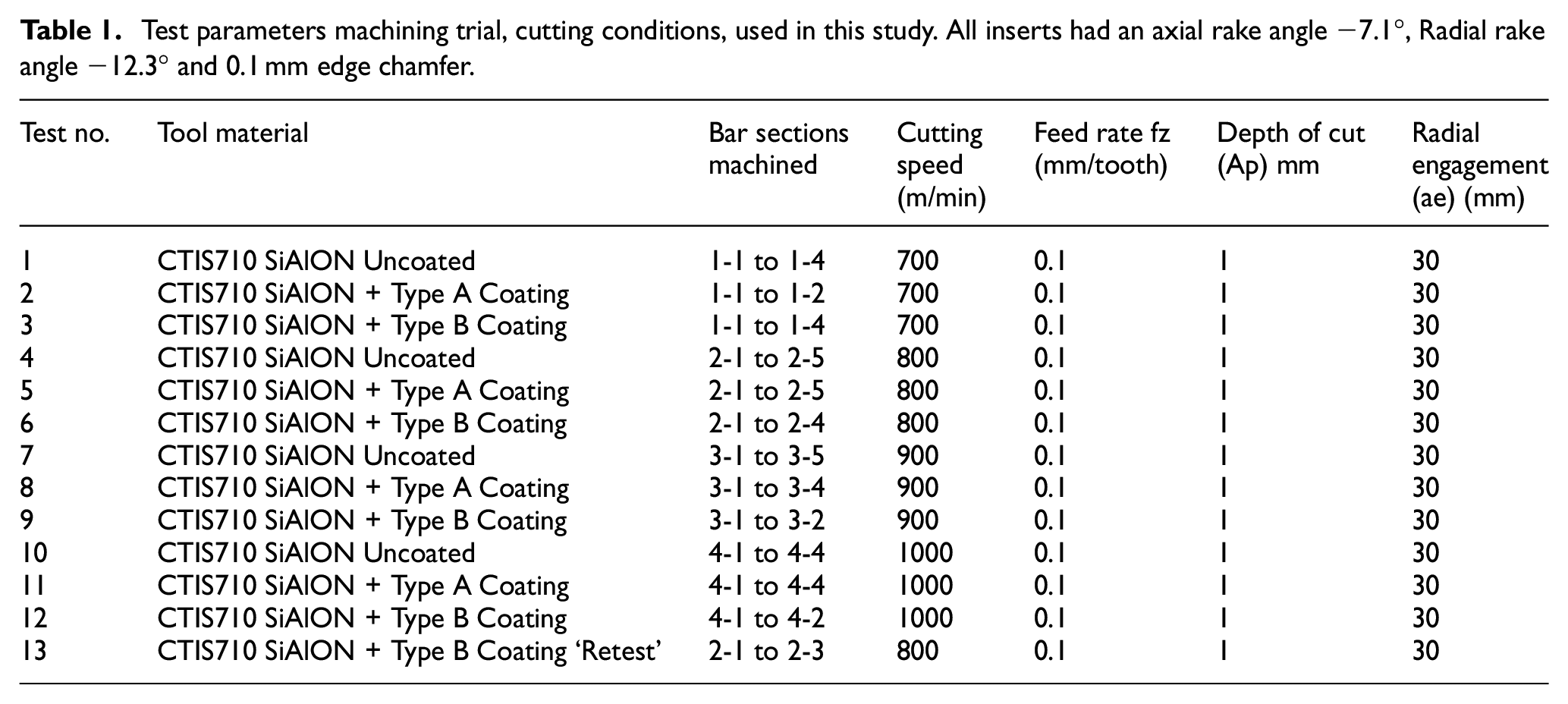
In the study, the workpiece material was solution treated and aged nickel-based superalloy Inconel 718 (AMS5663). The 13 test samples were 60.0 mm diameter × 86.0 mm long round bars with machined flats at one end give a positive work holding location and thus securing the workpiece. The test number, machining parameters and test sequence which have been used in the machining trials are listed in Table 1.
Test parameters machining trial, cutting conditions, used in this study. All inserts had an axial rake angle −7.1°, Radial rake angle −12.3° and 0.1 mm edge chamfer.
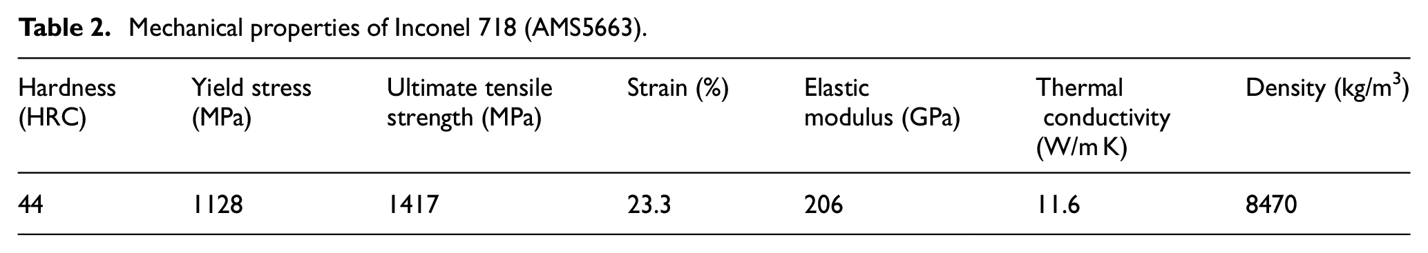
The approximate mechanical properties of the age hardened Inconel 718 samples were obtained from ASTM E140 and ASTM A370 and can be seen in Table 2.
Mechanical properties of Inconel 718 (AMS5663).
Both coatings were applied at the manufacturer’s Ruette facility in Austria on a Sucotec (SCT600TH) industrial-scale CVD machine. The oxide coatings were deposited at a temperature of 1000°C, the deposition rate was 1–2 µm per hour. A MaxiMill A262.40.R.04-1204 insert holder and BT40 spindle were utilised for all the machining tests, which had a maximum cutting diameter of 40.0 mm. Four inserts were used in each milling test. Material properties of the cutting tool inserts are shown in Table 3.
Physical properties of uncoated and CVD coated SiAlON ceramic milling inserts used in this study.
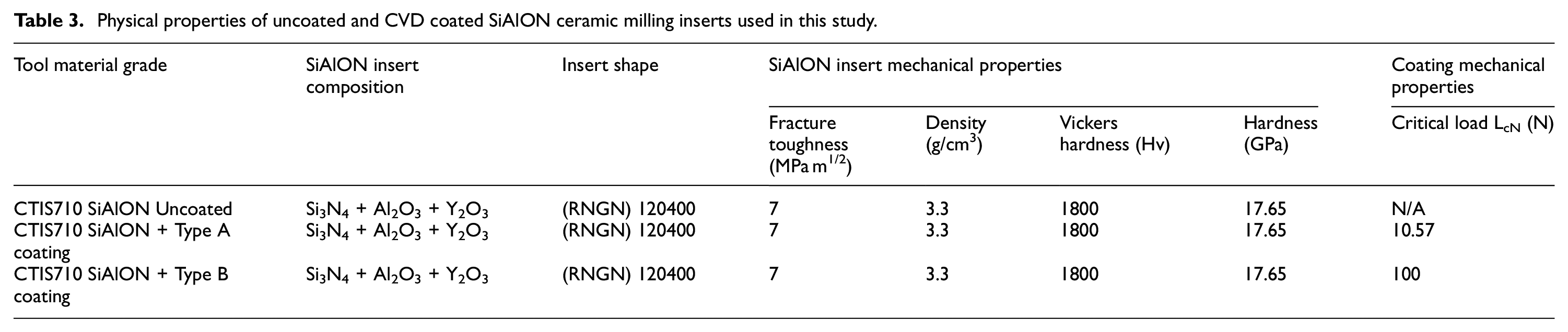
The machining operations for this study took place on a 26 kW DMG Mori NVX5080 three axis machining centre. The NVX5080 has a max standard spindle speed of 15,000 r/min. Uncoated CTIS710 SiAlON ceramic milling inserts and two types of CVD coated CTIS710 SiAlON milling round button inserts were used in milling tests. The coatings used were a TiN + TiCN + Al2O3 multilayer coating (Coating A) and an optimised ceramic coating Al2O3 + TiN (Coating B). Coating B was selected for this machining trial as it had been optimised for CVD coating SiAlON ceramics. The Al2O3 interfacial layer in Coating B was selected as it would attain high adhesion to the SiAlON substrate, retain high hot hardness and exhibit high resistance to thermochemical wear. The TiN outer layer for Coating B was selected as it would exhibit high wear resistance. Coating A was selected as a comparative CVD coating for the machining trial. Coating A is typically used to protect carbide milling inserts during superalloy milling operations.
Experimental procedure
Up-milling operations were conducted under dry conditions and no through air cooling was applied to the cutting tool due to a limitation of the test platform, which might have caused fluctuation in cutting temperature. The 13 samples were machined at cutting speeds ranging from 700 to 1000 m/min with a constant feed per tooth (fz) of 0.1 mm/tooth and constant axial depth of cut (Ap) of 1.0 mm in the Fz-direction and the radial engagement (Ae) of 30.0 mm. The feed per tooth, depth of cut and the 30.0 mm radial engagement were selected to maintain chip thickness (Hex) as constant where possible. For the removal of each bar section, the metal removal volume was 33.93 cm3, a maximum of 5 bar sections were removed for each of the cutting speeds with the three different inserts. A new set of four inserts was used for each of the four cutting speeds.
The machine setup that was utilised for capturing the cutting force signal data that was generated at the four cutting speeds of 700, 800, 900 and 1000 m/min is shown in Figure 1(a). Figure 1(b) and (c) shows the Zeiss V8 Discovery microscope set-up that was utilised to capture rake and flank wear (Vbb) measurements.
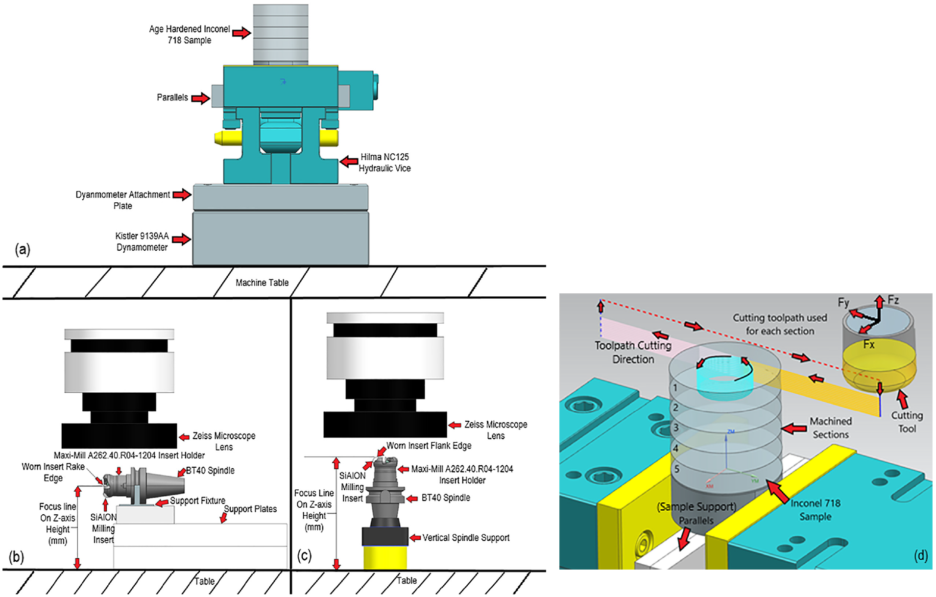
(a) Machine trial work-piece setup on the DMG Mori NVX5080 machining centre, (b and c) Zeiss set-up for rake and flank wear measurement and (d) Siemens NX CAM model assembly 3D view of cutting tool path and the five sections (e.g. 1-1–1-5 in Table 1) of the sample bar.
A Kistler 9139AA dynamometer was used to measure cutting forces during the machining process with sample rate at 20 kHz over the course of 120 s. This sampling rate was selected as it captured sufficient data points per revolution regarding tool passing frequency for the four cutting speeds.
The custom cutting tool path shown in Figure 1(d) was designed to minimise fluctuations in maximum chip thickness (Hex) and specific cutting forces by programming the cutting tool to tangentially engage and exit from cut, which resulted in a gradual increase and subsequent decrease in radial immersion of the cutting tool. Each of the machined bar sections involved machining 12-off 1.0 mm depth of cut (Ap).
Maintaining the maximum chip thickness at a constant level is necessary to avoid fluctuations of tensile and compressive stress on the rake face, which contribute to premature tool failure. Equation (1) was used to calculate a value that would prevent shocking the cutting tool during the machining process of each 1.0 mm depth of cut (Ap), the insert diameter is represented by (IC) and the feed rate (fz). Equation (1) was used to calculate a value that would prevent shocking the cutting tool during the machining process of each 1.0 mm depth of cut (Ap), the insert diameter is represented by (IC) and the feed rate (fz).

The experimental process and machining parameters were selected in order ascertain different tool wear characteristics and tool life at four different cutting speeds. The four cutting speeds were selected based on the technical advice from the cutting tool manufacturer Ceratizit UK and Ireland Ltd. The feed rates and depth of cut were selected based upon maximum chip thickness (Hex) values which were 0.053. The principal aim was to find the best cutting speed, which could be used in future machine trial research.
Tool life criteria
The tool life criteria for this machining trial were selected to gain a greater understanding of the true machining tool life limit within which these three SiAlON ceramic inserts can perform. Traditionally SiAlON ceramic milling inserts are typically changed once flank wear (Vbb) has surpassed 1.0 mm. The basis for the selection of the wear criteria for this experimental work was influenced by previous experimental studies.30–32 These three studies highlighted that ceramic milling inserts can still perform their function of removing material during a machining process, even if the inserts have sustained significant amounts of the flank and rake face wear. Therefore, based on the flank wear results which have been recorded in these three studies the following tool life criteria was selected. Once flank wear for any of the four inserts had surpassed 2.5 mm (Vbb), or the insert has sustained significant damage on the rake face, the test was stopped. The distance travelled by the cutting tool, volume of metal that has been removed and a flank wear measurement is captured after each bar section has been removed. The following tool life criteria was used:
The maximum flank wear (Vbb) land reaches 2.5 mm, once this value is surpassed the test is stopped to prevent tool failure.
Chipping (flaking) or premature failure occurs after the first cut of Inconel 718 sample had been machined.
Results and discussion
For each test to be deemed successful, 169.64 cm3 of material had to be removed as this would have consumed all five sections of the Inconel 718 sample as can been seen in Figure 1(d). The test number, machining parameters and test sequence which have been used in the machining trials are stipulated listed in Table 1.
The material was machined away in five 12.0 mm long sections as seen in Figure 1(d). Once the section had been successfully machined away, the tool was removed from the machine and the inserts kept in position so that insert flank and rake face wear measurement data could be gathered using the optical microscope. Each of the five sections of material that were removed accounted individually for 33.929 cm3 of the total volume of material removed.
Influence of uncoated and coated inserts on cutting force
With the aim of identifying if a protective coating can improve the machining performance, tool life and wear characteristics of SiAlON ceramic milling inserts. To identify if a protective coating would improve the wear characteristics of SiAlON ceramic milling inserts. The two CVD coated SiAlONs tool life and wear performance was compared to that of uncoated SiAlON milling inserts. From the data that was attained a series of wear patterns emerged. At the start of machining, bar sections 1-1, 2-1, 3-1 and 4-1, the stability of the Inconel 718 workpiece is at its lowest. What counters this loss of stability is the amount of cutting force necessary to machine each bar section, which is also at its lowest as the inserts have not sustained any significant amounts of wear in the early stages of the test. Figure 2(a) and (b) shows the level of average cutting force in the Fx-axis, Fy-axis and Fz-axis throughout the machining trial.
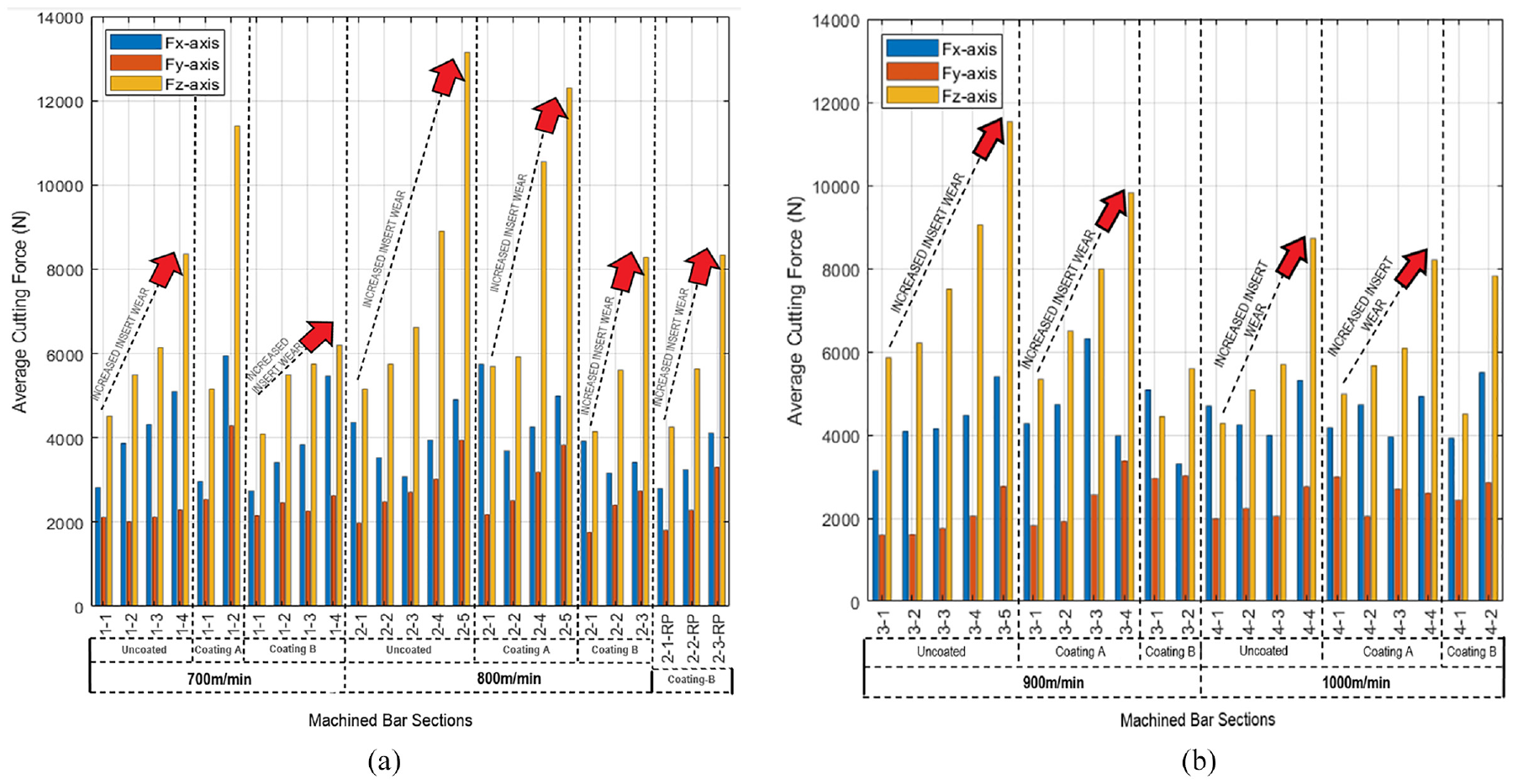
(a) Average cutting force versus machined bar section at 700 and 800 m/min and (b) average cutting force versus machined bar section at 900 and 1000 m/min.
The other reason for the high cutting forces in the Fx, Fy and especially the Fz axis when compared to other research conducted by Molaiekiya et al. 9 and Tian et al., 5 is down to the size of cut and radial engagement (ae). All the bar sections were machined with an initial full radial engagement of 30.0 mm, which stays constant for about two-thirds of the cut and then the radial immersion reduces as each test cut travels through a full 360° and exits out of cut in the Fy-axis direction. The levels of resultant cutting force which the three types of SiAlON experienced, and the relationship between the average resultant cutting force and the change in cutting speed is also shown in Figure 3.
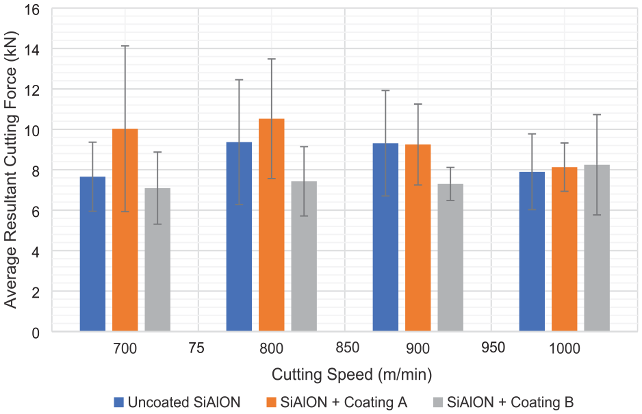
Resultant cutting force versus cutting speed (m/min) for uncoated SiAlON milling inserts and for Coating A and Coating B.
Throughout the machining trial there has been a gradual increase in cutting force during the machining the bar sections which is presented in Figure 2(a) and (b). The gradual increase in cutting force correlates with the progressive level of wear which the inserts have sustained when machining each bar section. The gradual increase in insert flank face wear is represented in Figures 4(a–h), 5(a–l) 6(a–h) and 7(a–h). At the lower cutting speeds of 700 and 800 m/min the workpiece material maintains higher hardness during the cutting process, as the workpiece has not undergone sufficient thermal softening in the chip/tool interface to reduce the yield strength of the workpiece material. The lack of thermal softening is shown in both Figures 2(a and b) and 3, where the uncoated and Coating A inserts required more cutting force to remove each cut and meant that the uncoated inserts and the Coating A inserts experienced higher mechanical shock between the tool and the workpiece. The Coating B inserts experienced lesser fluctuations in the average resultant cutting force at cutting speeds ranging from 700 to 900 m/min, which is likely due to the low friction characteristics of the titanium nitride outer coating. However, this lower cutting force requirement changed when the cutting speed was increased from 900 to 1000 m/min. Figures 2(a and b) and 3 highlights the impact of the thermal softening effect in the chip/tool interface, which led to a large reduction in the hardness and the shear stress which is necessary to remove each cut of workpiece material. This in turn also led to large reductions in the level of mechanical shock between the tool and workpiece which was evident by the sound of each cut.
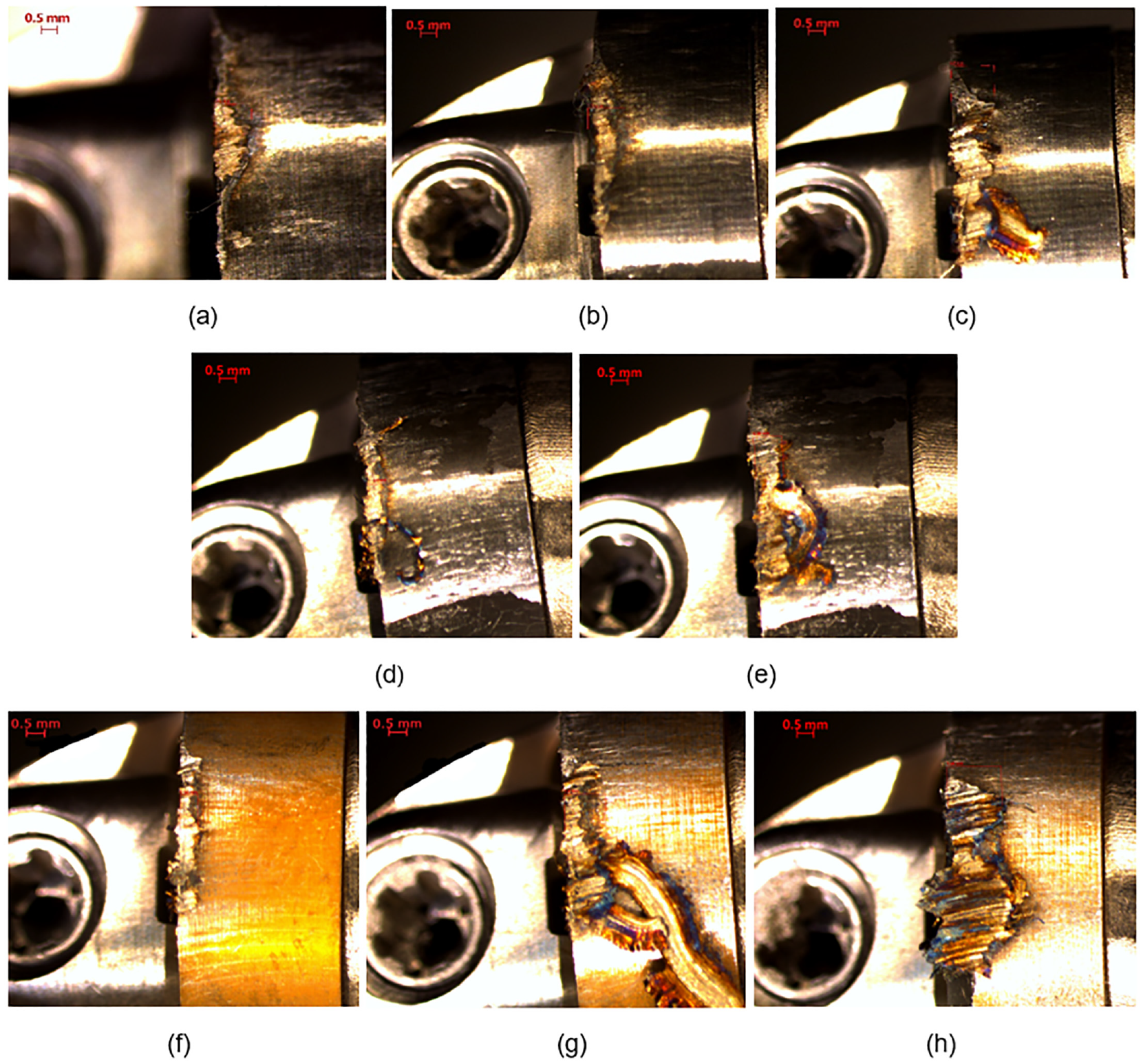
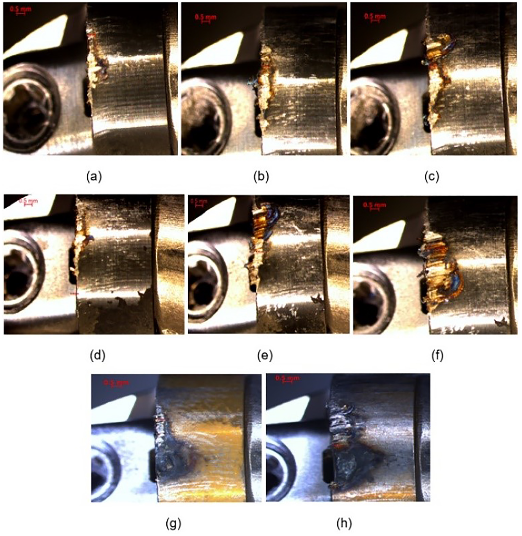
Flank wear visible (a-c) 700 m/min-Bar-Section-1.1-1-3-insert-Uncoated-insert-1 flank face the material removed is 101.80 cm3, flank wear visible (d-e) 700 m/min-Bar-Section-1.1-1-2-insert-Coating-A-insert-3 flank face the material removed is 67.86 cm3, flank wear visible (f-h) 700 m/min-Bar-Section-1.1-1-3-insert-Coating-B-insert-4 flank face the material removed is 101.80 cm3.
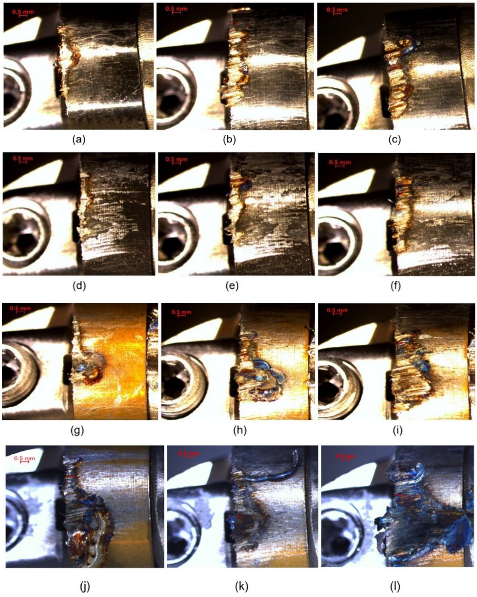
Flank wear visible (a–c) 800 m/min-Bar-Section-2.1-2-3-insert-Uncoated-insert-3 flank face, flank wear visible (d–f) 800 m/min-Bar-Section-2.1-2-3-insert-Coating-A-insert-3 flank face (d and f), flank wear visible (g–i) 800 m/min-Bar-Section-2.1-2-3-insert-Coating-B-insert-3 flank face, flank wear visible (j–l) 800 m/min-Bar-Section-2.1-2-3-insert-Coating-B-insert-3 flank face. For all the material removed is 101.80 cm3.
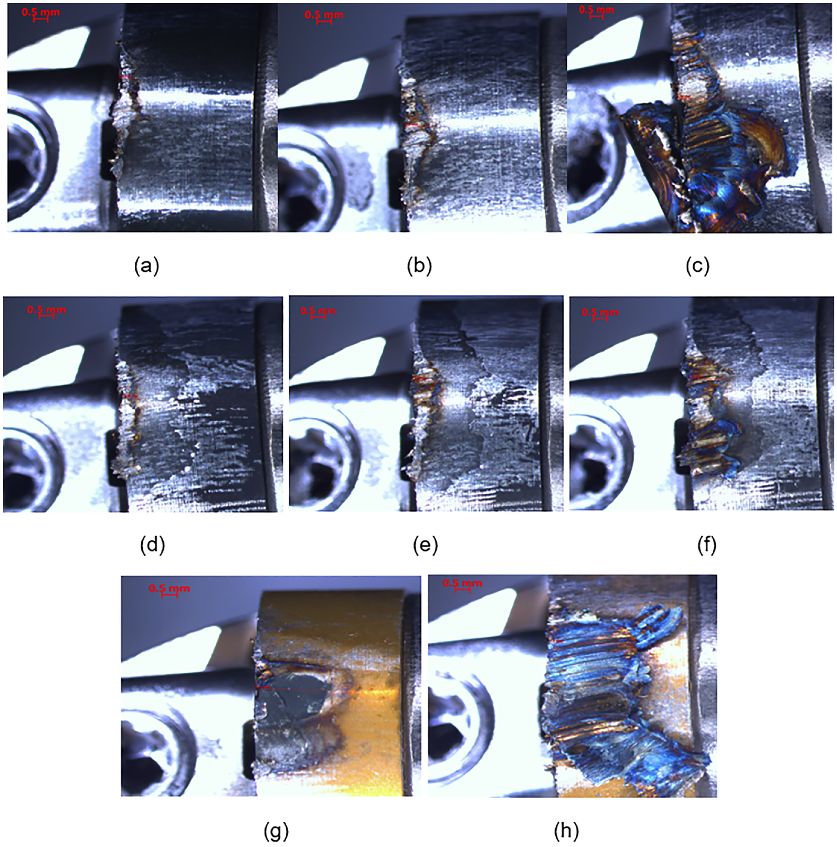
Flank wear visible (a–c) 900 m/min-Bar-Section-3.1-3-3-insert-Uncoated-insert-2 flank face the material removed is 101.80 cm3, flank wear visible (d–f) 900 m/min-Bar-Section-3.1-3-3-insert-Coating-A-insert-2 flank face the material removed is 101.80 cm3, flank wear visible (g and h) 900 m/min-Bar-Section-3.1-3-2-insert-Coating-B-insert-2 flank face the material removed is 67.86 cm3.
Flank wear visible (a–c) 1000 m/min-Bar-Section-4.1-4-3-insert-Uncoated-insert-3 flank face the material removed is 101.80 cm3, flank wear visible (d–f) 1000 m/min-Bar-Section-4.1-4-3-insert-Coating-A-insert-4 flank face the material removed is 101.80 cm3, flank wear visible (g and h) 1000 m/min-Bar-Section-4.1-4-2-insert-Coating-B-insert-1 flank face the material removed is 67.86 cm3.
Tool failure mechanisms
The types of tool failure patterns for the rake and flank faces are shown in Figures 4 to 7 and show that the wear mechanisms at high cutting speeds on the flank and rake face are flaking, chipping, notch wear and adhesive wear. These types of rake and flank face wear patterns has taken place at a cutting speed of 700, 800, 900 and 1000 m/min, when high-speed face-milling of Inconel 718 at fz = 0.1 mm/tooth, Ap = 1.0 mm and ae = 30.0 mm. It is clearly evident in Figure 5(a–l) that Coating A has poor adhesion to the CTIS710 SiAlON substrate (insert). The main reason for the poor adhesion is likely down to the bonding interlayer being titanium nitride (TiN) the metallic bonding structure of which has created a weak interfacial bond with the covalent SiAlON substrate microstructure. As a result, Coating A degrades and chips off the flank face a higher rate than that has been demonstrated by Coating B. The thermal stability and adhesive properties of Coating B originate from the high strength ionic bonding characteristics of aluminium oxide Al2O3 interfacial layers with the covalent microstructure of SiAlON substrate, which create a stable foundation for the outer layer of titanium nitride to be deposited onto. The higher stability and superior adhesive characteristics of Coating B can be seen in Figures 4(f) and 5(g).
Figure 5(h and i) and (k and l) begins to show the degradation of Coating B and the coating B retest, and after the completion of bar sections 2-2 and 2-3 test cuts it appears that Coating B certainly has better adhesive characteristics when compared to Coating A. However, once the TiN outer layer of Coating B is exposed to temperatures above 800°C it begins to oxidise, during which each cut leads to a rapid reduction during which each cut leads to a rapid reduction in its mechanical properties, significantly reducing its adhesive characteristics and causes further coating failure.
Zhu et al. 33 conclude that the ceramic ionic and covalent bonding phases do create strong interfacial bonds which contributes to the thermo-mechanical properties and their stability at high temperatures when compared to metallic phase bonds of titanium nitride. The weaker interfacial metallic phase bonds are the reason why the Coating A has flaked off the insert in the early stages of this set of test cuts. Thouless 34 proposed that once the stability between the substrate and the coating interfacial layer is weakened, microcracks begin to form due to the distribution of the cutting forces through brittle weak interfacial phases. As the three different types of inserts were used to machine bar sections 1-3-1-4, 2-3-2-5, the inserts ultimately succumbed to fracture as result of progressive tool damage on both the flank and rake face and with the increase in the volume of metal removal. The progressive wear of the three different types of insert took place due to presents of high mechanical and thermal stresses taking place in the primary shear zone of the chip/tool interface and secondary wear zone on the flank face. The variation of high tensile and compressive stresses is generated by the heating and cooling of the cutting tool through each cutting cycle. The effects of the heat and cooling cycles were evident when the Coating B inserts could not complete bar sections (3-3-3-5) and (4-3-4-4) due to the quantity of wear that had been sustained by the Coating B inserts after machining bar sections (3-1-3-2) in Figure 6(g) and (h) (4-1-4-2) and in Figure 7(g).
This was also apparent with the Coating B in Figure 7(h), because of isolated craters forming on the flank face. The isolated craters are likely as a result of the Coating Being removed via thermomechanical wear from the SiAlON substrate and diffusion wear taking place at temperatures in excess of 1000°C. At cutting temperatures over 1000°C the silicon nitride in the SiAlON milling inserts has a strong affinity for the iron in the workpiece material. This strong affinity between the silicon nitride and the iron initiates solid solution between the flank face of Coating B inserts and the workpiece, which causes rapid degradation of the flank face. The uncoated SiAlON ceramic inserts have less wear when compared to the coated SiAlON inserts.
The uncoated SiAlON inserts for the test cuts at 700, 800 and 900 m/min demonstrated the best wear resistance characteristics when compared to the coated SiAlON inserts. This lack of wear can be attributed to a chip/tool interface which created a superior sliding contact interaction between the Inconel 718 workpiece material and uncoated SiAlON inserts. The stable engagement into cut allowed for more consistent cutting forces, cutting temperatures and material removal, which contributed to extending the tool life of the uncoated SiAlON inserts. The chip/tool interface created by the coated SiAlON inserts has exhibited less stability. The lack of stability is a result of the less favourable sliding contact interaction between the Inconel 718 workpiece material and coated SiAlON inserts. The less stable engagement in cut resulted in coating wear and degradation, which contributes to variation in the cutting forces, cutting temperatures and how the workpiece material is removed.
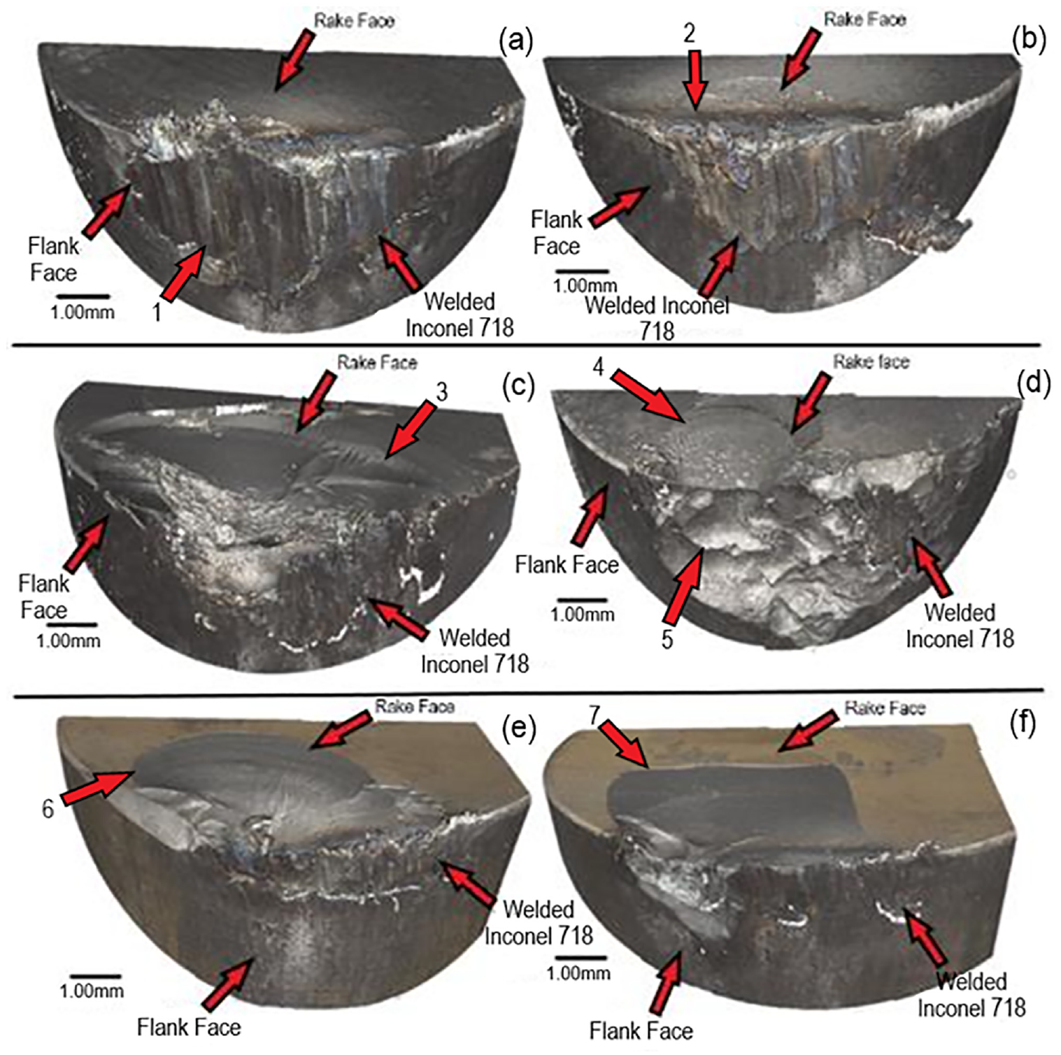
The non-contact 3D profilometer (focus variation type) scan of the three different types of inserts are shown in Figures 8 to 11. Figure 8 highlights the types of primary and secondary wear mechanisms which the uncoated, Coating A and Coating B inserts sustained when facing milling bar sections (1-1-1-4) of Inconel 718 at a cutting speed of 700 m/min. Secondary wear mechanisms such as oxidative wear are visible on the rake face (Region 1 in Figure 8) and abrasive wear is visible on the cutting edge of the rake face for the uncoated and Coating A inserts (Regions 3 and 5 in Figure 8). Flaking and chipping are evident on the rake face for the uncoated and Coating A inserts (Regions 2 and 4 in Figure 8). The flaking and chipping take place due to the change in cutting edge as result of abrasive wear, which causes the contact pressures in the chip/tool interface to increase to a point that it causes the SiAlON ceramic microstructure to shear along the grain boundaries. The shearing effect along the grain boundaries causes a wave like multilayer topography to form as can be seen on the rake face of the Coating B inserts (Regions 6 and 8 in Figure 9). Primary wear mechanisms such as crater wear are visible on the flank face of the Coating B inserts (Regions 6 and 7 in Figure 8). During the machining process, as the three types of inserts sustain more wear on the flank and rake faces and remove more metal, the level of vibrations begin to increase. Once the coatings delaminate and flake off the inserts, a cutting surface with different coating thicknesses on both the rake and flank faces of the Coating A and Coating B inserts is created which contributed to the exacerbation of the insert wear mechanisms.
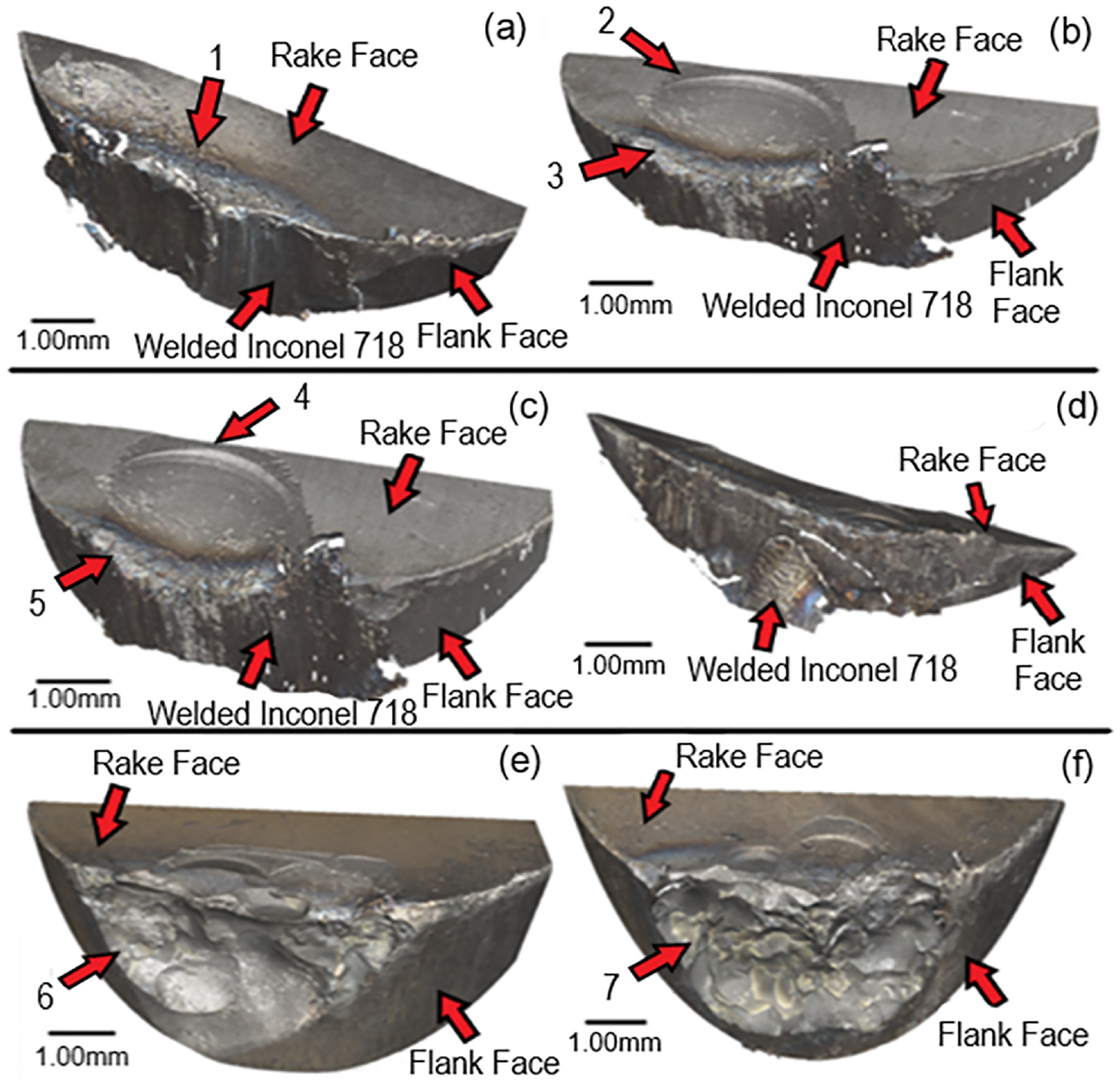
Tests at 700 m/min, 0.1 mm/rev, 1.0 mm (ap), non-contact 3D profilometer (focus variation type) scan: insert-Uncoated-insert-1 & 3 (a and b) the material removed is 135.716 cm3, insert-Coating-A-insert-1 & 3 (c and d) the material removed is 67.858 cm3, insert-Coating-B-insert-2 & 4 (e and f) the material removed is 135.716 cm3.
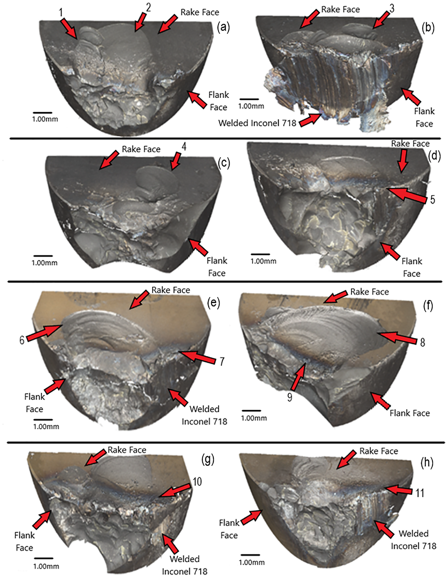
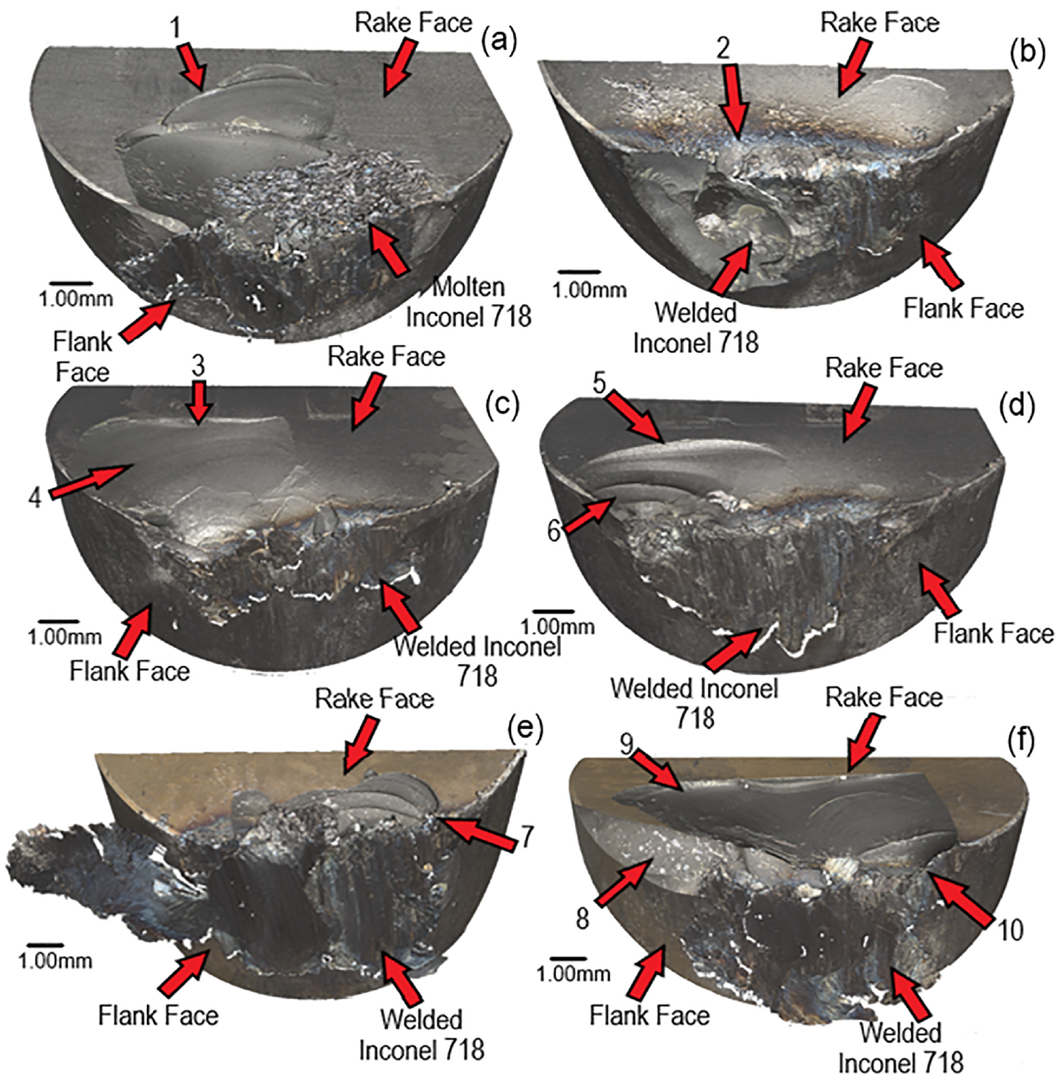
Tests at 800 m/min, 0.1 mm/rev, 1.0 mm (ap), non-contact 3D profilometer (focus variation type) scan: (insert-Uncoated-insert-2 & 3 (a and b) the material removed is 169.645 cm3, insert-Coating-A-insert-2 & 3 (c and d) the material removed is 169.645 cm3, insert-Coating-B-insert-2 & 3 (e and f) the material removed is 135.716 cm3, insert-Coating-B-RP-insert-2 & 3 (g and h) the material removed is 101.787 cm3.
Tests at 900 m/min, 0.1 mm/rev, 1.0 mm (ap), non-contact 3D profilometer (focus-variation type) scan: insert-Uncoated-insert-2 & 4 (a and b) the material removed is 169.645 cm3, insert-Coating-A-insert-2 & 4 (c and d) the material removed is 135.716 cm3, insert-Coating-B-insert-1 & 2 (e and f) the material removed is 67.858 cm3.
Tests at 1000 m/min, 0.1 mm/rev, 1.0 mm (ap), non-contact 3D profilometer (focus-variation type) scan: insert-Uncoated-insert-2 & 3 (a and b) the material removed is 135.716 cm3, insert-Coating-A-insert-1 & 4 (c and d) the material removed is 135.716 cm3, insert-Coating-B-insert-1 & 4 (e and f) the material removed is 67.858 cm3.
Figure 9 highlights the types of wear which the inserts sustained when facing milling bar sections (2-1-2-5) of Inconel 718 at a cutting speed of 800 m/min. Once again flaking and chipping are evident on the rake face for the uncoated and Coating A inserts (Regions 1, 2, 6 and 8 in Figure 9). The level of insert wear is reflected by the volume of metal that has been removed as bar sections (2-1-2-5) were machined by the uncoated and Coating A inserts.
Isolated chipping and flaking were also evident on the rake face for the uncoated and Coating A inserts (Regions 3 and 4 in Figure 9). The isolated chipping and flaking are likely a result of fluctuating tensile and compressive stresses being distributed across the rake face. Oxidative wear is yet again visible on the rake face for all the inserts (Regions 5, 7, 9, 10 and 11 in Figure 9).
As the cutting speed was increase up to 900 and 1000 m/min the type of insert wear mechanisms changed. Figure 10 highlights the types of wear mechanisms which the all the inserts sustained when facing milling bar sections (3-1-3-5) of Inconel 718 at a cutting speed of 900 m/min. Adhesive wear had been apparent throughout the machining tests, but adhesive wear was more prominent at cutting speeds of 900 and 1000 m/min with the uncoated inserts (Region 1 in Figure 10). This increase in adhesive wear is due to an increase in temperature in the chip/tool interface and the localised welding and fusing of the chip onto the surface of the uncoated inserts. Coating A sustained significant amounts of chipping, flaking and crater wear (Regions 3, 4 and 5 in Figure 10) and Coating B inserts had chipping, flaking and crater wear (Regions 6 and 7 in Figure 10). However, the bilayer coating of Coating B failed after machining bar sections (3-1-3-2). This likely due to titanium nitride (TiN) outer layer oxidising as a result of the increased cutting speed and cutting temperature.
The oxidised surface ablates off the surface of the insert causing the uneven sliding surface contact to exacerbate the flank and rake face wear. The uneven surface contact contributes to high fluctuations in the tensile and compressive stresses in the chip/tool interface and shortens the tool life of the Coating B inserts.
Figure 11 highlights the types of wear which all the inserts sustained when facing milling bar sections (4-1-4-4) at a cutting speed of 1000 m/min. The failures that had been evident for Coating B at a cutting speed of 900 m/min were also evident when the inserts were tested at 1000 m/min. Coating B failed after machining bar sections (4-1-4-2), with the TiN outer coating degrading in the same way that had been experiences in the previous test that were completed at 900 m/min. Flaking, chipping Figure 11 shows that all three types of insert suffer from flaking and chipping (Regions 1, 3, 5, 6, 7 and 9 in Figure 11) with tool fracture happening with Coating B (Regions 8 and 10 in Figure 11). What must also be noted is how the Coating A inserts improved in wear resistance, in comparison to the uncoated inserts as the cutting speed was increase in cutting speed up to 1000 m/min.
Tool life curves
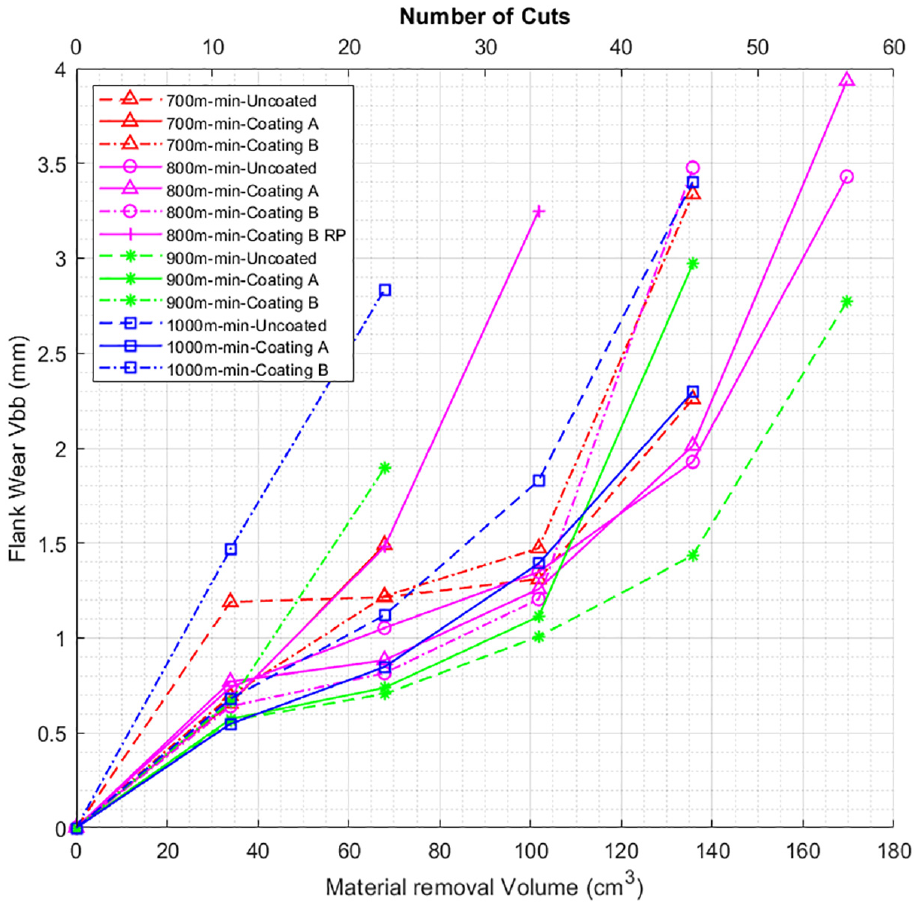
The tool life curve shown in Figure 12 represents the magnitude of flank wear which each of the three different types of inserts experienced when operated at a cutting speed of 700, 800, 900 and 1000 m/min.
700, 800, 900, 1000 m/min facing op 1.1-4.5 Uncoated/Coating A/Coating B/Coating B RP.
The 1.0 mm depth of cut and feed per tooth of 0.1 mm/tooth remained constant throughout the entire machining trial. Over the four sets of cutting speeds, the uncoated CTIS710 milling inserts achieved the best overall wear resistance and resistance to sudden failure. The CVD coated SiAlON ceramic milling inserts have performed well at cutting speeds of 700 and 800 m/min regarding flank wear measurements that were captured from in the earlier sets of test cuts.
When the cutting speed was increased to 900 and 1000 m/min, however, Coating B seemed to suffer from a series of exacerbated wear mechanisms ranging from thermomechanical wear, oxidation, abrasive wear, crater and notch wear, which ultimately led to poor tool life and high tool wear rates. Coating A appeared to perform better when the cutting speed was increased. The increase in cutting performance is likely due to Coating A being removed from the surface of the SiAlON substrate rather easy during the machining of the sections 1 and 2. Once Coating A has subsequently been removed from the surface of the SiAlON, it leaves a clean fresh cutting surface which can be used in the machining of the latter sections.
Conclusions
The following conclusions can be drawn from this study:
The uncoated SiAlON inserts achieved more consistent cutting performance in terms of material removed from the workpiece for a given magnitude of insert flank wear.
Coating B generated less cutting force when machining initial sections when compared to A and the uncoated inserts.
The degradation of Coating B is due to the presence of oxidised titanium nitride, exacerbating flank and rake face wear.
Titanium nitride in CVD coatings should not be used for protecting SiAlON ceramic milling inserts due to their poor thermal performance.
Heating and cooling cycles due to interrupted cuts exacerbated the wear mechanisms encountered by the coated inserts.
Footnotes
Declaration of conflicting interests
The author(s) declared no potential conflicts of interest with respect to the research, authorship, and/or publication of this article.
Funding
The author(s) disclosed receipt of the following financial support for the research, authorship, and/or publication of this article: The authors would like to thank the Engineering and Physical Sciences Research Council (UK) (EP/L016257/1) and the University of Sheffield’s Advanced Manufacturing Research Centre (AMRC) for the kind sponsorship of this work. The authors would also like to thank Ceratizit Ltd UK for supplying the ceramic inserts, insert holders and spindles for this research project.