
Abstract
During machining processes, the temperature of the workpiece may vary due to different factors. One of such factors is the heat generated due to tool/workpiece friction. Temperature may also vary due to environmental conditions. These temperature variations can affect the dimensional accuracy of the manufactured workpiece. It is known that the expansion of a part is related to a change in its average temperature, which is influenced more by the internal, core temperature than the surface temperature. The surface temperature of the part being manufactured can vary significantly from the core temperature, especially during dry cutting processes. Therefore, to effectively control or compensate for the effects of temperature variation as it relates to material expansion, there is a need to measure the core temperature of the workpiece accurately. In this article, a novel ultrasonic phase-shift method for temperature measurement is used to measure the core temperature of a workpiece on a computer numerical control machine (CNC). The results show that the phase-shift ultrasonic thermometry method measures steel workpiece temperature during subtractive manufacturing processes with deviations of less than ±1°C when compared to the reference PT100 readings. This novel temperature measurement method can be used in different manufacturing processes as part of a temperature control or thermal error compensation system.
Keywords
Introduction
The dimensional accuracy and surface integrity of manufactured workpieces are directly affected by temperature variations during manufacturing and these two specifications are indicators of the conformance of the manufactured workpieces to the design intent.1–4 Therefore, there is a need to have a system in place for temperature control and/or to compensate for the effect of temperature variation.
Many manufacturing environments can be very harsh and in the case of subtractive production processes, heat is generated and metal swarf and cutting oil are often present on the workpiece being machined. Traditional methods of temperature measurement during manufacturing such as thermocouple, resistance temperature detectors, and infrared thermometry all measure the surface temperature of an object. However, the surface temperature is not always indicative of the material’s core temperature.5,6 Rai et al. showed that the temperature difference between the cut and the uncut volume of a workpiece can reach 54.2°C during a machining operation. 7 This shows that the temperature at the surface does not truly represent the entire workpiece volume, especially in large workpieces and, in any case, surface measurement is often impractical for the workpiece due to the changing surface condition during manufacturing. In this study, the core temperature is defined as the average internal temperature of the workpiece rather than a spot temperature on the surface of the workpiece.
The velocity of sound in any medium depends on the physical properties of that medium, of which temperature is a crucial part. 8 This relationship has been used in different types of applications such as flaw detection (e.g., cracks and inhomogeneity) in non-destructive testing, thickness gauging, and imaging for medical purposes. The spectrum of sound wave mostly used for these purposes is the ultrasound – sound waves above 20 kHz. In ultrasound applications, the sound wave is generated using an ultrasonic transducer which is excited by an electronic pulser. The wave is transmitted through the medium of interest with the aid of a couplant. 9 The return wave is then captured with a receiver. With the knowledge of the time-of-flight and the distance of travel, the ultrasonic velocity can be calculated.
Two of the main methods of time-of-flight ultrasonic measurements are the pulse-echo and the phase-shift method. The pulse-echo method uses discrete ultrasonic pulses for time-of-flight measurement, while the phase-shift method uses the difference in the phase of steady-state frequency ultrasonic waves between transmitted and received signals for ultrasonic time of travel measurement. 10 The phase-shift method was used by Abdelmejeed et al. to measure the temperature of a silicon wafer using a voltage control oscillator. 11 The thickness of the sample investigated (0.65 mm) is small when compared to many machining applications. The attenuation of the signal in a larger workpiece means that this signal source would not be appropriate. Previous research has shown that by using an ultrasonic phase-shift method, the core temperature of a 100 mm steel part can be measured with a resolution of 0.1°C in an ideal environment. 12 However, ultrasonic phase-shift thermometry during a machining process, or indeed in a manufacturing environment, has not been reported in literature. It is expected that the additional uncertainties introduced by the vibration and the presence of swarf during machining may have an impact on the accuracy of the temperature measurement method.
The motivation for the present study is the need to create a temperature measurement method that gives a measurement value that is representative of the entire workpiece volume, rather than a spot temperature at the surface of the workpiece. This is because a spot temperature value, especially close the tool-workpiece interface is usually higher than the average workpiece temperature. 7 If such measurement values were to be used for temperature control and/or thermal error compensation, the accuracy and reproducibility of the finished product can be improved. Hence, a more representative temperature value will increase the accuracy of the machined part, leading to less scrappage and improved time of manufacturing of parts.
In this article, the ultrasonic thermometry method was investigated for use during machining. This was achieved by building up experiments to investigate the effects that important factors have on the suitability of the ultrasonic thermometry method to meet the required specification and these factors are described in the “In-process ultrasonic thermometry” section.
Workpiece temperature distribution, control, and thermal error compensation
During machining, much of the energy expended on metal removal is converted into heat. The heat is initially imparted into the tool, workpiece, and the swarf/cutting chips, 13 though eventually it can also be transmitted into the fixture and machine tool structure. This article concentrates only on the heat transmitted into the workpiece. Due to the material expansion caused by a change in workpiece temperature, the machining process can produce dimensional and geometrical errors in parts that are then significantly out of tolerance. 7 Different methods have been used to measure both tool and workpiece temperature. The methods include the thermocouple,14,15 infrared thermometry, 16 thermographic phosphor sensor, 17 and resistance temperature detectors.18,19 In each case, this only provides information about the surface temperature, unless sensors are embedded in the workpiece, which is often impossible, due to the invasive nature of this approach. A knowledge of the average temperature inside the workpiece would aid the control of the temperature and/or compensation for the effects of temperature change.
Cutting fluids have long been used for their basic actions of cooling and lubrication and are therefore considered a temperature control method.20,21 In practice, the cutting fluid is only sometimes chilled and other times drawn from a tank held at ambient temperature, but iteratively warmed as it is used. Therefore, the temperature control of the workpiece retains high levels of uncertainty. Additionally, the significant impact of cutting fluids on the environment, on the health of the operator and their high contribution to the manufacturing cost, which can be as high as 16%, have resulted in alternative temperature control methods being favored for sustainable manufacturing.22–25 Other methods such as the use of self-lubricated textured tool, 25 minimum quantity lubrication (MQL), and other green cutting technologies such as mist cooling, compressed air cooling, liquid nitrogen cooling, and dry cutting have been described in literature. 26 A temperature control model described by Benabid et al. 27 uses a short period of reduction in cutting speed for cooling the mill. By using a thermocouple, they were able to monitor the temperature of the tool when it leaves the surface of the workpiece. However, their approach does not apply to this study as the temperature value in their study does not represent the volume of the workpiece.
None of the temperature measurement methods reviewed above can truly give a temperature reading that is representative of the entire material volume. Ultrasonic thermometry is based upon ultrasonic wave velocity measurement over the entire wave transit path, hence it gives an average temperature value that is representative of the entire path.
Apart from temperature control of workpiece, compensation of the thermally induced dimensional distortion can also be carried out during the machining process. Modern machining centers allow for numerical compensation to be carried out for the effects of temperature change, such as thermal expansion. 28 By feeding the temperature value to a compensation system with an established model, the positioning command can be modified to compensate for the material expansion caused by the temperature change in both the machine and the workpiece. Most thermal compensations deal only with the thermally-induced deformation of the machine itself, but by being able to measure the average core temperature of a workpiece it becomes possible to compensate for the thermal errors of the part as well. It is also known that the increase in workpiece temperature can accelerate tool wear, 29 therefore, core temperature measurement has the potential of aiding temperature control and consequently prolonging tool life and optimizing tool performance. 30
Materials and methods
The phase-shift method of ultrasonic measurement uses the difference in the phases of steady-state frequency ultrasonic waves between transmitted and received signals for ultrasonic velocity measurement. 10 For an ultrasonic wave of a known frequency travelling through a known distance, the phase difference between the transmitted and the received signals can be used to obtain the ultrasonic velocity through the medium of propagation. The equation relating the phase-shift to the ultrasonic velocity is given as:

where L is the distance of travel of the ultrasonic wave, n is the integer number of wave periods, φ is the phase-shift between the transmitted and the received signals, c is the ultrasonic velocity in the medium, and f is the frequency of the signals. 31
Temperature change affects both the ultrasonic velocity and the material dimension (thermal expansion). However, a previous study has shown that the effect of change in ultrasonic velocity on the time-of-flight is significantly more than that of the material expansion. 32 Hence, in this study, the detected change in temperature will be based upon the change in ultrasonic velocity. The temperature–ultrasonic velocity relationship derived by experiments is given by Ihara and Takahashi 33 as:

where c(T) is the temperature dependent ultrasonic velocity and T is the temperature.
A major advantage of using the phase-shift method is that it reduces the type of attenuation caused by short-burst transmission. 31 Results of simulations and laboratory experiments in previous research showed that the phase-shift method resolves 0.1°C change in temperature with relatively less expensive setup when compared with the pulse-echo method.12,34
For phase-shift ultrasonic measurements, the dual element transceiver or simply “duals” can be used for a seamless send-receive operation of the ultrasonic signal. The transducer contains two elements with each being independent of the other. The main advantage of the dual element transducer is that because one element serves as the transmitter while the other acts as the receiver, only one transducer is needed for the phase-shift ultrasonic method where the signal is continuously being generated. The two elements in duals are separated by an acoustic barrier and are both slightly angled towards each other so that the transmitted and received waves have a “V” shaped path.
Ultrasonic couplants are used to aid the transmission of ultrasonic wave from the transducer to the medium of ultrasonic wave propagation. The use of a couplant is necessary if the medium of propagation is solid as this helps to remove any air from the surface of both the transducer and the solid material. Air causes significant loss in transmission due to the low acoustic impedance of air compared to the transducer and the solid medium. 35 The acoustic impedance of air is about five orders of magnitude lower than that of the ultrasonic transducer and steel. 36 Therefore, using ultrasonic couplants with high impedance significantly improves the transmission of ultrasonic signals. 37
The acoustic impedance of air and some other media are given in Table 1.38–40
Acoustic impedances of some common media.
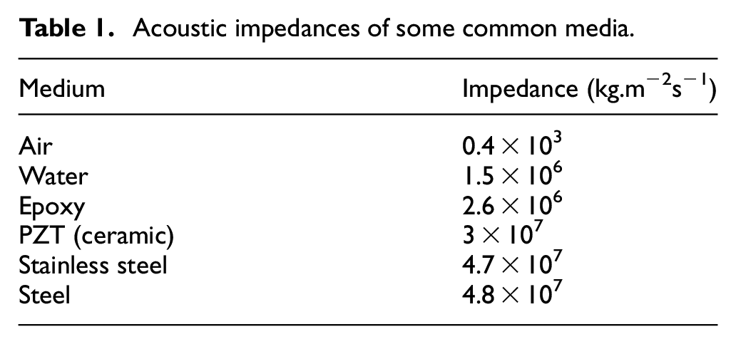
Epoxy resin is an adhesive couplant for use with a metallic medium of propagation. 41 Epoxy resins are stable and they have relatively high acoustic impedance when compared with other couplants and it has also been shown that epoxy bonds can be broken off when they are no longer needed. 42 Epoxy was chosen because its strength, good transmission, and reusability are desirable for the present task.
In-process ultrasonic thermometry
Three types of in-process experiments were planned to validate the temperature measurement system at different stages, namely: static tests, spindle running tests, and dry-cutting tests. The purpose of the static tests is to detect any possible interference of the machine tool’s electrical and drive systems with the ultrasonic thermometry setup that could impact on the accuracy of the system. The spindle running tests were designed to observe any effect of the attendant vibration on the accuracy of the results. Finally, the cutting trials were designed to evaluate the performance of the setup during a machining process.
The devices chosen for this experiment have been used in previous laboratory experiments to establish the possibility of resolving a 0.1°C change in material temperature. 34 A Spectrum M2i.6022-exp arbitrary waveform generator (Spectrum Instrumentation, Ahrensfelder, Grosshansdorf, Germany) was used for continuous waveform generation. It was chosen because of its availability, performance, and PCIe form factor enabling high speed PC data logging. It has a maximum clock speed of 62.5 MS/s as specified in the data sheet. 43 NDT Systems DVF014 ultrasonic transducer (NDT Systems Inc, Huntington Beach, CA, USA) was chosen. The 1 MHz dual element transducer has a center frequency of 1.038 MHz and a bandwidth of 1.465 MHz at −6 dB and 1.831 MHz at −12 dB. The echo-signal was amplified using a Texas Instrument THS3202 high speed amplifier (Texas Instrument, Dallas, TX, USA). The phase-shift between the sent and amplified echo signal was measured using Analog Devices AD8302 phase detection board (Analog Devices, Norwood, MA, USA). The phase detection board outputs phase difference as voltage values. The voltage output was filtered using a 3.4 Hz low-pass filter; however, a cutoff frequency of similar value will give satisfactory results. An NI-9239 analogue input card (National Instruments, Austin, TX, USA) was used for data acquisition which was then stored using NI LabVIEW. A PT100 temperature detector inserted into a hole drilled into the workpiece was used for reference temperature measurement.
A steel (EN24T) workpiece was cut to a nominal length of 120 mm, width of 120 mm, and height of 30 mm. This was done to accommodate a PT100 insert for reference temperature measurement. A hole of nominal diameter 6.2 mm and depth of 115 mm was drilled at the center of the 30 mm face of the workpiece to hold the 115 mm long PT100 detector. The PT100 detector used in this study was calibrated using a TCS 140 liquid bath calibrator. The measurement values from the calibrated PT100, which represented the average temperature across the length of the workpiece, was used as the reference core temperature values, this is comparable to the ultrasonic readings which are also representative of the average internal temperature. The PT100 detector was inserted and glued using a hot glue gun and this was done to prevent sensor movement during cutting operations. The ultrasonic transducer was coupled using previously discussed epoxy at approx. 15 mm (clearance for glue and epoxy) from the center of the drilled hole as shown in Figure 1.
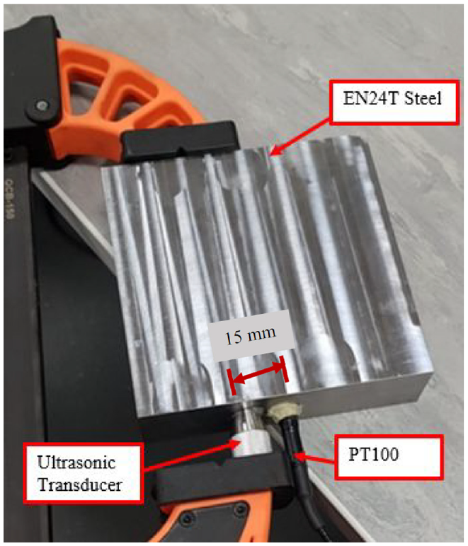
Transducer and PT100 spacing on workpiece.
The temperature of the EN24T steel workpiece was measured in a CNC workshop and this was done to observe the stability of the setup in the CNC workshop. The setup used is shown in Figure 2.
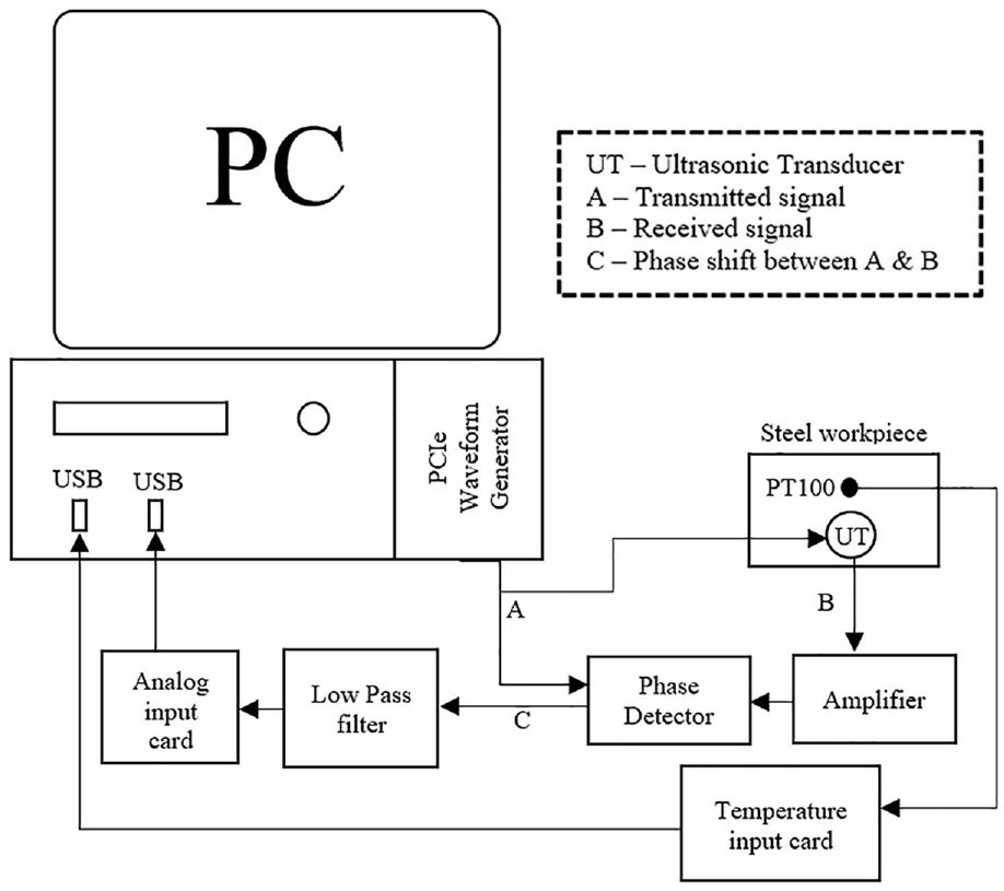
Ultrasonic thermometry setup.
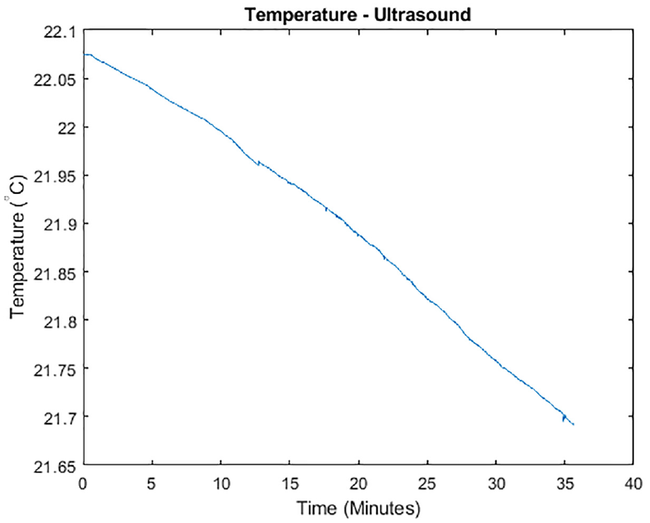
The recorded temperature readings captured the change in temperature due to the drop in the workpiece temperature from 22.07°C to 21.69°C over a period of approximately 35 min. The PT100 and ultrasound readings are shown in Figures 3 and 4, respectively.
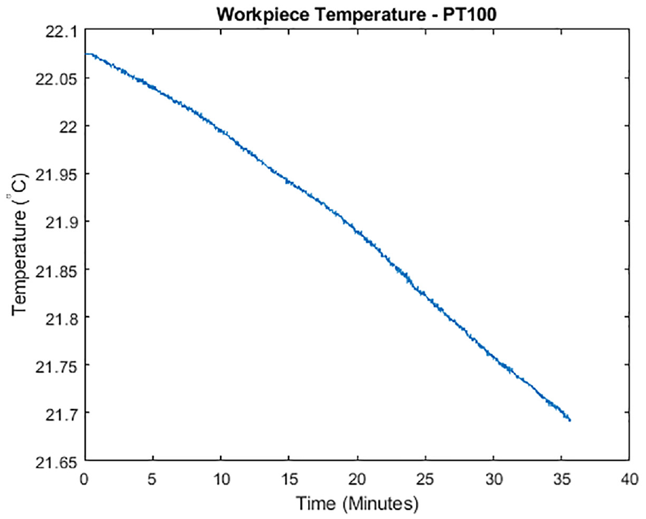
PT100 Workpiece temperature readings.
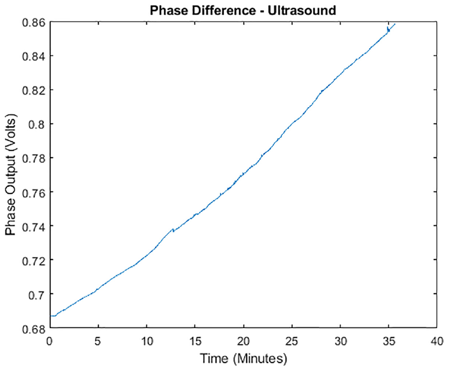
Ultrasonic phase difference readings.
Using the linear interpolation function, the phase output voltage values were converted to temperature values. The linear interpolation function provides approximated values which can be directly compared with the PT100 values for error estimation and further analysis. The linear interpolation function will also be used for subsequent results. The interpolated result is given in Figure 5.
Interpolated ultrasonic temperature results.
The deviations of the ultrasonic readings from PT100 values were calculated and the temperature difference plot is given in Figure 6.
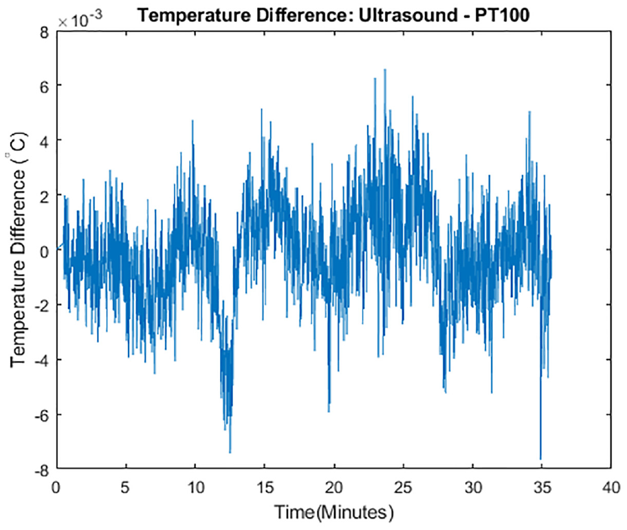
Deviation of ultrasonic readings from PT100 readings.
The temperature difference values are within ±0.008°C which are well within allowable temperature variation in precision manufacturing.
A three-axis Cincinnati CNC milling machine was used for the in-process tests. The CNC and test equipment are shown Figure 7.
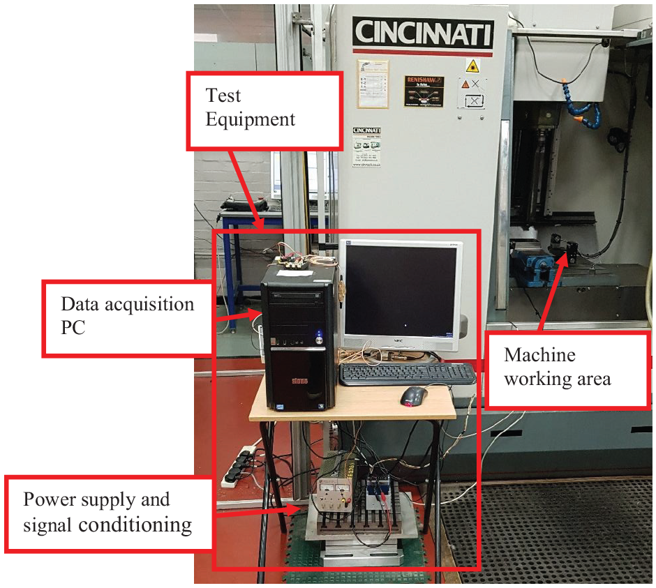
CNC and data acquisition setup for ultrasonic thermometry.
To ensure steady positioning of the transducer during machining and minimize pressure variation on the ultrasonic couplant due to machining vibration, an improvised mechanical clamp was used to fix the ultrasonic transducer in place before the epoxy bond has set to prevent the clamping from breaking the bond.
The following experiments were planned to systematically increase the number of uncertainties introduced to the measurement and observe the agreement of the ultrasonic thermometry results with that of the PT100.
The first experiment was designed to take the measurement while the CNC is switched on with drives on but without the spindle running. This experiment will help to determine if there is any electromagnetic interference with the ultrasonic measurement from for example, drive motors, pumps, and other high-power electrical systems often found on CNC machine tools. After an initial observation, the experiment was carried out over a prolonged period of approximately 13 h. This was done to observe the stability of the measurement result over time.
The second experiment was carried out with the CNC spindle running. The aim of this experiment is to observe the effect of the attendant vibration on the measurement results. This experiment was carried out for both 1000 rpm and 5000 rpm. These values were chosen to independently observe the effects of high and low speed revolution on the ultrasonic measurement. Thereafter, the cutting trial was carried out.
Static test (CNC switched on)
The initial data was captured for approximately 20 min. The result of this test is given in Figure 8.
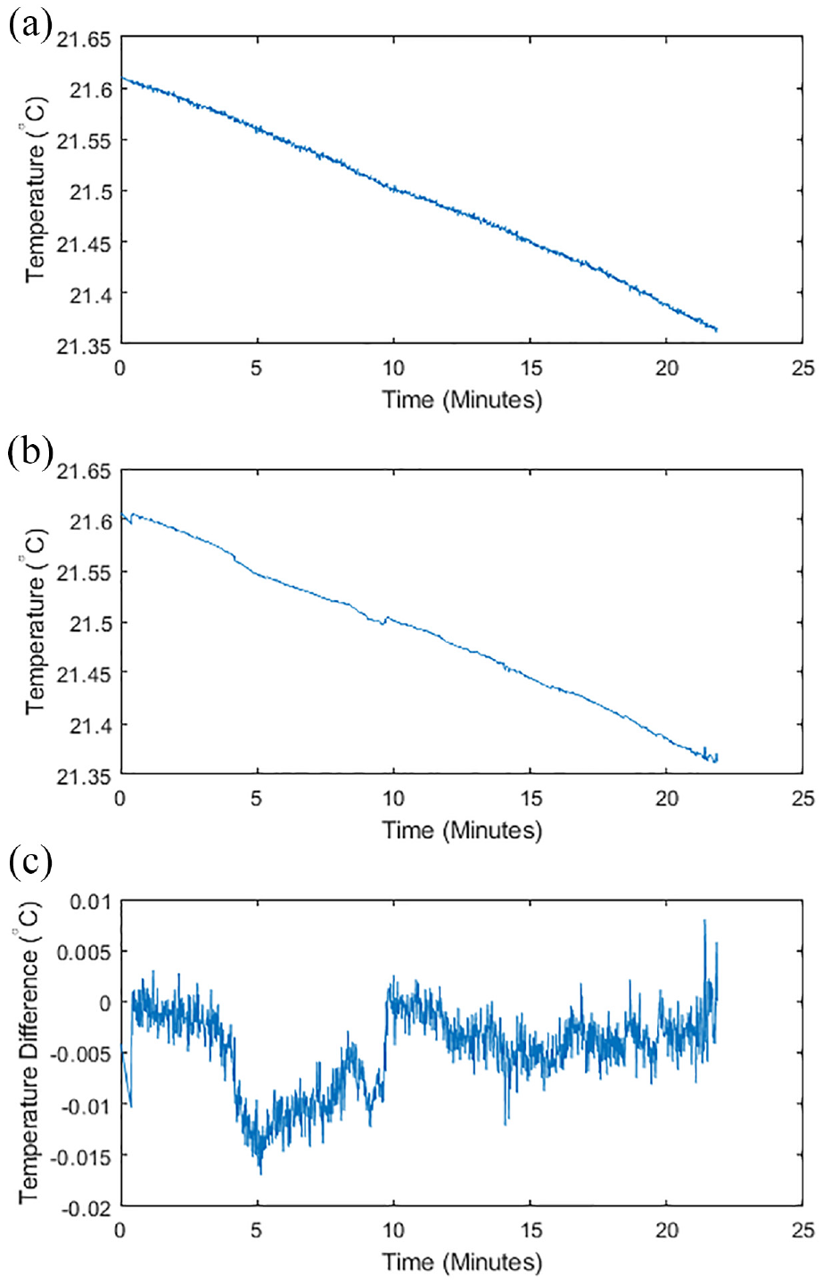
PT100 and ultrasonic thermometry results of static test: (a) PT100 (static test 1), (b) ultrasound (static test 1), and (c) difference (ultrasound-PT100).
The results show that the ultrasonic thermometry readings agree with the reference PT100 with differences within range of −0.017°C to +0.0081°C and a standard deviation of 0.0039°C. These difference values are still within acceptable values for precision manufacturing; however, it is necessary to analyze both the PT100 and ultrasonic results for the observed variabilities and their individual contributions to the deviations. For this, a high pass filter was considered. The high pass filter will be used to separate the slow changing temperature values from the high frequency noise. To select an appropriate cutoff frequency for the filter, a target resolution of 0.1°C was taken into consideration. The chosen cutoff frequency should not cause a delay in response such that possible compensation for thermal expansion will lag more than the target resolution. For this, the typical temperature rise time during cutting was observed. The temperature of a typical part used in this study will rise by 0.1°C in 0.36 s. This means that the cut-off frequency should not be lower than 2.8 Hz to preserve the target resolution. Therefore, a 3 Hz cutoff frequency was chosen. The high pass filter was applied to both PT100 and ultrasonic data in MATLAB and the results are shown in Figure 9.
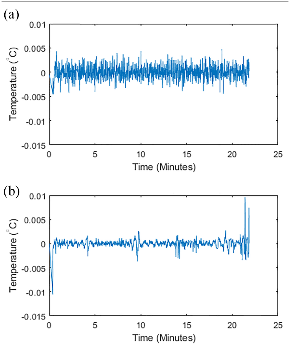
Residuals of PT100 and ultrasonic thermometry for static test: (a) PT100 (residuals) and (b) ultrasound (residuals).
The results of the high pass filtering show that the standard deviation of the PT100 residual values is 0.0014°C and the standard deviation of the ultrasound residual values is 0.00091°C. The range of the residuals is −0.0045°C to +0.0047°C for PT100 and −0.0106°C to +0.0096°C for the ultrasound readings. Although the range of the ultrasound residuals is higher than the PT100, the plots show that this is because of the spike at the beginning and the end of the data which could be due to movements while starting and stopping the experiments. These cannot reasonably be temperature readings due to thermal inertia and there is a need to filter the spikes out from the data. The standard deviation values also show that there is more variability in the PT100 data than in the ultrasound data. This could be due to the circuitry of the sensor. To remove the noise in both PT100 and ultrasound data, a lowpass filter was applied, using the same 3 Hz cutoff frequency.
After filtering, the range of the temperature difference values reduced to −0.0143°C to 0.00082°C from −0.017°C to +0.0081°C and the standard deviation reduced to 0.0036°C from 0.0039°C.
The same test was repeated for an extended period (approximately 13 h). This was performed to observe how stable the readings are over an extended period that could represent a very long machining cycle. The result of this test is shown in Figure 10.
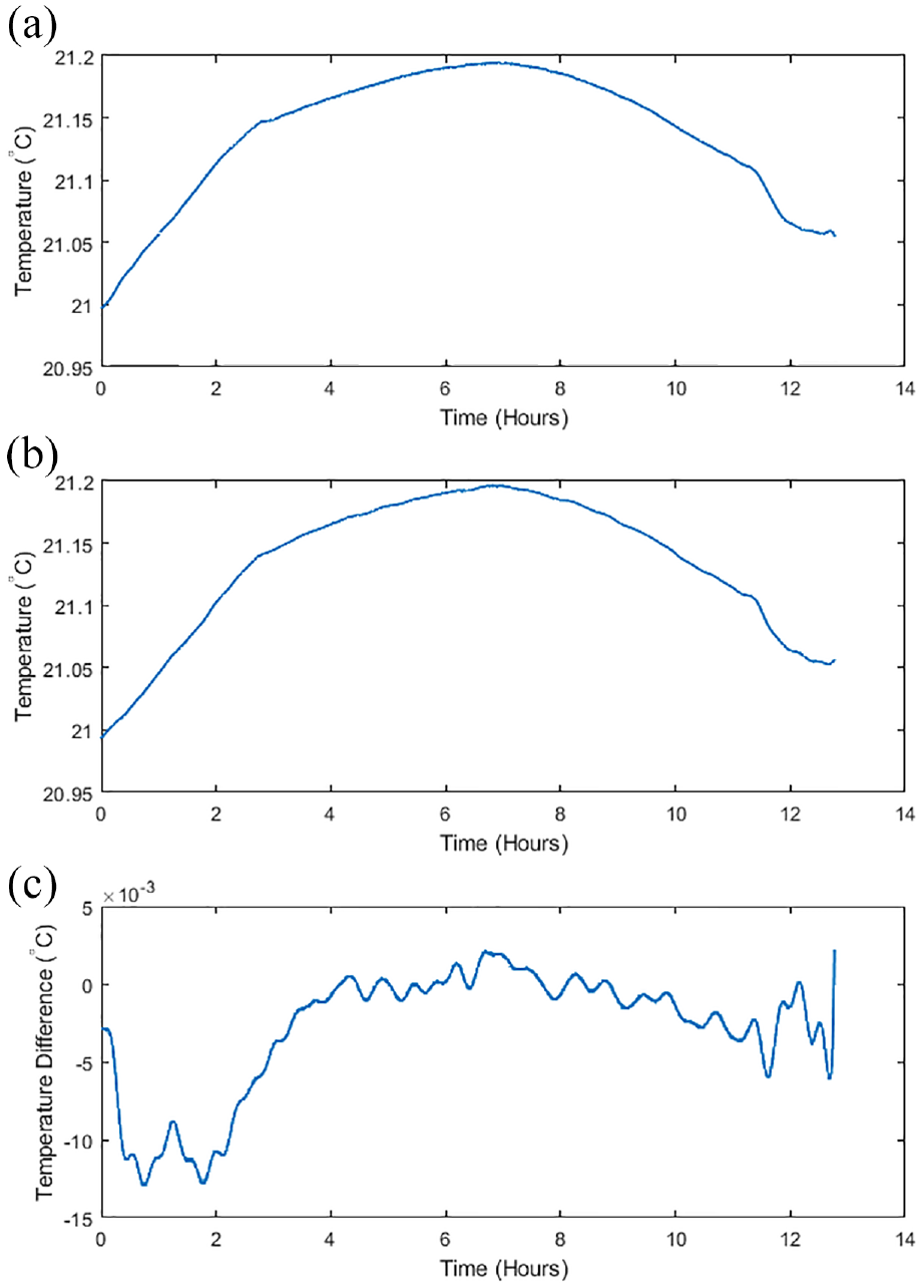
Results of the extended static test: (a) PT100 (extended static test), (b) ultrasound (extended static test),(c) difference (ultrasound – PT100).
Before filtering, the temperature difference values over the 13 h were within the range of −0.0179°C to +0.0089°C with standard deviation of 0.0043°C. After filtering, the temperature difference range reduced to −0.0130°C to +0.0022°C with standard deviation of 0.0040°C. This result shows that the ultrasonic thermometry setup is stable over time. Furthermore, none of the static test results show any observable interference with the results of the ultrasonic thermometry.
Spindle running tests
The aim of the spindle running tests is to observe the effects of the attendant vibration and possibly increased electromagnetic interference on the accuracy of the ultrasonic readings. This test was planned to have two parts, a relatively low speed test of 1000 rpm and another test with higher speed of 5000 rpm which is the maximum speed for the machine. It is expected that the improvised clamping and the epoxy resin used for coupling the ultrasonic transducer to the steel workpiece will reduce the effects of the vibration on the accuracy of the ultrasonic thermometry readings both during the spindle running tests and during actual cutting.
The results show that there was no reduction in the accuracy of the measurement. This test is an example of results that may be obtained due to running of the spindle, however further tests are required to fully characterize the results obtainable with the measurement setup at different frequencies and configurations. Before filtering, the error values for the 1000 rpm test were in the range of −0.0139°C to +0.0080°C with standard deviation of 0.0042°C and the temperature difference range for the 5000 rpm test was −0.0105°C to +0.0194°C with standard deviation of 0.0047°C. After filtering, the temperature difference range for the 1000 rpm test reduced to −0.0107°C to +0.0055°C with standard deviation of 0.0038°C and the temperature difference range for the 5000 rpm test reduced to −0.0052°C to +0.0126°C with standard deviation of 0.0041°C. The results of the 1000 rpm and the 5000 rpm tests are shown in Figures 11 and 12, respectively.
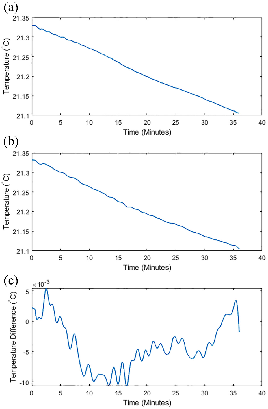
Results for spindle running at 1000 rpm: (a) PT100 (spindle running (1000 rpm)), (b) ultrasound (spindle running (1000 rpm)), and (c) difference (ultrasound – PT100)).
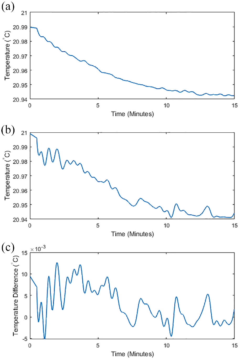
Results for spindle running at 5000 rpm: (a) PT100 (spindle running (5000 rpm)), (b) ultrasound (spindle running (5000 rpm)), and (c) difference (ultrasound – PT100)).
Dry cutting trials
Cutting fluids are used to reduce the friction between the workpiece and cutting tool and reduce the temperature during cutting operations. 44 However, cutting fluids have a negative impact on the operator’s health, the environment, and on the cost of machining. 24 Therefore, alternative machining methods such as dry cutting are now being explored for more sustainable manufacturing.24,25,44 This, however, means that the workpiece temperature change can be higher during dry cutting when compared with processes where cutting fluid is applied. Compensating for the effect of this change in temperature by using the surface temperature can lead to a reduction in accuracy of the machined part and this is because a spot temperature may not be truly representative of the workpiece volume. Therefore, ultrasonic thermometry during dry cutting has the potential of giving more accurate temperature measurement values while facilitating the advancement towards a more sustainable manufacturing process. In this study, the ultrasonic thermometry experiment was used during dry cutting.
Using the same setup as previously described for the non-cutting CNC tests, a CNC cutting trial was set up using a 22 mm Indexable Carbide tipped 3 flute end mill. The cutting routine was in three passes with axial engagement of 1 mm, radial engagement of 15 mm, feed rate of 750 mm/min, and spindle speed of 3500 rpm. These values were chosen to generate sufficient heat to provide a reasonable range of temperature measurement. The cutting direction was chosen to be perpendicular to the ultrasonic transducer and PT100 sensor to avoid lateral temperature gradient. The direction of cut is shown in Figure 13.
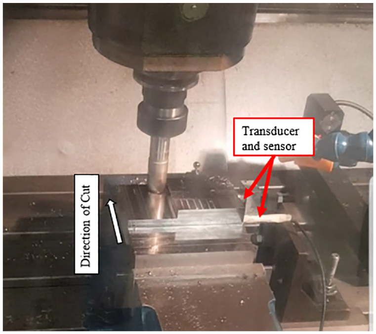
Direction of cut perpendicular to the transducers.
Three cutting trials were done and the results are given in Figure 14.
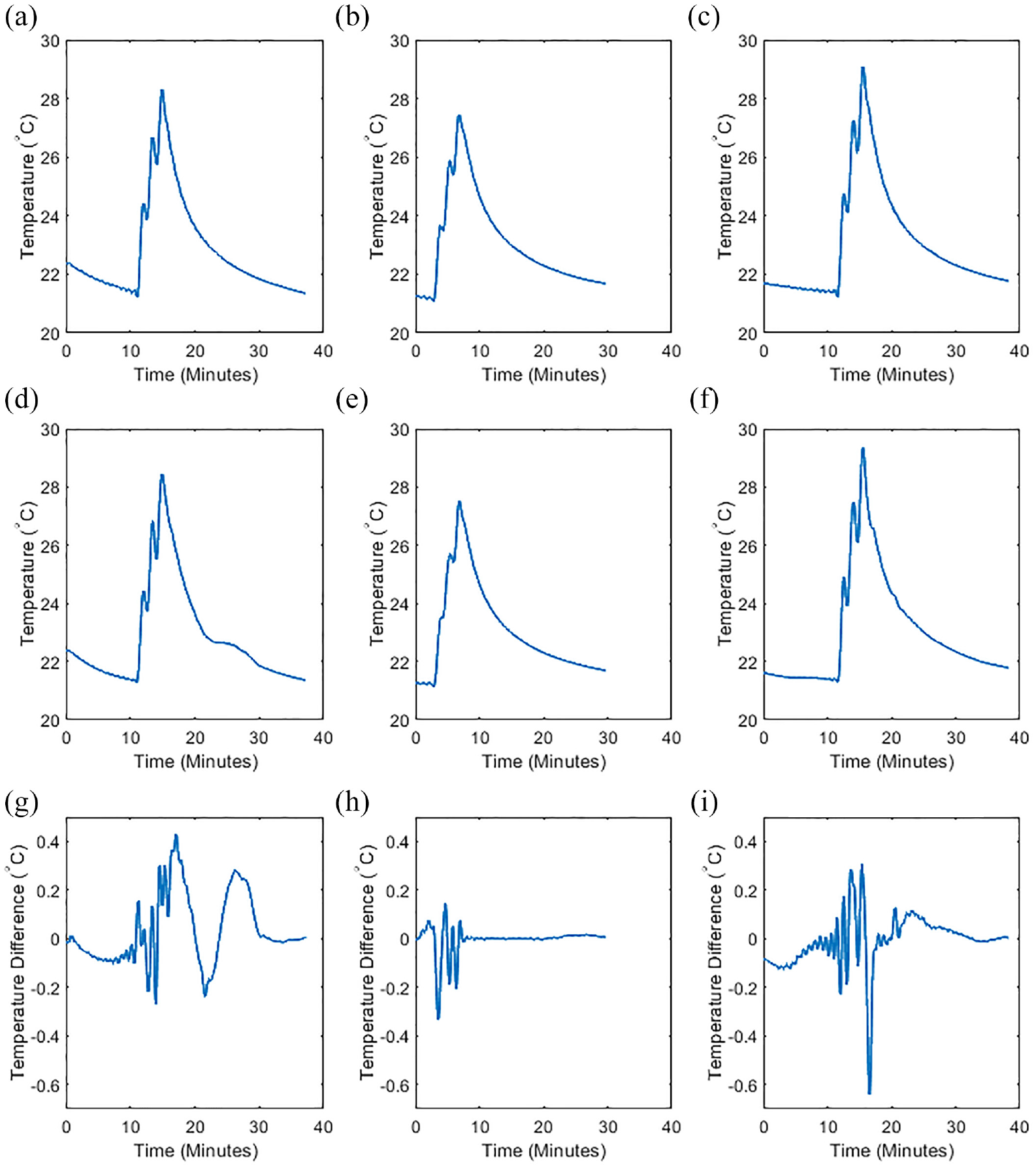
Results of dry cutting trials: (a) PT100 (trial 1), (b) PT100 (trial 2), (c) PT100 (trial 3), (d) ultrasound (trial 1),(e) ultrasound (trial 2), (f) ultrasound (trial 3), (g) difference (trial 1), (h) difference (trial 2), and (i) difference (trial 3).
The temperature difference range and standard deviation for the trials are given in Table 2.
Dry cutting trial temperature difference and standard deviation.
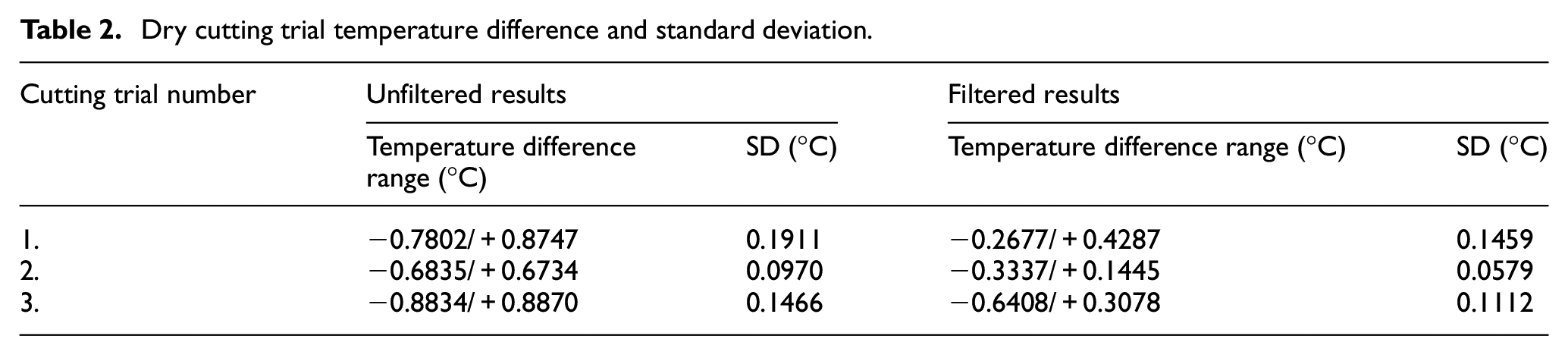
The temperature difference range and the standard deviation are presented in Table 2. The temperature rise within the workpiece during the cutting trials is less than 8°C. The results show that the differences between the ultrasonic thermometry and the PT100 readings are within ±0.9°C before filtering and ±0.7°C after filtering with standard deviation of less than 0.15°C. Also, Figure 14 (G, H, and I) shows that the error values are higher during the moment of impact during the actual cutting process. However, using these temperature values for compensation will still significantly increase the accuracy of the manufactured part as further explained in the next section. The measurement error can be reduced by carrying out the measurement during a short dwell. Further work is needed to understand where this measurement error effect arises, but since the times when the machine is cutting are well-defined, it would be possible in a practical system to synchronize temperature sampling with non-cutting times.
Results and discussion
Using the phase-shift ultrasonic thermometry method, the core temperature of a steel workpiece was measured in cutting and non-cutting conditions. The result of the static test, which was carried out over an extended period of approximately 13 h, shows that the standard deviation of the difference between the PT100 and ultrasonic readings is 0.0040°C. This shows that the ultrasonic thermometry system is stable over time. Also, there was no detectable interference of the machine subsystems with the ultrasonic system on this machine. For the spindle running tests, the temperature difference between the ultrasonic reading and the reference remained within ±0.01°C and this shows that the effect of non-cutting vibration on the setup is minimal. For the cutting trials, the temperature difference values for all the trials fall within ±0.9°C before filtering and ±0.6 after filtering. During the cutting process, the workpiece temperature changed by 6°C, this value represents the temperature rise in the bulk of the uncut volume of the workpiece. Without compensation, this will result in part error of 8.9 µm (Assuming CTE of 12.3 µm/m°C and workpiece length of 120 mm) and in high precision manufacturing, this part will be out of tolerance. If the highest deviation of 0.6°C from the in-process measurement was used for compensation, the error will reduce to 0.9 µm. This shows that the method can reduce dimensional error by a factor of 10 in the given example.
The effects of 6°C and 0.6°C temperature change on some other commonly machined materials are given in Table 3. 45
Effect of temperature change on different materials.
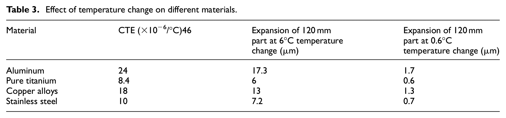
In precision manufacturing, workpieces often need to be manufactured with dimensional error of less than 5 µm. For all the materials in Table 3, applying compensation and/or control to within 0.6°C based on the core temperature measurement will aid the machining of the workpiece within tolerance. The temperature measurement values obtained using the novel method presented in this paper can be used as data inputs for existing or new temperature compensation and control models.
From the cutting trials, the results show that the maximum deviation of the ultrasonic readings from the PT100 readings occurs at the cutting stage, and this is the upward rising slope in the cutting trial plots. In cases where measurement can be carried out during short dwells, the accuracy of the obtained results will be higher than those obtained during the actual cutting process.
Conclusion and future work
The ultrasonic thermometry method presented is a novel method for measuring core temperature of workpieces during manufacturing. The temperature values obtained using the ultrasonic phase-shift method is an average value representing the entire workpiece volume. This gives a more accurate representation of the workpiece when compared with the temperature of a single spot on the surface of the workpiece. The non-cutting experiments and cutting trials show high accuracy when the ultrasonic readings are compared with the PT100 readings. This is crucial for high precision manufacturing processes where the temperature values can be used for compensation during machining for high accuracy. The results show that the method, if used for compensation can reduce part error by up to 8.9 µm for a part of 120 mm length under the conditions of the test. Using this method, temperature control and/or compensation can be more accurately used during different manufacturing processes. To do this, an appropriate thermal error compensation model can be used. This could be an existing model or a new one created for use with the core temperature measurement method which should be followed by experimentation to determine the accuracy of the used thermal error compensation model with the temperature measurement method.
In this study, a simple rectangular-section workpiece was used. Future studies can consider more complex geometries as well as different transducer coupling mechanisms. Future studies can also investigate the use of the ultrasonic method for different materials. Furthermore, work to develop a liquid-protected sensor would allow investigation of workpieces under wet-cutting conditions, where thermal effects on the workpiece can also be found.
Footnotes
Declaration of conflicting interests
The author(s) declared no potential conflicts of interest with respect to the research, authorship, and/or publication of this article.
Funding
The author(s) disclosed receipt of the following financial support for the research, authorship, and/or publication of this article: The authors gratefully acknowledge the UK’s Engineering and Physical Sciences Research Council (EPSRC) funding of the Future Metrology Hub (Grant Ref: EP/P006930/1).