
Abstract
Aside from their remarkable lightness, high strength and corrosion resistance, aluminium alloys have dominated aircraft manufacturing for decades. The combination of aluminium alloys 2024 and 7150 is widely used in the fabrication of airframe structures. Numerous holes must be drilled through the materials in order for them to be connected. Due to structure size and use of mobile drilling machines, lubricant oil is released during the drilling operation and either becomes airborne or accumulates on the floor. The primary motivation for dry drilling development is to avoid this oil discharge. A significant disadvantage of the drilling process for aluminium alloys is the workpiece’s proclivity to stick to the cutting tool, especially when temperatures are high. This research investigated the selection of cutting conditions that enable dry drilling of stack aluminium panels. The selection of cutting parameters for experiment use was made based on the assessment of literature pertaining to drilling with carbide cutting tools. Apart from literature, the assessment of cutting parameters also took into consideration existing practices in Airbus UK. Results indicated that optimum cutting performance was achieved by drilling at higher feedrates and lower interaction time compared to existing fluid based processes. In addition, this paper outlines the aspects of energy and cutting forces in current cutting processes as well as focuses on determining optimum conditions that minimise energy input.
Introduction
In the aerospace industry, hybrid stack materials were developed to enhance and improve the structural integrity of aircraft. The combination of material qualities in bi-materials results in products with significant advantages, such as the fatigue resistance and a high degree of specific stiffness seen in carbon fibre reinforced polymer (CFRP).1–3 Titanium alloys which are extensively used in the aircraft industry have a degree of high fracture resistance along with the ability to endure moderately high temperatures without creeping. 4 Although the use of CFRP and titanium alloys is increasing in the aircraft manufacturing industry, aluminium alloy remains the primary and most important material, having been used for nearly a century. 5
Aluminium alloy 2024 is among the most widely used alloys in aircraft fuselage construction on the basis of its excellent resistance to fatigue crack growth, high ductility and toughness properties.6,7 However, the relatively low yield strength of the alloy and the requirement of high compressive strength in aircraft structure has necessitated its combination with aluminium alloy 7150. In comparison with other aluminium alloys, aluminium alloy 7150 demonstrates relatively higher strength and is thus preferred in the manufacture of upper wing skins and stringers of aircraft components.6,8 As such, a hybrid structure composed of aluminium alloys 2024 and 7150 enhances particular properties while preserving an exceptional strength-to-weight ratio.
The stacked alloys are frequently connected by a mechanical fastening technique whereby drilling is necessary for the purpose of forming sub-assemblies of the large aircraft structure. 9 However, drilling stacks in single-shot drilling is extremely difficult because of the mechanical and thermal differences. Elevated cutting temperatures are produced owing to the sticky nature of aluminium alloy 2024 and its lower thermal conductivity than aluminium alloy 7150. It is possible that drilling this metal stack will cause unsatisfactory surface roughness in one of the components, which is dependent on the machining parameters and sequence of cuts. A research by Yin et al. on drilling aluminium 7475 stacks revealed that feed rate is the most important factor in determining the thrust force that causes burr defects in the workpiece.2,10 Furthermore, incorrect cutting parameters may result in accelerated tool wear progression leading to catastrophic drill failure. The propensity of many aluminium alloys to adhere to the tool leads to a substantial build-up in the flute area; this susceptibility increases the likelihood of chip clogging and severity of tool wear, affecting the quality of holes produced.7,8,11,12 According to recent work, as machining progressed, high temperatures and stresses played a role in this phenomenon. 13
Coatings also significantly affect machining performance of aluminium alloys. Currently, four major groups of coating materials are available in the market: titanium (Ti) based coatings, ceramic types, diamond and solid lubricant. 14 Ti-based coating (i.e TiAlN and TiN) was once widely used owing to their high hardness that prevented workpiece-tool adhesion.15–17 However, these coatings did not significantly improve chip removal. The needs to have a soft coating which provided lower coefficient of friction led machining to solid lubricant type coatings. Kalidas et al. 18 compared the performance between TiAlN/TiN multilayer and MoS2 coating and reported that slightly oversized holes were observed in MoS2 coated drills due to poor thermal barriers. Coldwell et al. 19 and Wain et al. 20 found that low friction coatings (e.g. Graphit-IC) offered better machining performance in comparison with other soft coatings.
Apart from tool material and coating, cutting parameter has a significant role on the performance of aluminium alloy dry drilling. Recent research on the effect of cutting parameters on hole average surface roughness (Ra) has demonstrated that increasing the feedrate results in an increase in Ra, thereby lowering the quality of the surface finish.21–24 Greater scratches tend to occur in each revolution as a result of the large feedrate used. Between spindle speed and feedrate, Qu et al. 25 argued that the latter was more significant in impacting tool life than cutting speed as a result of greater rounding and chipping of the drill peripheral when feedrate was increased. Nonetheless, a study conducted by Mydin et al. 26 found that cutting speed is more important than cutting temperature in determining tool wear. Abd Halim et al. 27 concluded in a recent study that a cutting speed of 1167 rpm and the use of cutting fluid improved tool wear and surface roughness when drilling a single 7075 aluminium alloy.
Although an increasing amount of literature on stack material dry drilling have emerged in recent years, there are still very few studies available on metal stacks particularly those from similar metal types. Most of the current literature on stack materials focus on composite-metal hybrids that is, composites between two metal plates and above or under the metals. This work was motivated by a need to determine optimal cutting conditions for the dry drilling of aluminium alloy stack materials to avert potential health and safety risks associated with oil spillage in factory drilling of large airframe structures using mobile drilling units. 28 This work investigated the effects of cutting speed and feedrate of uncoated cemented carbide drill on Ra, thrust force, diameter deviation and tool wear with the aim of optimising process.
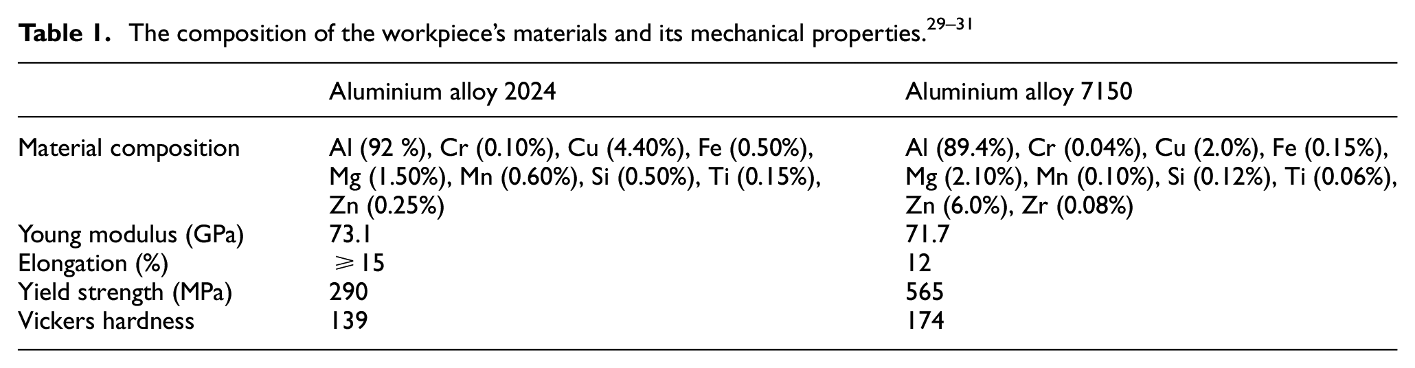
Experimental approach
This experiment employs two types of aluminium, namely aluminium alloy 2024 and aluminium alloy 7150, which are arranged in stacks with 2024 on top and 7150 on the bottom. This arrangement is consistent with Airbus UK’s current practise. The dimension of the two plates measured 22 cm × 22.5 cm and are 9.33 and 12.6 cm thick, respectively. Table 1 displays the technical data for these two materials. This stack is clamped to the centre of a Kistler Dynamometer 9257A, a 3-Channel Amplifier type 5070 equipped with data acquisition system, where all force signal data was analysed using Dynoware software. Figure 1(a). depict the experimental setting diagram. The tool points used are cemented tungsten carbide twist drills NL55 TL 94 from Kyocera Unimerco Ltd in Denmark. The tool point measures 6.4 mm in diameter and has a point angle of 130° and a helix angle of 40°. Experiments were carried out on the CNC vertical machining HAAS Automation VF-2SS without the use of any coolant or dry cutting. Vickers hardness was measured for each plate prior to the test using a Buehler Micromet 5103 hardness testing machine. The hole diameter was measured after machining with a Nikon LK G-90C, a coordinate measuring machine (CMM) equipped with Camio Software for data acquisition. As responses, cross-sectional diameters were measured at 1, 4.7, 8, 10.3, 15 and 19.5 mm depths from the top surface. Assessment on tool wear for each drill after completed nine holes was conducted using a Keyence 500 optical microscope. The holes’ average surface roughness (Ra) was determined using the Taylor Hobson surface roughness Surtronic 25 with evaluation length of 2.5 mm.
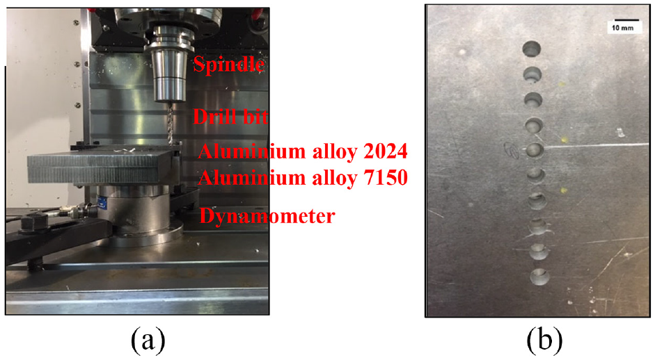
(a) Arrangement of tools and materials in machining and (b) top viewed of drilled holes.
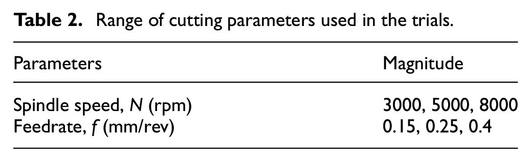
The cutting parameters for the experiment were chosen based on a review of the literature on drilling with carbide cutting tools as well as existing practises at Airbus UK. Following a review of all cutting parameters, feedrates of 0.15, 0.25 and 0.4 mm/rev were established with spindle speeds of 3000, 5000 and 8000 rpm (as shown in Table 2). With a 10-mm centre spacing between each successive hole, through holes were drill in rows.
Range of cutting parameters used in the trials.
Results and discussion
Measurement of thrust force
Thrust force signals in relation to the cutting time in the drilling process of stack materials were as presented in Figure 2. In general, five main stages occurred in the cutting process before the tools were retracted from the work material.
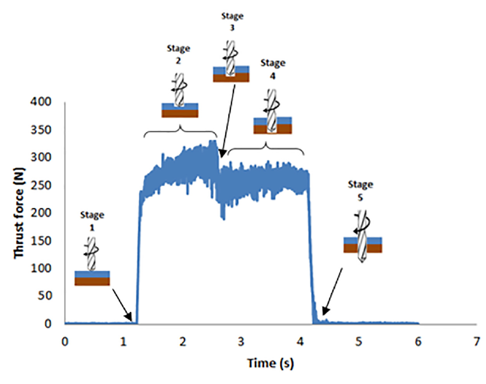
Thrust force profiles in relation to the stages in drilling aluminium alloy stack.
In Stage 1, a sharp increase of force signal was captured as the drill chisel edge touched the surface of the first work material. This was indicative of the chisel edge being a major force contributor to the overall thrust force in drilling machining. In Stage 2, the thrust force progressively increased which eventually reached its maximum value as the cutting edge cut the first layer of the workpiece. This step was then followed by the drill penetrating into the second material (Stage 3). The advance of the chisel edge into the interface area showed a clear abrupt in thrust force profile due to a sudden change in material hardness between stack materials. Once the cutting edge began to cut the second material (Stage 4), a similar pattern of force signal was observed as with the first material, although the profile appears more stable, likely due to the lower material elongation characteristics of the 7150-aluminium material. This was subsequently followed by Stage 5 where it was observed that the thrust force rapidly decreased to zero, a steep reduction which implied that the drill had completed its penetration of the stack and continued on to the retraction process.
Effect of cutting parameters on average thrust force
In all instances, the mean thrust force for each material figured out based on the drilling time between the two regions. Using the thickness of material in relation to cutting time, drilling time could then be ascertained. Figure 3(a), (b) and (c) show three different types of thrust force-time signal recorded in all the trials. Figure 3(a) presents a uniform thrust force profile in which it was not significantly different in force between the onset of cutting in the first layer of material until completion and tools retracted from work material. Figure 3(b) shows a considerable dynamic pattern during the cutting process indicating problems with chips evacuation. The massive fluctuation pattern of force signals at the end of cutting in Figure 3(c) indicates retraction issues. During drilling, aluminium was alternately built up and evacuated from the drill flutes causing the thrust force signals to rise and fall.
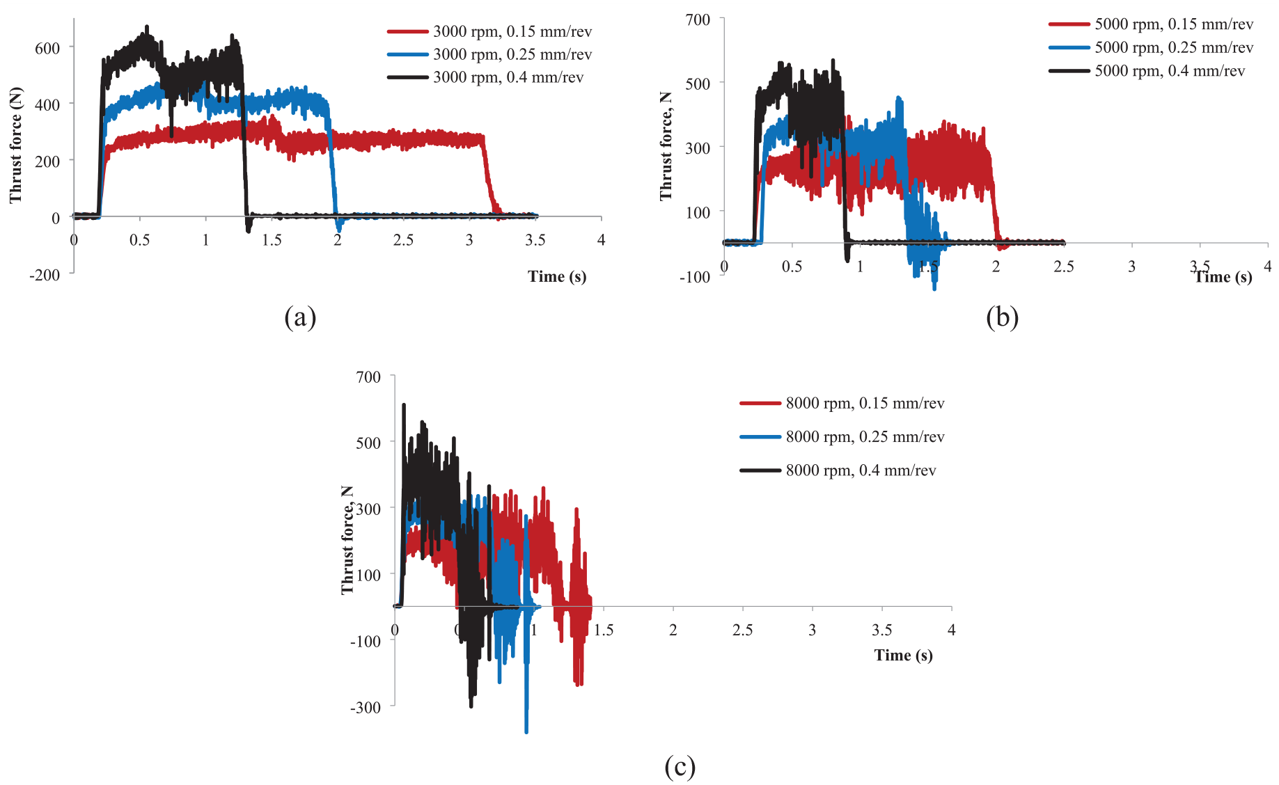
Three different thrust force profiles in uncoated drills: (a) a uniform curve of thrust force, (b) a considerable transient pattern during the cutting process and (c) a massive transient pattern of force signals.
A uniform thrust force trend was observed when drilling at 3000 rpm regardless of feedrate value (see Figure 3(a)). No drastic rise or drop and no significant spikes were presented suggesting a smooth drilling process with no prominent aluminium adhesion on the tools. The results also illustrate that the forces apparently increased as feedrate rose. Between 0.15 and 0.4 mm/rev feedrates, a 20%–33% increase in average thrust force was observed for each work material. Any increase in feedrate increases chip cross-sectional area and chip volume per unit time between the stack workpiece and tool; as such, the metal demonstrated resistance to rupturing, resulting in a higher thrust force.
A larger fluctuation pattern of force response was observed at spindle speed 5000 rpm and feedrates 0.15 and 0.4 mm/rev (Figure 3(b)). A significant variation in the average thrust force value could be ascribed to an increase in friction between cutting edge of tool and hole wall. It was also evident from the graph that an increase of spindle speed decreased the average force value. For example, using the same feedrate of 0.15 mm/rev, the average thrust force at 5000 rpm was 253 N for aluminium alloy 2024 and 248 N for aluminium alloy 7150 respectively, with a reduction of about 8%–17% compared to the condition at 3000 rpm. A similar reduction was also recorded at the feedrate of 0.4 mm/rev where the average thrust force dropped about 84–95 N from the lower feedrate condition. As a result, the friction that occurs between the workpiece and tool cutting edge increases in line with the temperature at the cutting zone as the cutting speed increases. This condition causes a thermal softening effect, which causes the material to soften and thus reduces the cutting force.
A massive transient pattern of thrust force responses was recorded in all cutting parameters of 8000 rpm (Figure 3(c)). The interaction and engagement between the drill margin and the hole wall could be the cause of these significant fluctuations, or a sign of excessive material adhesion on tools which resulted in the chip being unable to exit easily through the drill flute.
Figure 4 shows the average thrust force value for all the cutting parameters tested in the study. The lowest values of thrust force for both materials were obtained at the high spindle speed of 8000 rpm and the highest thrust force values derived at 3000 rpm low spindle speed for all three feedrates. Average thrust force response values exhibited a nearly steady-state trend at 3000 rpm, but significant fluctuation and scattering were observed at 5000 and 8000 rpm.
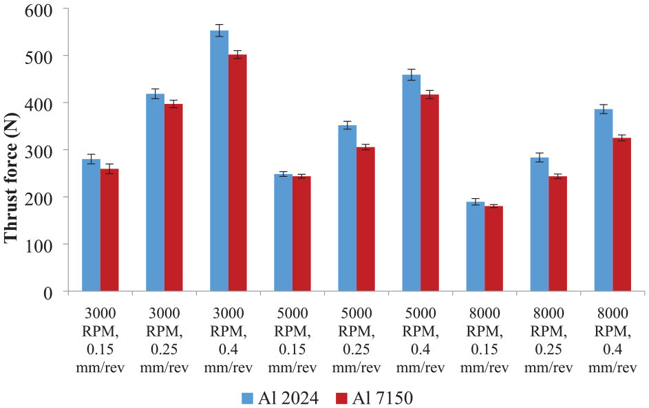
Variations of average thrust force recorded in experiment.
The average thrust force generated by aluminium alloy 7150 was less than that generated by aluminium alloy 2024 across all cutting parameter ranges used in the experiments. This could be due to the higher ductility of aluminium alloy 2024 and its sticky behaviour. The sticky property of the materials caused the formation of thicker chips during the cutting process, resulting in a higher thrust force required to shear the chips from the workpiece material.
Effect of cutting parameters on cutting power and energy intensity
Several functions, including plastic deformation in shearing, chip formation, and energy losses throughout the machine tool, require electrical energy or cutting power as input source during the machining process. 32 Variation in cutting conditions applied to the drilling affected cutting power. Equation (1) calculates drilling power, P (Watts), using the thrust force F (N) and the linear feed V (mm/min).
Figure 5 shows the change in power for different cutting speeds and feedrates tested in the experiment. From that figure there is an apparent proportional relationship between these two responses: an increment on the cutting speed (
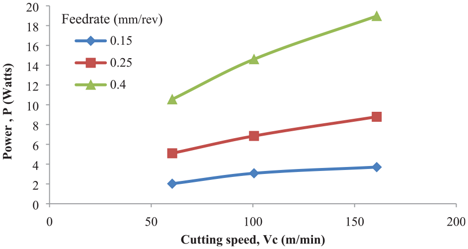
Effect of cutting speed on cutting power.
The drilling energy (E) is calculated by the product of drilling time t(drilling), material removal rate (MRR) and specific cutting energy (εc) as expressed in equation (2).

Figure 6 compares the breakdown of energy required according to cutting parameter range. Strong evidence of reduced cutting energy was found when machining at high spindle speed. The fact that increased cutting speed results in less time between the cutting tool and the workpiece, as illustrated in Figure 7, may account for this result. A shorter interaction time results in the least amount of build-up of workpiece material at the cutting edge, which in turn reduces drilling energy. In contrast, drilling at lower spindle speed consumes more energy due to the longer interaction duration. In order to minimise cycle time and cutting energy, higher spindle speed and feedrate are therefore recommended.
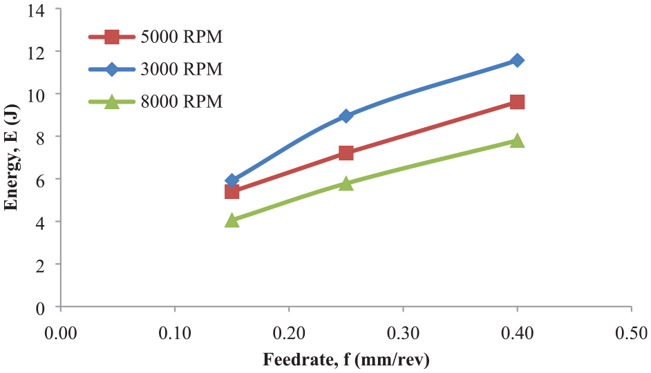
Variations of energy consumption in experiment.
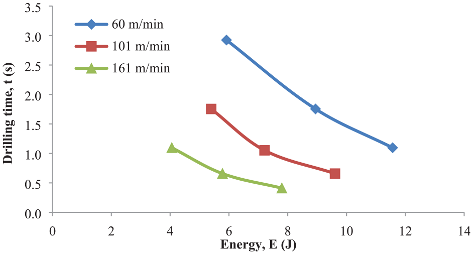
Effect of drilling time on cutting speed and energy.
Effect of cutting parameters on tool wear
Figure 8 shows the microscopic images of the flank drill faces for all cutting conditions. Both feedrate and cutting speed were found to significantly impact tool wear. Chipping was generally more severe at higher cutting parameters, with a maximum fracture of 0.217 mm at the drill cutting edge corner at 8000 rpm and a feedrate of 0.4 mm/rev. Apart from this chipping, drills at cutting parameters of 8000 rpm, 0.15 and 0.25 mm/rev experienced considerable abrasive wear leading to maximum flank wear of 0.1 and 0.2 mm respectively. Therefore, it could be hypothesised that spindle speed 8000 rpm and feedrate 0.4 mm/rev are not suitable for machining aluminium alloy 2024/aluminium alloy 7150 stack materials. In this experiment, the main wear mode of the drills was chipping and flank due to abrasion. With the exception of the 3000 rpm; 0.15 and 0.25 mm/rev and 5000 rpm; 0.25 mm/rev cutting parameters, the flank faces of all drills experienced wear. Chipping was observed on the peripheral corner at drill margin whilst abrasion occurred primarily along the cutting edges.
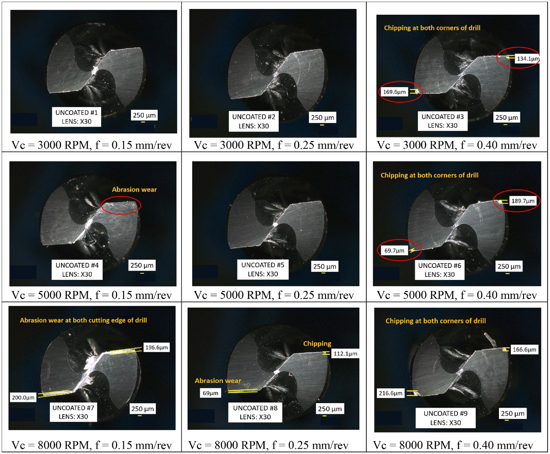
Microscope images of drill flank face in all cutting parameters.
Effect of cutting parameters on hole wall roughness
Figure 9 illustrates the Ra variations in relation to the feedrate at three different spindle speeds. The comparative pattern of Ra in lower spindle speed however did not appear when drilling was conducted at 8000 rpm. Since the drill margin changed due to chipping of the cutting tool, the Ra fluctuations observed despite increase in spindle speed could be attributed to tool wear. A massive scratch mark or little cavities were evident on hole surfaces where drills experienced chipping as shown in Figure 10, happened mostly at cutting speed of 8000 rpm. As a result, it can be assumed that as the spindle speed increases, the interaction between the drill margin and the surface inside the hole results in a variation of Ra. At lower spindle speed, the effect of feedrate on the Ra was in agreement with the thrust force findings. Due to the increased feedrate, the amount of material scratched per revolution would be increased as well, for instance at 3000 and 5000 rpm, the Ra in both aluminium alloy 2024 and aluminium alloy 7150 gradually increased as feedrate rose. In addition, it was discovered that when the speed was increased to 8000 rpm, the Ra in 7150 was greater than 2024, whereas the opposite was true for low and medium speeds. This could be attributed to tool wear and Ra inside the hole. The micrographs reveal that at 8000 rpm, regardless of feed rate, both drill corners of all cutting tools exhibit chipping, causing deep scratches in all materials. Due to the fact that larger scratches occurred more frequently in 7150 than in 2024, it was hypothesised that the chipping began in 7150 material prior to the drills being retracted from the holes.
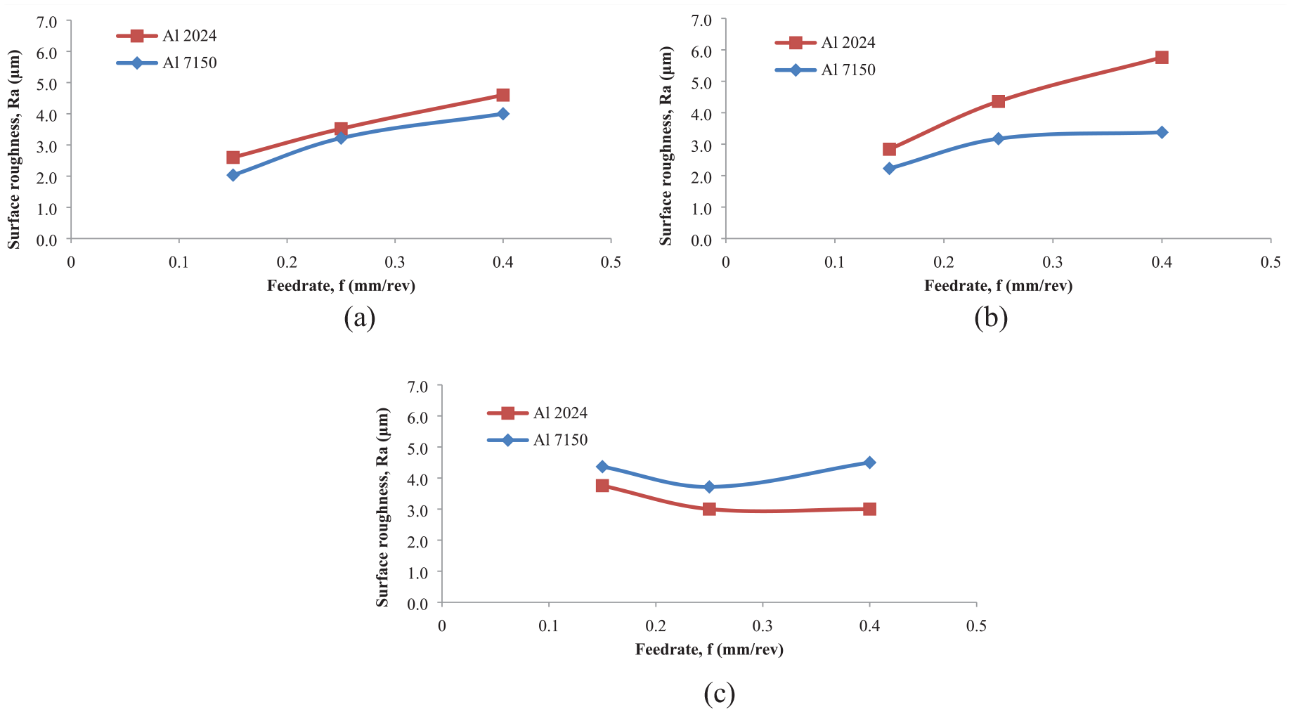
Variation of Ra in holes at spindle speed of (a) 3000 rpm, (b) 5000 rpm and (c) 8000 rpm.
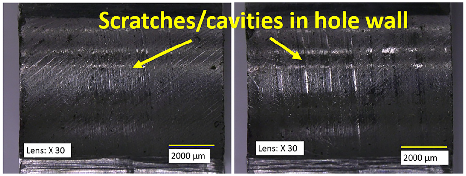
Scratches or cavities in hole wall caused by tool chipping.
Effect of cutting parameters on hole diameter deviation
Deviation of diameter is a critical factor that is frequently used in the industry to evaluate the quality and dimension accuracy of drilled holes. In this study, the correlation between diameter and thrust force was analysed. Figure 11 shows the average deviation of hole diameter for each aluminium alloy workpiece in the experiment.
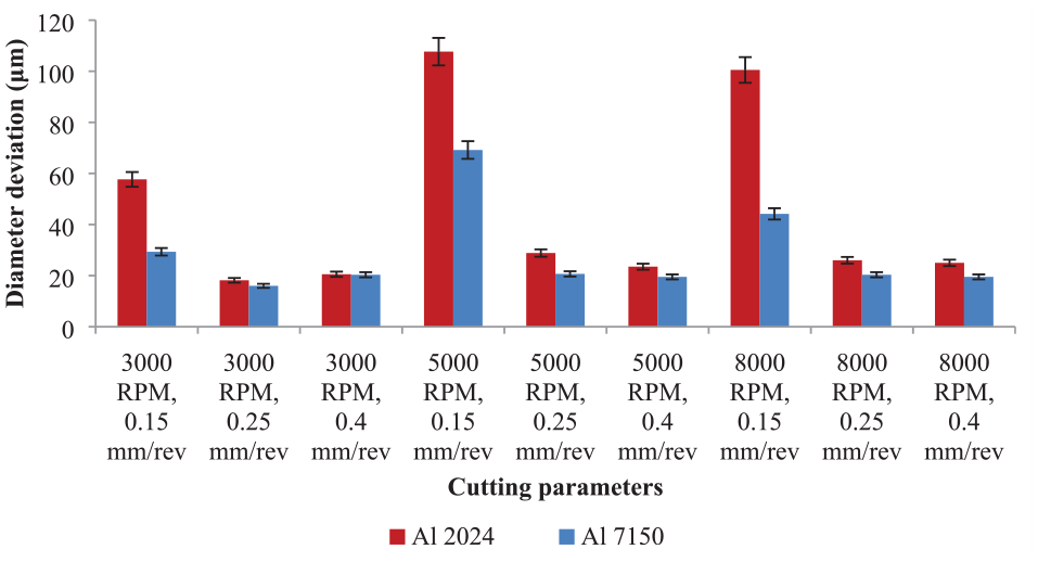
Average deviation of hole diameter for each workpiece alloy.
With the exception of the three conditions at 0.15 mm/rev where the holes were noticeably oversized, from the graph it could be ascertained that the diameter deviations for the majority of cutting parameters tested were satisfactory taking into consideration the allowable deviation value of 50 μm. Although not shown here, in terms of the individual components, most of the holes had a pronounced barrelling effect, reaching their maximum cross-sectional diameter in the middle and then reducing to their minimum diameter at the bottom. This feature could be attributed to the effect of drill wander during the initial entry to the upper part of workpieces. All cutting parameters showed a greater deviation for the first material (aluminium alloy 2024) than for the second material (aluminium alloy 7150). The significant diameter differences between the upper and lower part of the holes could be explained by properties of aluminium alloys employed in this study. Consistent with the literature, aluminium alloy 2024 produces greater deviation due to higher elongation percentage compared to aluminium alloy 7150.
From the chart, it could be seen that cutting parameters of 0.25 mm/rev and 3000 rpm resulted in lower diameter deviation values. In both aluminium alloys 2024 and 7150, the deviation from nominal diameters was less than 20 µm. A significant feature to emerge from the data comparison was drilling at feedrate 0.15 mm/rev irrespective of speed of spindle produced consistently higher deviations over the experiment duration especially at spindle speed 5000 and 8000 rpm. However despite this observation, the impact of cutting speed and feedrate on the great alteration of diameter deviation was not conclusive that is, at a reduced spindle speed, an increase in feedrate did not result in higher variations of diameter. Similar findings were recorded at higher spindle speed. However from a comparison of tool wear in the nine cutting conditions one could infer that the particular drills used in these two cutting conditions had high abrasive wear possibly due to the extreme fluctuation of thrust force signals as shown in Figure 3(c). Evidence of chatter in the hole surface was observed after machining at cutting parameters 5000 (shown in Figure 12) and 8000 rpm. Chatter, as described by Cheng 33 is the unwanted excessive vibration in the machining process, occurs due to tool and workpiece displacement that excites the structural modes of the system. These vibrations affect machine tool productivity and the quality of the machined surface.
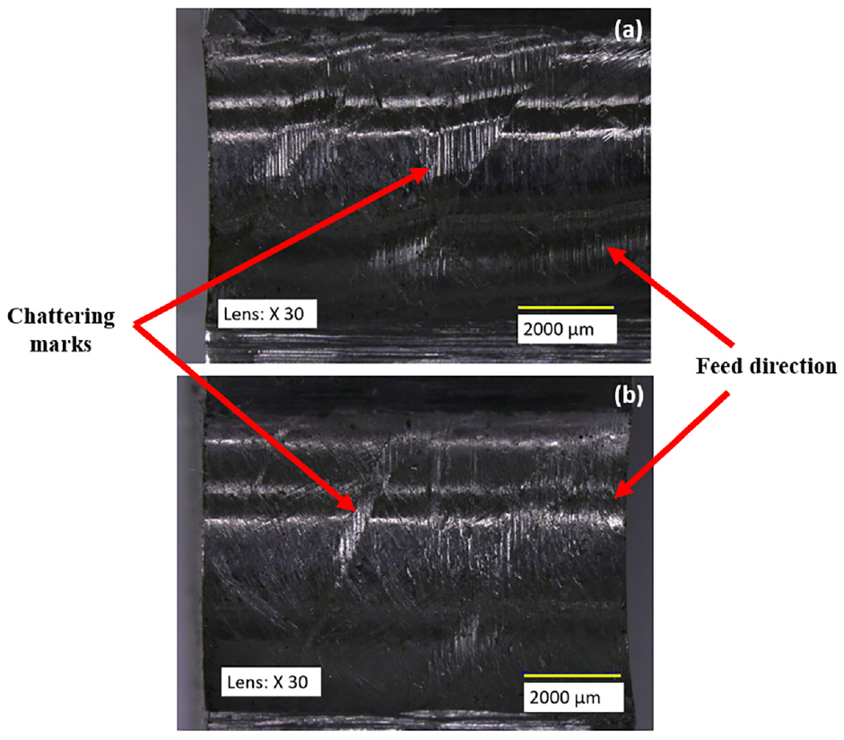
Surface of drilled holes produced at 5000 rpm for (a) aluminium alloy 2024 and (b) aluminium alloy 7150.
Conclusion
Uncoated drills are used in this study to see how cutting parameters affect thrust force, tool wear, diameter deviation and surface roughness (Ra). Dry drilling experiments were done on the aluminium alloy 2024/aluminium alloy 7150 stack. A summary of the key observations is as follows:
(i) Due to differences in material properties, the average thrust force for aluminium alloy 7150 was lower than that for aluminium alloy 2024, regardless of the cutting parameters used in the study. A uniform trend of thrust force could be achieved by drilling the aluminium alloy stack materials at the lower cutting speed of 3000 rpm.
(ii) From an energy perspective, lower consumption was achieved when machining at higher cutting speed. Further study on this aspect is therefore recommended to ascertain the viability of compromising tool life by increasing speed and/or feed to reduce cycle time.
(iii) Drilling at feedrate of 0.15–0.25 mm/rev and spindle speed of 3000–5000 rpm is recommended to avoid chipping and tool edge fracture.
(iv) The deviation in diameter indicates that cutting parameter of 0.25 mm/rev and 3000 rpm resulted in good dimensional accuracy compared to other parameters tested in the experiment.
(v) This study concludes that using mid-range spindle speed and feedrate for dry drilling of aluminium alloy stack materials is a good compromise in terms of reducing drill interaction time and energy input while improving overall hole quality.
Footnotes
Acknowledgements
The authors acknowledge support from Northern Aerospace Technology Exploitation Centre, Teer Coatings Ltd, Kyocera Unimerco Ltd and Airbus.
Declaration of Conflicting Interests
The author(s) declared no potential conflicts of interest with respect to the research, authorship, and/or publication of this article.
Funding
The author(s) received no financial support for the research, authorship, and/or publication of this article.