
Abstract
Considering the constantly increasing demand for aircraft products, the development of automatic drilling-riveting machine tool systems is discussed in this paper. A structural conceptual design method considering both efficiency and quality is proposed. Particularly, a drilling-riveting machine tool system including single-column machine tool, light-weight end-effector, and assisting fixture system is built. The positioning error coordinates variation model is analyzed, and the ranges of reasonable processing parameters are determined. An experiment is conducted on the developed system to show satisfactory drilling-riveting quality and efficiency: compared with the position error of other similar systems, the position error with 0.082 mm is reduced by 41.42%, and the accuracy of aperture reaches H8, the rivets head height error ≤0.8 mm, and drilling and riveting efficiency can reach 6/min and 8/min.
Keywords
Introduction
Aircraft assembly is an important stage in aircraft manufacturing, and rivet connection is the main joining method during aircraft assembly. Because thousands of rivets are required for aircraft products, drilling-riveting always costs over half of assembly cycle time. Moreover, the quality of drilling-riveting directly affects the mechanical property of the final product, such as fatigue properties and water tightness. Compared with traditional manual drilling-riveting methods, automatic drilling-riveting technology has advantages of high processing efficiency, low long-term cost, and high assembly quality. 1 Thus, the use of automatic drilling-riveting system is an inevitable trend with the constant update and the increased demand for aeronautic products.
The development of automatic drilling-riveting system for specific aviation products has been widely concerned for years. C-frame and vertical drilling-riveting system integrated with one-up assemble fixture have been produced by GEMCOR which is one of the main auto drilling and riveting equipment suppliers, they have developed a series of representative products including G2000, G86, and Wing Riveting System (WRS) have been used for several Aircraft Program, including Boeing, Airbus, Embraer, and Bombardier. 2 E7000 high-speed CNC fuselage riveting cell and mobile robotic drilling-fastening systems have been launched by Electroimpact since 2008. E7000 have ability to realize rapid assembly of large curvature panel since its riveting speed can reach 15–20/min, 3 and the mobile robotic drilling-fastening system has been applied to drilling, countersinking, and measuring on large aircraft trailing edge flaps production lines for Boeing aircrafts.4,5 In order to meet specific processing and space requirements, such as 360° drilling-riveting of fuselage panel, processing of metal and CFRP components, and aircraft cargo door whose maximum working space of the structure is 5 m × 6 m, 6 BROTJE developed a series of representative assembly cells, including C-Frame Panel Assembly Cell (CPAC), Integrated Panel Assembly Cell (IPAC), and Robot Assembly Cell (RACe).7,8 Additionally, many automated drilling-riveting systems are developed by aerospace enterprises through technological cooperation with universities in recent years.9,10 Aircraft digital assembly team of Zhejiang University began to develop automatic drilling-riveting machine system in 2014, and a dual-machine based drilling and riveting system is developed to realize aircraft panel drilling, socketing, diameter measurement, rivets feeding, squeeze riveting, and milling.11–16 Chengdu Aircraft Industrial corporation cooperates with universities such as Northwestern Polytechnical University developed a series of automatic drilling-riveting assembly robot systems for a certain type of aircraft wing panel components.17–19 In order to improve drilling and riveting quality, the positioning variation modeling 20 and the compensation module 21 have been extensively studied for the final positioning accuracy of a system by researchers. Similarly, the prediction and control of interlayer burrs and other machining defects has been extensively studied to find suitable process parameters.22,23 Significantly, different drilling and riveting systems have different positioning methods and optimal ranges of process parameters. Therefore, relevant research should be carried out according to the characteristics of the constructed system. Based on the research status and application data of current automatic assembling systems, it can be seen that automatic drilling-riveting systems mostly are machine tool systems and robot systems, they have different characteristics and application objects. Drilling-riveting machine tool system is bulky, rigid, and stable so that is suitable for open-plan shape components and low-stiffness structures. Drilling-riveting robot systems are suitable for small batches and complex shape rigid components because of their cost, accessibility, and less rigidity. 24 Currently, the contradictions between precision and efficiency, stiffness, and accessibility are the key problem restricting the development of automatic drilling and riveting system. To solve the problems, this paper first proposed a structural conceptual design method considering both function and lightweight, and the positioning coordinate variation model is analyzed. Then an automatic drilling-riveting machine tool system is built for different sizes of aviation long box products. Finally, a series of tests are conducted to determine reasonable ranges of processing parameters, and the performance of the development system is verified based on experiment results.
Methods of automatic drilling-riveting machine tool system development
Conceptual structure design to function and lightweight
An automatic drilling-riveting machine tool system includes a mechanism for mobile positioning, a fixture for assisting, and an end-effector with several complex and specific machining functions. Generally, the realization of a concrete function usually has several different implementation solutions, and the lightweight of end-effector can reduce the positioning time to improve processing efficiency. However, the comparison of different solutions is neglected by traditional design methods.25,26 In order to determine the optimal structure at conceptual design phase, a design method considering the interaction between the realization of processing functions and lightweight of mechanical structure is proposed by combining qualitative and quantitative evaluation.
Firstly, the end-effector is divided into several functional modules according to design objectives. Then alternative solutions of each functional module are designed, and the k-th installation solution of the j-th structural solution of module labeled with i is noted by M
i
S
j–k
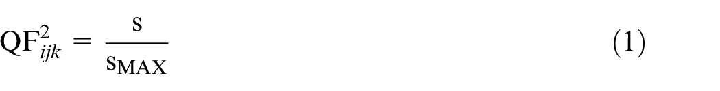
. Finally, and most importantly, each solution is evaluated quantitatively from three aspects including functional requirements of individual modules, functional requirements of the entire end-effector, and lightweight of structure. In terms of functional requirements, Quality Factor (QF
ijk
) consists of

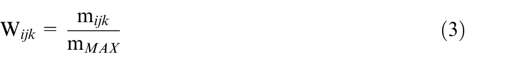
The purposes of the conceptual structure design method are to minimize the weight factor
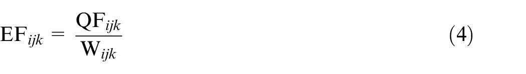
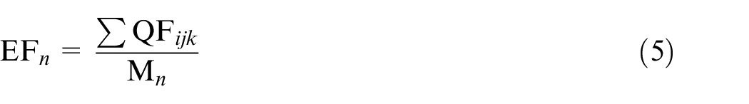
wherein, Mn is the weight of the entire structure. Based on the implementation of the functional requirements and light weight, the solution with the highest EF n value is chosen as the best solution.
Positioning coordinate variation model
In order to realize quick and accurate positioning, a coordinate variation model is established to describe the processing position and posture of the system. A series of coordinates system, including base coordinate system {B}, assembly fixture coordinate system {F}, workpiece coordinate system, machine tool coordinate system {S}, end-effector coordinate system {T}, and the i-th task coordinate system {Tag-i}, are built. In this paper, coordinate system {B} is set to coincide with coordinate system {S} for the convenience of calculation. Tool Center Point (TCP) and drilling-riveting direction are taken as the origin and the Z-axis direction of coordinate system {T}. The center of the i-th hole (tag- i ) and the axis of holes are set as the origin and the Z-axis direction of coordinate system {Tag-i}. The axis of holes are obtained by calculating the surface normal. While the TCP and the drilling-riveting direction are coincident with the tag- i and the Z-axis direction of coordinate system {Tag-i} during drilling and riveting, the positioning can be realized, and the ideal coordinate variation model is shown as Figure 1.
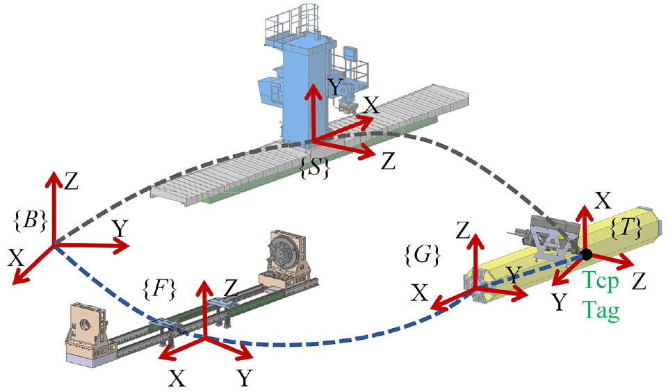
The ideal coordinate variation model.
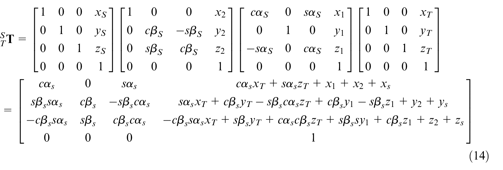
According to the homogeneous transformation formula, the coordination of
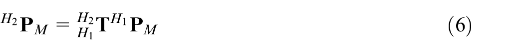
and
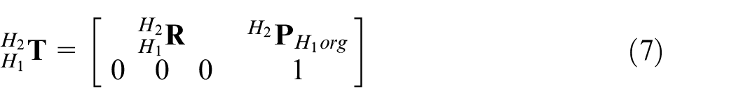
wherein

and

Wherein,
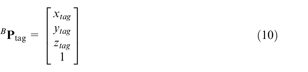
so the positioning information are obtained. TCP and tag- i have the same coordinates in {B}, and the z-axis in {T} are coincident with the Z-axis in {Tag-i}, these relationships can be formalized as

and

Development of automatic drilling-riveting machine tool system
Conceptual structure design of an automatic drilling-riveting machine tool system
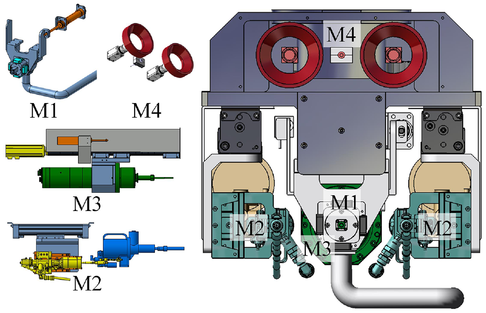
An aviation long box products is selected as an example to verify the proposed method for the development of automatic drilling-riveting system in aircraft assembly. The length range of the products is from 6500 to 11,000 mm, and the cross-section is a polygon with a side length of more than 0.75 m. More than 3500 up to 6000 points are demanded by aluminum alloy skins connection in a single product, and two kinds of diameters and six kinds of specifications of rivets are used. The assembly requirements of products for this process to be feasible are as follows: the accuracy of aperture reaches H8, the error of hole position ≤0.1 mm, no visible interlaminar burr, rivets are inserted accurately, and the rivets head height error ≤1 mm after riveting. There are three procedures involved in the assembly of products. The first stage is drilling holes for all sides of the long box products. Then the products are hoisted away for other processes such as deburring, arranging electrical conductors, and coating adhesive. At the last stage, the products are hoisted back to secondary assembly and then rivet at previous stations. In conclusion, the drilling-riveting requirements of the aviation long box product include quality, efficiency, accessibility, and stability, which are mainly reflected in 360° processing area, complex processes, heavy workload, and the need to control the axial deformation and the twist deformation of the product. Therefore, a machine tool equipped with an auto drilling-riveting end-effector is designed considering both efficiency and quality, and an assembly fixture system is adopted to solve the contradiction between stiffness and accessibility, as shown in Figure 2.
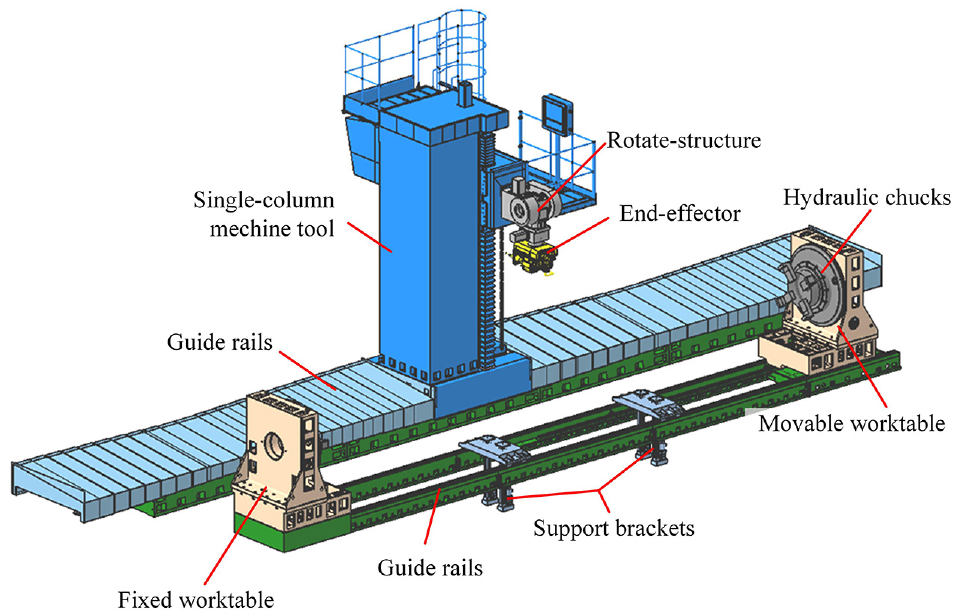
Conceptual design of the drilling-riveting machine tool system.
As the positioning equipment, the machine tool has five freedoms including X/Y/Z-axis linear motions as well as A/B-axis rotary motions around X-axis and Y-axis. The machine tool consists of ground rail, single-column machine tool, and A/B axis rotate-structure. The X-axis movement is realized by the column on the ground rail which is equipped with a grating ruler to realize accurate positioning, and the column is driven by gear racks through a reducer. The Y-axis movement is realized by the headstock which is driven by a servo motor and moves vertically along with a pair of ball screws. The Z-axis movement is realized due to the headstock which is driven by an AC servo motor and moves horizontally along with a pair of ball screws. The A/B axis rotate-structures are driven by two rotary motors. Furthermore, different sizes of long box products are clamped and flipped steadily by assembly fixture with reasonable design. Products are clamped by hydraulic automatic indexing chucks which are installed in one fixed worktable and one movable worktable respectively and permitted to rotate around the central axes of products. Two movable support brackets are installed on a pair of guide rails between fixed worktable and movable worktable to lift and support products during processing.
As the core equipment of an automatic drilling-riveting system, the end-effectors have functions including benchmark detection, normal vector detection, tool change, drilling, rivets feeding, and riveting with different specifications of rivets. The end-effector has five global functional requirements as following: requirement I is simple and compact structure, requirement II is the operation accessibility during debugging, requirement III is avoiding interference during changing drill tool, requirement IV is avoiding interference and collision among moving components, requirement V is enough space for processing, requirement VI is the balance gravity center, should be taken into account. According to the mentioned method above, the end-effector is divided into five modules: pressuring module (M1), riveting module (M2), drilling module (M3), detection module (M4), and frame module (M5).
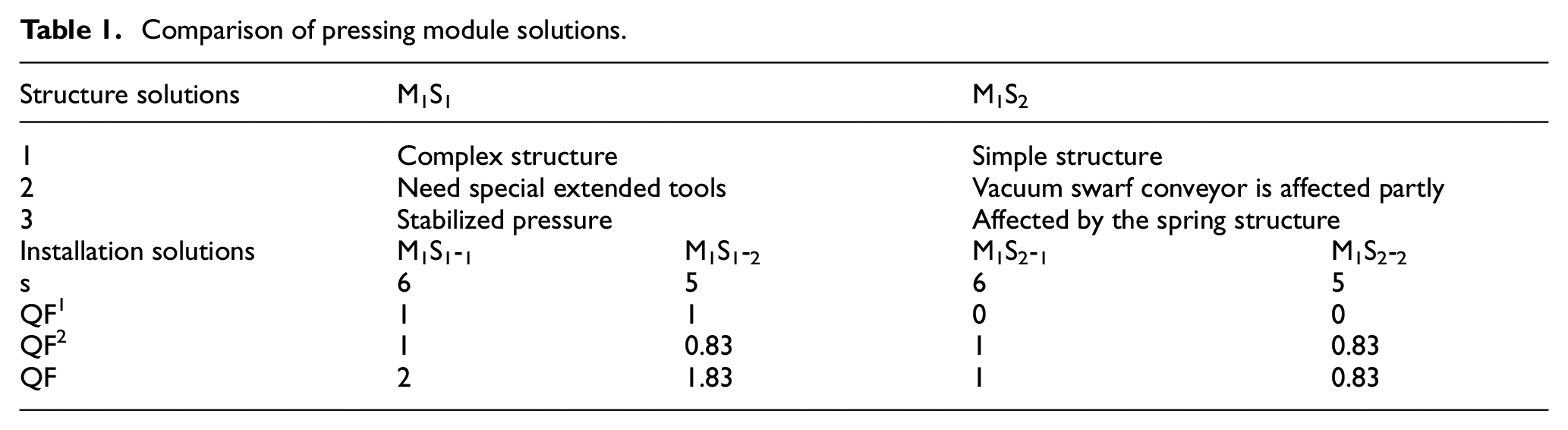
As for the pressing module, a cylinder of the pressing module is used to push the pressure foot to move along guide rails, and the pressing force can be controlled by adjusting the proportional valve of the cylinder. Two structure solutions are proposed for the step structure of workpieces: M1S1 is an integrated presser foot as shown in Figure 3(a). M1S2 is an alterable structure as shown in Figure 3(b). Two installation solutions of each structure solution are hanging configuration M1S j -1 and side configuration M1S j -2. However, frame plates of M1S j -2 sides are demanded to install cylinders, so that M1S j -2 has a negative impact on tool change, cannot meet the global requirement III. Therefore, s values of scheme M1S j -1 and M1S j -2 are 6 and 5 respectively, QF 2 values are 1 and 0.83 respectively according to equation (1). In addition, although M1S2 needs to customize special extended tools for different product step structures, it has more stable pressing force and better cleaning effects, which is essential to ensure the quality of drilling. Therefore, M1S1 has better assurance ability of functional requirements of M1, and QF1 values of M1S1 and M1S2 are 1 and 0 respectively. The comparisons of M1 solutions are shown in Table 1. M1S1-1 with the highest value of QF is considered the best assurance ability of processing functions.
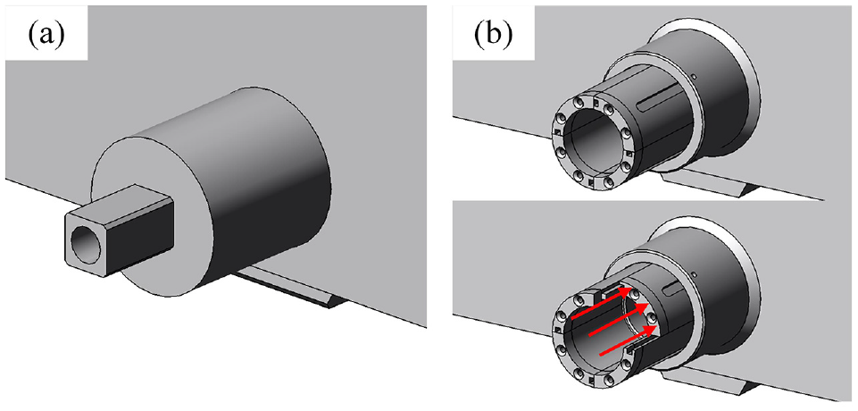
Structure of the pressing module: (a) integrated structure of presser foot and (b) alterable structure of presser foot.
Comparison of pressing module solutions.
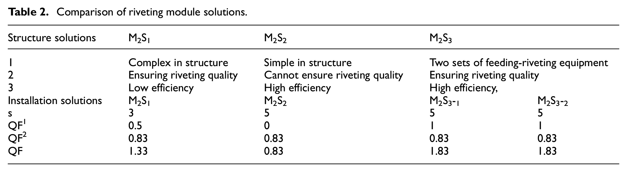
As for the riveting module, a rivets feeding device and a riveter are integrated into distributed structure M2S1 as shown in Figure 4(a). Integrated riveters with functions of rivets feeding and riveting are adopted by M2S j , as shown in Figure 4(b). An integrated riveter with the largest gauge of the two diameters is adopted by M2S2, and two integrated riveters with different gauges are adopted by M 2 S3. Two solutions of M2S3 are proposed for installation, the one is M2S3-1 whose integrated riveters are installed on both sides of the drilling module, and another is M2S3-2 whose integrated riveters are installed on one side. M2S1, M2S2, and M2S3-2 cannot meet the global requirement VI, M2S1 cannot meet the global requirements I and II, and M2S3-1 cannot meet the global requirement II. The comparisons of M2Sj-k are shown in Table 2. Among solutions of M2, M2S3-1 and M2S3-2 both have better assurance ability of processing functions.
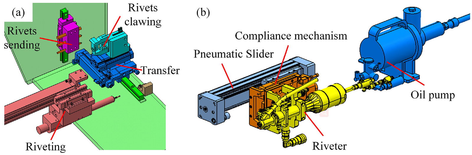
Structure of the riveting module: (a) distributed structure and (b) integrated riveter.
Comparison of riveting module solutions.
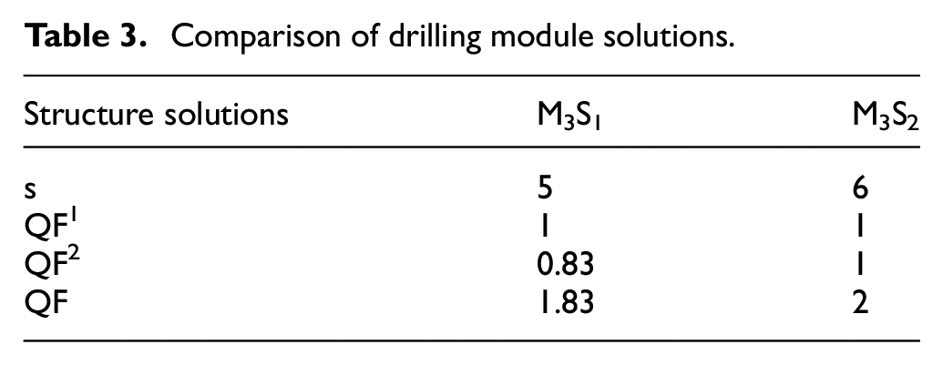
As for the drilling module, a high-speed spindle moves along a pair of ball screws and guide rails to realize the axial motion. In order to avoid damaging the skins of products, a contact displacement sensor is adopted to monitor the depth of drilling. Two solutions are proposed as driving by the motor directly and driving by the motor through a transmission, named M3S1 and M3S2, as shown in Figure 5. The weight of M3S2 is concentrated on the front due to the spindle moves forward during drilling, so M3S2 cannot meet the global requirement VI. The comparisons of M3S j are shown in Table 3. M3S2 is the best choice in terms of the assurance ability of processing functions.
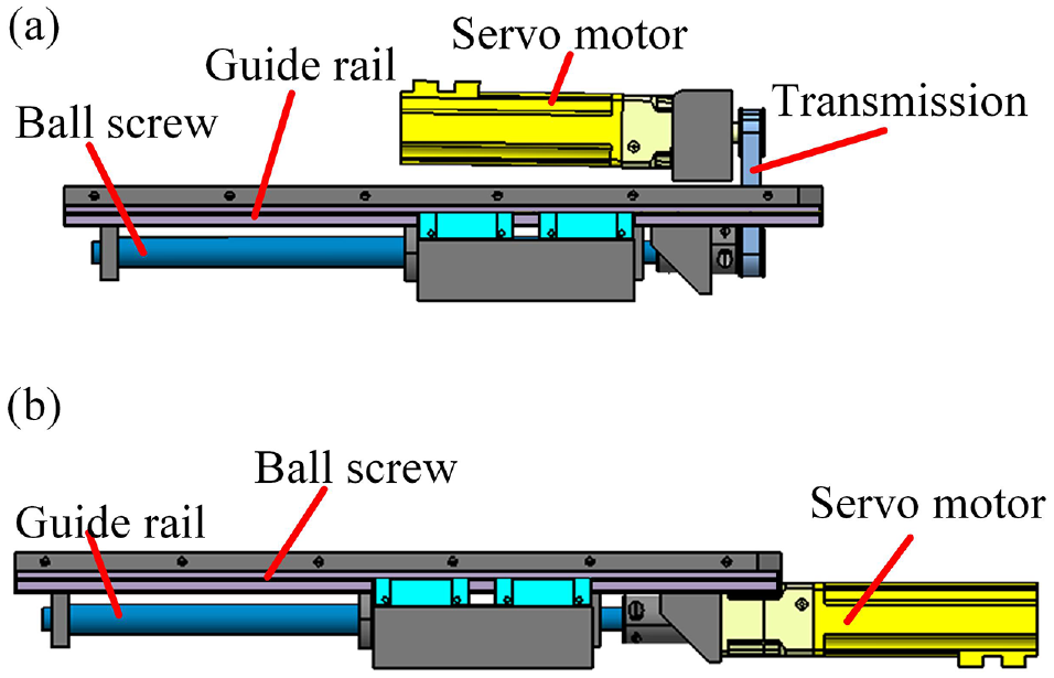
Structure of the drilling module: (a) driving through a transmission and (b) driving directly.
Comparison of drilling module solutions.
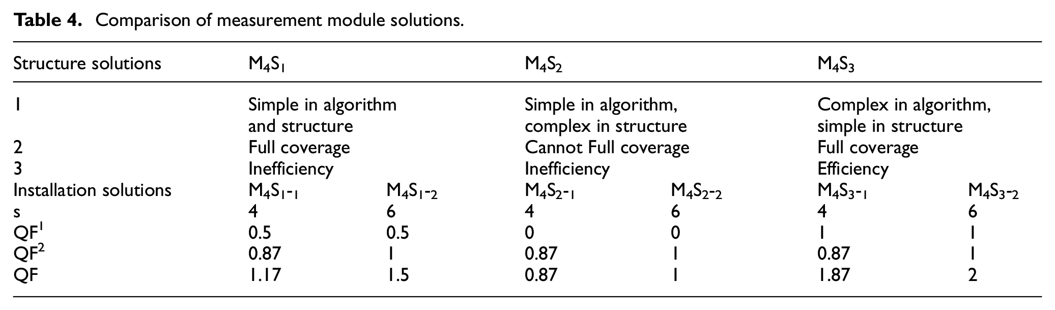
As for the detection module, three solutions are proposed. A line scanner and four laser displacement sensors are adopted by M4S1 to realize benchmark detection and normal vector detection. A line scanner and a contacting displacement sensor are adopted by M4S2, and the contacting displacement sensor is installed in front of the pressure foot. A set of binocular cameras are adopted by M4S3. Two installation solutions of M4 are proposed as top configuration and side configuration respectively, named M4S j -1 and M4S j -2. Among the solutions of M4, M4S3-1 cannot meet the global requirements II and IV. The comparisons of M4S j - k are shown in Table 4. M4S3-2 shows the best performance in terms of the assurance ability of processing functions.
Comparison of measurement module solutions.
The frame module is reliably connected with the machine tool by a flange structure which is arranged on the top of the end-effector. For the convenience of debugging, an area on top of the frame module is reserved for proportional valves and other components. Because the structure of the frame module depends on the installation solutions of other modules, the functional requirements of M5 are the global requirements.
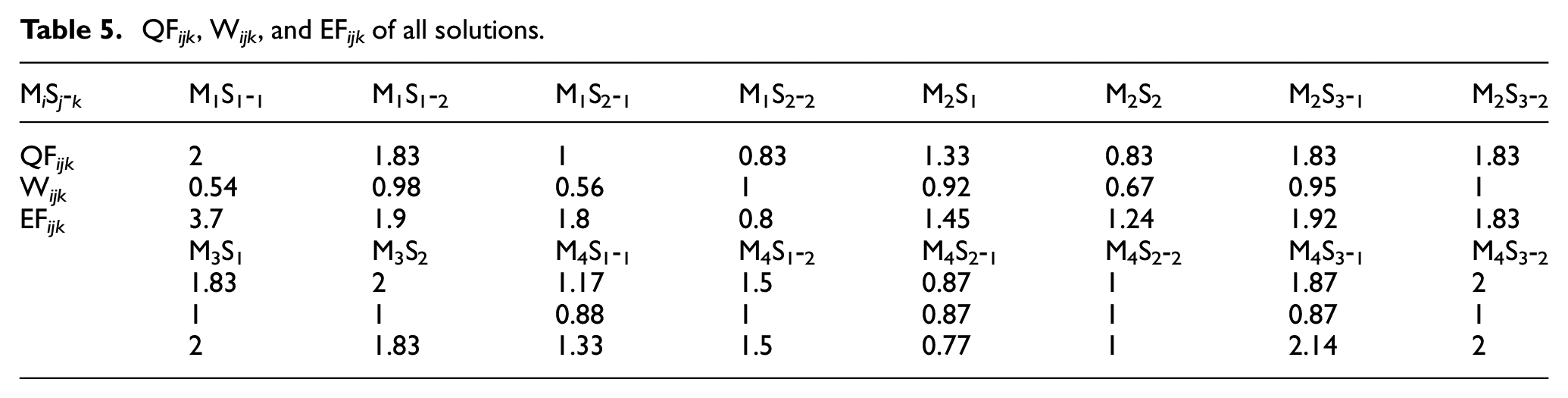
Values of QF ijk , W ijk , and EF ijk of all solutions are listed in Table 5. Despite the group of M1S1-1, M2S3- j , M3S1, and M4S3-2 which have the highest QF value are the best assurance ability of processing function, the group of M1S1-1, M2S3-1, M3S1-1, and M4S3-1which have the highest EF value are selected considering both processing function and light weight. M1S1-1, M2S3-1, and M3S1-1 can meet both the best functional satisfaction and the lightest weight, but M4S3-1 isn’t the best solution in the global requirements II and IV (requirement II is the operation accessibility during debugging; requirement IV is avoiding interference and collision among moving components). However, M4S3-1 is a set of binocular cameras, which do not need debugging after initial calibration. In addition, during the drilling and riveting process, other modules will block the view of M4S3-1, but the detection process of M4 has been completed. Therefore, M4S3-1 can still meet the processing requirements of products. The optimal structure consists of M1S1-1, M2S3-1, M3S1-1, and M4S3-1 of the end-effector is shown in Figure 6. As receiving the drilling signal, the pressing module of the end-effector is pushed out to apply predetermined pressure on the skin. Then the spindle of the drilling module is driven by AC servo motor and moves forward, and the swarf suction device starts up after the drill reaches the machining zero point. When the tool reaches specified depth, the spindle stops rotating and retracts quickly, and then the pressure foot is driven back by cylinders. If the end-effector receives the riveting signal, an appropriate rivet is sent to the riveting module and then the integrated riveter is pushed forward. After inserting rivets and riveting, the riveter is driven back by the cylinder. Following this step, the end-effector is driven by the machine tool to reach the next site and repeats above drilling-riveting operations.
QF ijk , W ijk , and EF ijk of all solutions.
Structure of the entire end-effector.
Positioning error coordinates variation and processing parameters
In order to obtain accurate positioning information, this article carries on the following works. The starting points of X/Y/Z are set at the origin of coordinate system {S}, and rotation centers of A and B axis are O1 and O2 respectively, a simplified model as shown in Figure 7. Suppose that the system moves along X/Y/Z-axis by distances of
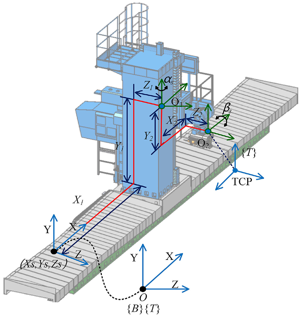
The simplified model of the machine tool.
wherein, x1, y1, z1, x2, y2, and z2 are link parameters of the machine tool.
and
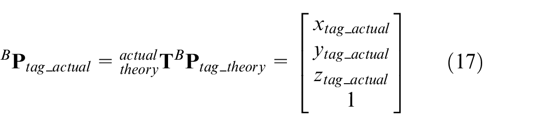
Practically, there is a deviation between the actual {Tag-i} and the theory {Tag-i} because of repeated clamping, environmental change, the local deformation of skins, and pre-processing error. The actual coordinate variation model is shown in Figure 8. Therefore, the theoretical coordinates of the tag point have to be transformed into the actual coordinates. The positioning benchmarks of products are scanned by the detection module of end-effector to calculate homogeneous transformation matrix
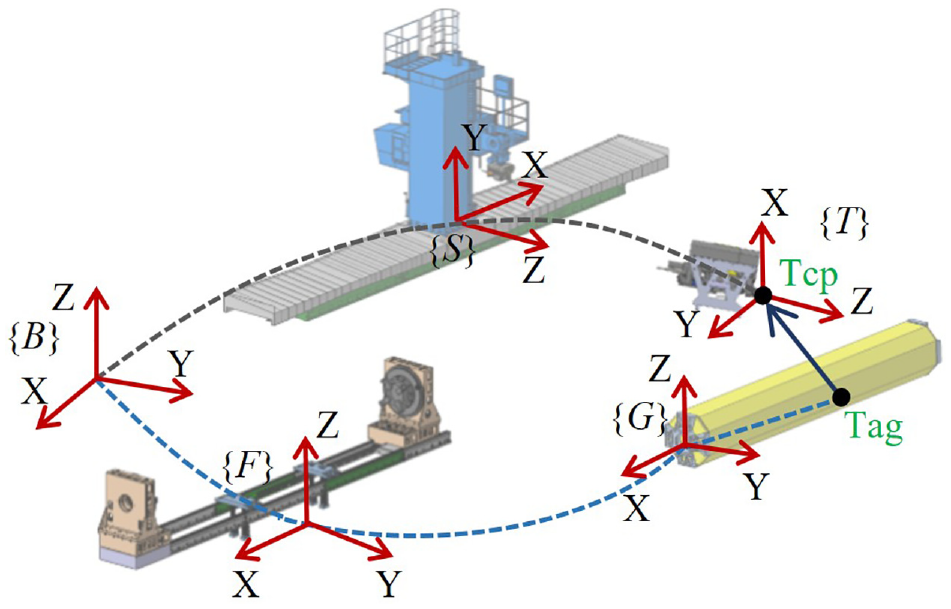
The actual coordinate variation model.
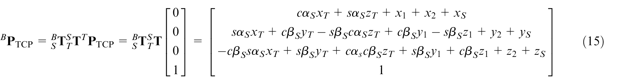
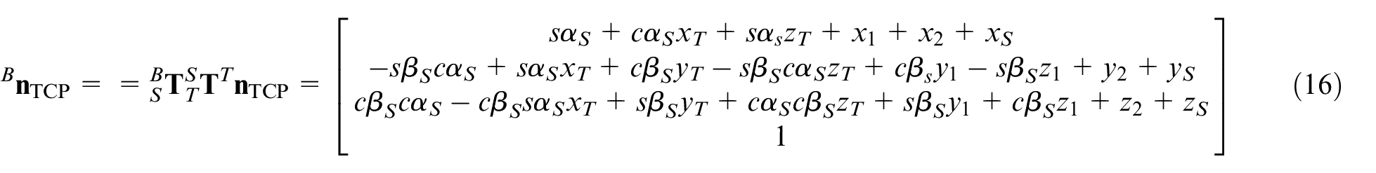
The theoretical coordinates in {B} of all tags are transformed into actual coordinates to guide the machine tool move until the TCP coincides with the actual tag point. Meanwhile, the actual normal unit vector
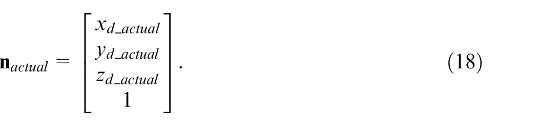
According to (11) and (12),
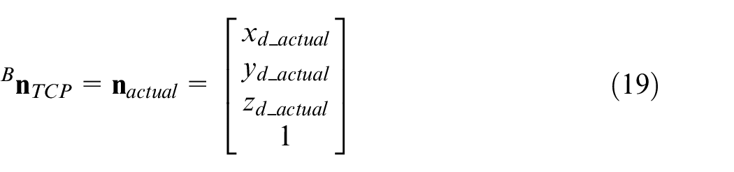
and
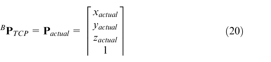
By substituting (15) and (16) into (19) and (20),
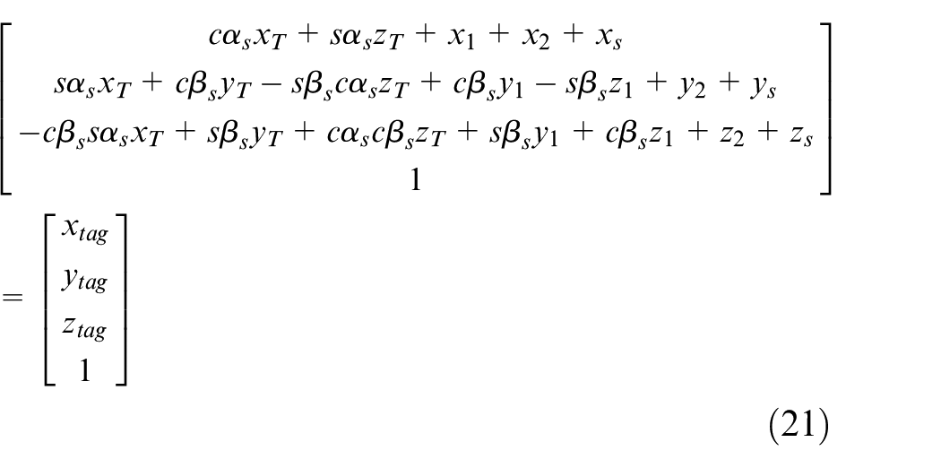
The actual positioning information
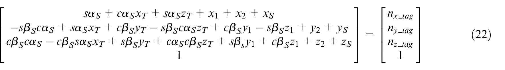
As for processing technology, rotational speed and feed rate are important controllable processing parameters in drilling. The selection of processing parameters is directly related to the workpiece material. The drilling quality of metal materials is observed through shapes of swarf and burr. The increasing feed rate is beneficial to the accuracy of holes aperture. However, a high feed rate raises the risk of tool twining, which aggravates the alloy hole wall roughness, causes wear of the drilling tool and even ultimately leads to process termination. Additionally, contact surface clearance is a major risk factor of interlayer burr height as drilling in stacked metal materials plates. Thus, drilling alloy holes have to adopt reasonable processing parameters including moderate rotary speed and moderate feed rate which can be determined by processing test, and a vacuum swarf conveyor is added to suck away swarf in drilling. Besides, the end-effector is equipped with the pressing foot to clamp upon the skin surface, thereby the gap between skin and frame is eliminated by pressing force. The effect of pressing force is shown in Figure 9. According to the advanced equipment in Europe and America, the actual pressing force is in the range of 300–1000 N.
The effect of pressing foot: (a) drilling without pressing force and (b) drilling with pressing force.
Experiment of functional verification
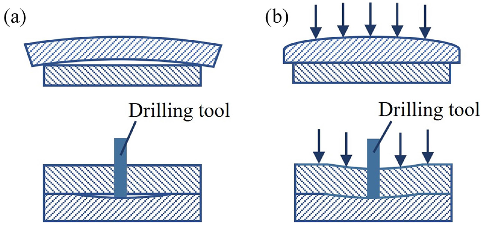
To illustrate the practicability of proposed methods and results in the above sections, the automatic drilling-riveting machine tool system is built as shown in Figure 10. A series of tests are carried out as follows. The platform and effects of tests are shown in Figure 11.
The automatic drilling-riveting machine tool system: (a) the drilling and riveting end-effector, (b) the single-column machine tool, (c) clamping and flipping fixture, and (d) support brackets.
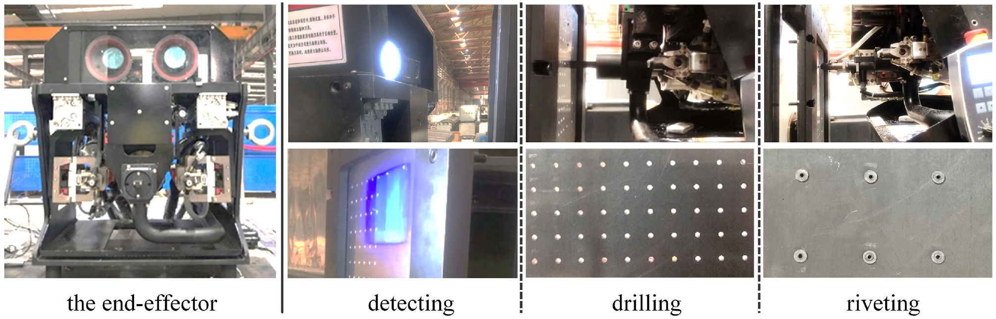
Test platform and test effect.
Firstly, a drilling test is conducted to verify the processing function and determine suitable processing parameters. Holes of 4 mm are drilled in a duralumin plate with 3 mm thick. A group of speeds and feed rates are given based on previous experience. Analyzing tests process records, stronger processing noise and vibration occur with feed below 2 mm/s, which will seriously affect the wall roughness of holes. However, while the feed is higher than 5 mm/s, tools are twined by swarf frequently, as shown in Figure 12. Additionally, an inside micrometer with accuracy of 0.001 mm was used to measure aperture data, and aperture error is less than 30 μm. According to ISO standard, the accuracy reached H9 (0–30 μm). The trend in Figure 13 reveals that the aperture deviation decreases with the increase in rotational speed initially, and the accuracy of holes aperture appears to be stable and aperture error is less than 12.5 μm when the rotational speed exceeds 5000 r/min. Yet it is worth noting that the risk of sticking tools cuttings increases as the rotational speed is too high. In conclusion, 4500–8500 r/min and 3–5 mm/s are chosen as optional ranges of processing parameters to ensure the stability of processing and the accuracy reached H8 (0–18 μm).
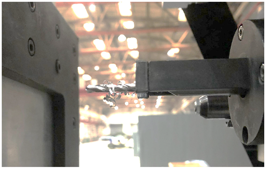
Tool twining by swarf.
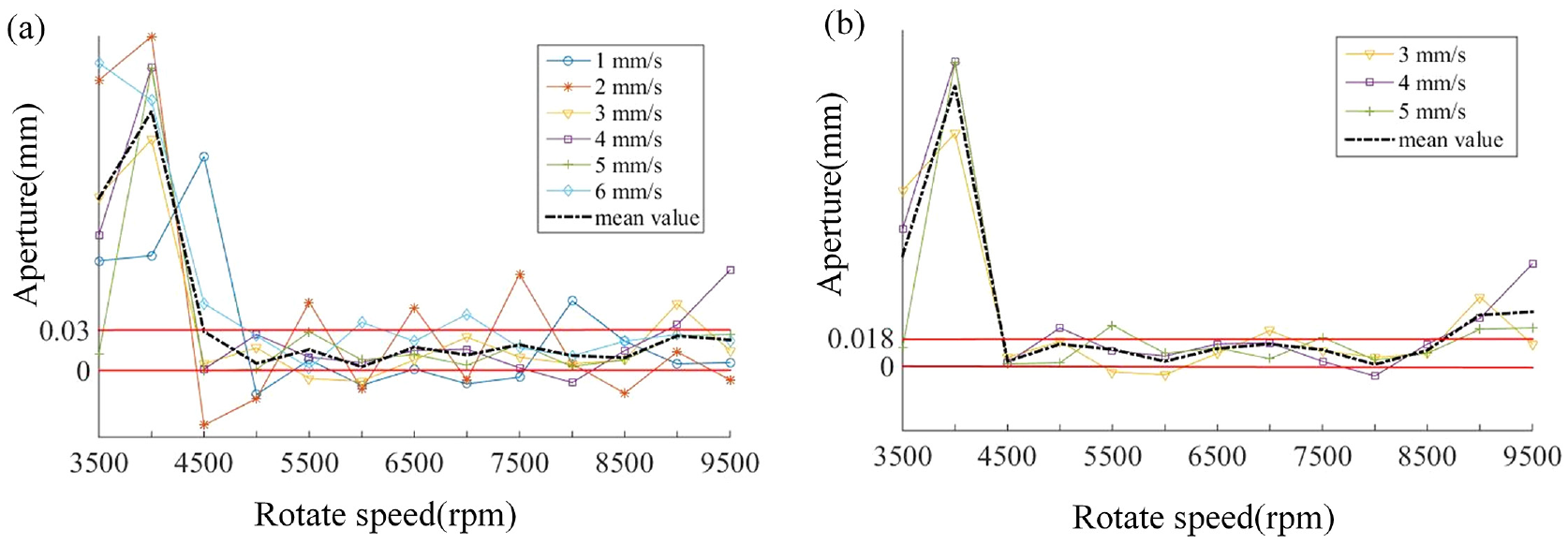
Trend of the aperture deviation with change in rotational speed (a) 3500–9500 r/min and 1–6 mm/s are chosen and (b) 4500–8500 r/min and 3–5 mm/s are chosen.
Subsequently, a riveting test is conducted. 3 × 2 holes with 30 mm intervals are drilled, and a micrometer caliper with a precision of 0.001 mm was used to measure the position of holes in workpiece coordinate system {G}, and the maximum X/Y error and position error are measured as 0.058 mm and 0.082 mm. Compared with the position error with 0.14 mm of other similar systems, the position error is reduced by 41.42%. The end-effector detects the holes drilled above in order to send coordinates and normal unit vector back to IPC, so that the end-effector can be adjusted to the right posture. The detection interface is shown in Figure 14. According to the aperture information, a rivet with the corresponding size is chosen, inserted accurately, and riveted by the riveting module. The result shows that assembly process is feasible, as shown in Figure 11. Then, a contrast experiment was conducted to verify the effect of detection and adjustment on riveting quality after secondary assembly of products. After the transformation of workpiece coordinate system, the first group of holes are riveted according to the coordinates and normal vectors recorded during drilling and the second group of holes are riveted after detection and adjustment. The results show that the rivets specifications are all correct, but the first group has inaccurate rivets insertion, as shown in the Figure 15(a). In the second group, the rivet heads on the surface are neat and uniform without defects such as skew, bump and crack, as shown in the Figure 15(b). The micrometer caliper was used to measure the height of rivets head, and the maximum errors of the two groups were 3 and 0.8 mm, respectively.
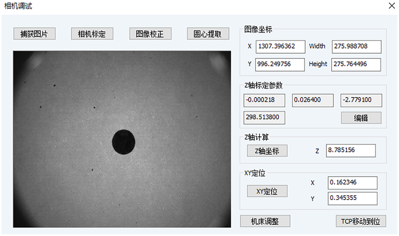
The detection interface.
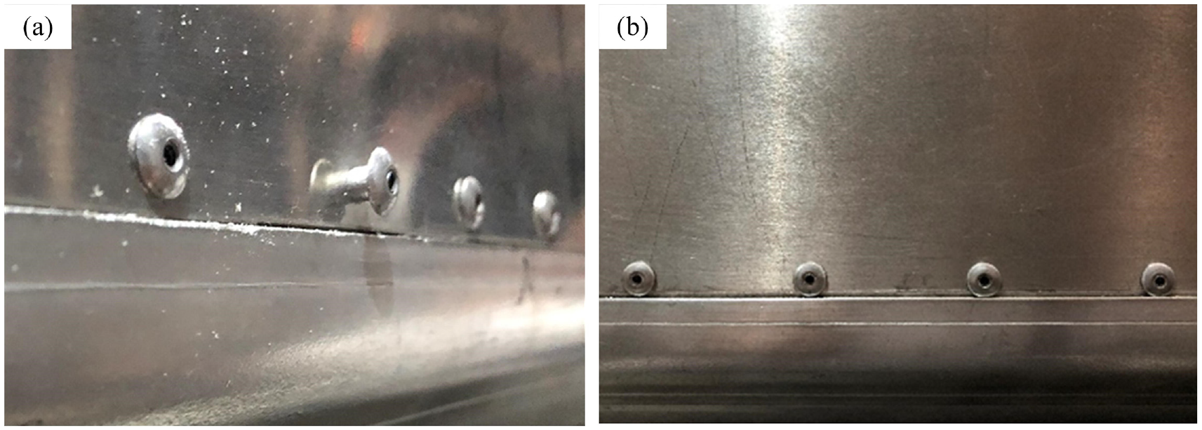
The effect of detection and adjustment: (a) the first group with inaccurate rivets insertion and (b) the second group without defects.
Then, another control test is carried out to verify the effect of pressing force as follows. Two groups of holes are drilled in a double-layer duralumin plate with the same processing parameters. The pressing force did not applied in one group, and the pressing force of the other group is set to 500 N during drilling. As holes are drilled without pressure, the interlaminar burr is obvious. But the interlaminar burr is not visible when the pressing force is applied during drilling. The contrast of interlaminar burr is shown in Figure 16(a) and (b), and the test result shows that the pressing force has a good inhibition effect on inter-laminar burr.
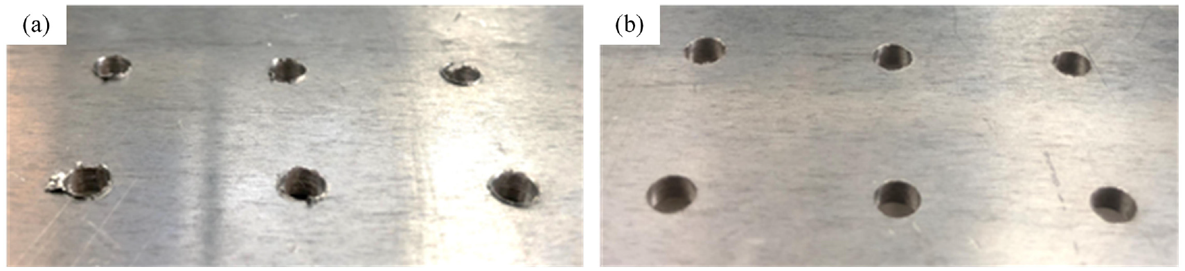
The contrast of interlaminar burr: (a) interlaminar burr without pressing force and (b) interlaminar burr with pressing force.
Finally, experimental verification is conducted on a sample workpiece of the aviation long box product. The workpiece is a 10-meter-long box with an octagon section, and processing flows are shown in Figure 17 as follows. The workpiece is loaded by hoisting firstly. Second, skins are pre-connected manually after clamped and supported by the fixture system. Finally, the machine tool is driven to drill and rivet on the workpiece which can be flipped to realize the processing task of all sides. The detailed drilling and riveting process is as follows: firstly, the reference points are scanned by the detection module to realize the transformation of workpiece coordinate system, and holes are drilled according to the preset NC program. Then the skins are removed manually for coating adhesive and pre-connect again. Finally, the holes are scanned to correct the coordinates and normal vectors recorded during drilling, and then riveted. In this paper, the experiment is implemented in two skins of the workpiece. As shown in Figure 18(a) and (b), the accuracy of holes aperture can reach H8, and the apparent quality of riveted joints is satisfactory. Furthermore, the efficiency can realize as fast as six holes drilling and eight rivets riveting per minute. The result of this experiment shows that the system has the ability to drill and rivet continuously based on ensuring quality.
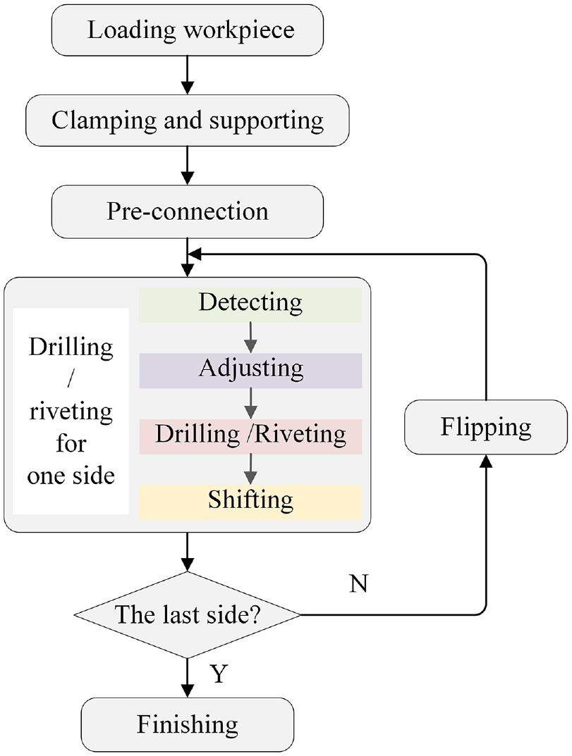
The processing flows of workpiece assembling.
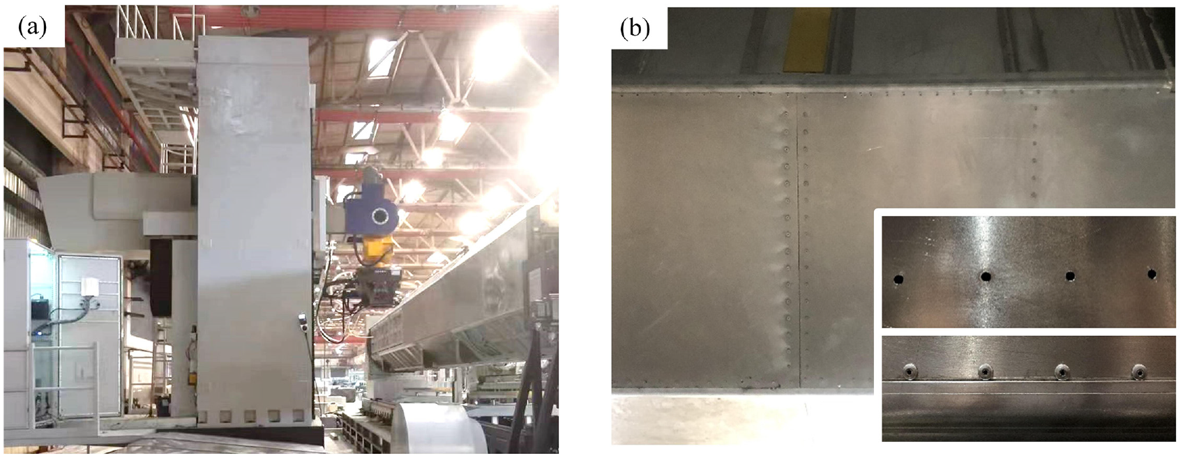
Experiments of the automatic drilling-riveting machine tool system: (a) the experiment platform (b) the drilling and riveting effect.
Conclusion
In this paper, the automation drilling-riveting machine tool assembly system building technique is discussed. And some research conclusions are obtained as follows.
A structural conceptual design method is proposed considering both efficiency and quality. This method can perform quantitative computation and qualitative analysis of the interaction between the assurance ability of processing functions and the weight of mechanical structures.
An automation drilling-riveting machine tool assembly system is developed for aviation long box products of which length from 6500 to 11,000 mm assembly. The system includes a single-column machine, assembly fixture, and light-weight end-effector, ensuring stability, accessibility, and efficiency, respectively. And the positioning error coordinates variation model is built.
After reasonable processing parameters are determined based on a series of tests, the experiment is conducted on the aero-structures drilling-riveting machine tool system. The result shows that the processing including fixing, flipping, detecting, drilling, and riveting can be implemented steadily and continuously.
Compared with the position error of other similar systems, the position error with 0.082 mm is reduced by 41.42%, the aperture precision can reach H8, and the rivets head height error ≤0.8 mm. Drilling and riveting efficiency can reach 6/min and 8/min. So the feasibility and effectiveness of this paper are fully proved.
The result indicates that the approach of the automatic drilling-riveting machine tool system development proposed in this paper is proved to meet the requirement of the assembly, and it can also be extended to deal with other aero-structures assembly to shorten the equipment design cycle, then speed the time of assembling through load reduction and satisfactory accuracies. Moreover, some technique challenges still exist. To further improve the building technical of the automatic assembling system, ongoing work can be focused on highly integrated, intelligent, all-digital, functional expansion, and energy conservation.
Footnotes
Declaration of conflicting interests
The author(s) declared no potential conflicts of interest with respect to the research, authorship, and/or publication of this article.
Funding
The author(s) disclosed receipt of the following financial support for the research, authorship, and/or publication of this article: The work reported herein is financially supported by National Natural Science Foundation of China (Grant No. 51875287 and 52005259), and The National Key Research and Development Program of China (Grant No. 2019YFB1310101 and 2019YFB1707403). Moreover, the authors would like to acknowledge the editors and the anonymous reviewers for their insightful comments.