
Abstract
Hot-rolled Al-Si alloy sheets are used to be formed Al alloy welding additions and cladding materials that are widely used in the aviation, automotive, and air conditioning industries. However, if parameters of hot-rolling process are not properly selected, porosity defects during casting will lead to cracks or fractures in Al-Si alloy sheets. This study based on meso-damage theory and established a damage equation describing porosity defects in the hot rolling process. The parameters of GTN (Gurson-Tvergaard-Needleman) void defect evolution, including the volume fraction of voids in different periods, the plastic equivalent variation of void nucleation, the standard variance of equivalent variation of void nucleation, and the correction coefficient of the material, are determined in this study. A finite element model of the porosity defects is developed based on the determined parameters. The finite element method is used to analyze the effect of different process parameters on the porosity defects and cracks in Al-Si alloy sheets during hot rolling, then we performed the hot rolling test to validate the results. The results show that the void stress and diameter are reduced and the quality of porosity defects is improved by decreasing rolling reductions and increasing the temperature. The optimized process parameters were a 20% depression and a temperature of 550°C.
Introduction
4004Al-Si alloy which uses silicon as the main alloying element exhibits good properties and is widely used in the automotive and air conditioning industries 1–7; it is also widely used in the aluminum foil manufacturing industry due to its advantages of good fluidity and low melting point. However, the high silicon content in the 4004 Al-Si alloy reduces the plastic deformation ability of the material,8,9 results in defects such as porosity and loosening during casting, and these defects are magnified during the rolling process. Thus, the mechanical properties of the alloy are reduced, and the quality and safety of the products are affected. But this problem cannot be effectively solved in the current production.
Some scholars have investigated machining and rolling via finite element analysis. Byon et al. 10 used finite element software to simulate the cold rolling process of steel strips, predicted the length and direction of strip edge crack extension with the ductile fracture criterion, and performed cold plate rolling test to validate the reliability of finite element analysis. The result shows that using a concave profile which corresponds to a negative roll can reduce the occurrence of edge cracks in the strip during cold rolling. Kumar et al. 11 used the finite element software Deform-3D to investigate the roll bite deformation during rolling of microalloyed and plain carbon steels, discussed the effects of temperature and friction coefficient and performed rolling test. It was found that the peak stress of microalloyed steel was 13%–25% higher than ordinary carbon steel during roll bite. Huang et al. 12 used ABAQUS to conduct a finite element simulation of a 7050 Al alloy superthick plate to analyze the equivalent strain and the rolling force after asynchronous rolling. The result shows that the change of strain with temperature is not significant, but the decreasing trend of rolling force is significant with increasing temperature. Komori 13 proposed a combined method of simulating sheet bending with rigid-plasticity finite elements and analyzing sheet buckling with the basic theory of buckling. It was found that the amount of bending at the back end of the plate was consistent with the theoretical analysis by a hot plate rolling simulation. In summary, many significant results on the application of finite elements in rolling have been achieved. The primary focus of research was to simulate rolling processes with different finite element softwares, then to analyze the influence of various process parameters on the stress–strain relationship and materials’ changes about internal structure and organizational performance during rolling.14–16 However, researches on the porosity defects of Al-Si alloys have been relatively scarce.
In this paper, we use numerical simulation method of finite element software ANSYS and applies elastoplastic finite element theory to the hot rolling process with porosity defects in aluminum-silicon alloy to study the effect of different rolling process parameters (temperature, rolling reduction) on porosity defects. These process parameters seriously affect the quality of the finished product, and by applying elastoplastic finite element theory to the hot rolling process with porosity defects in Al-Si alloy.
Determination of damage parameters and rolling finite element modeling
Determination of damage parameters for the GTN model
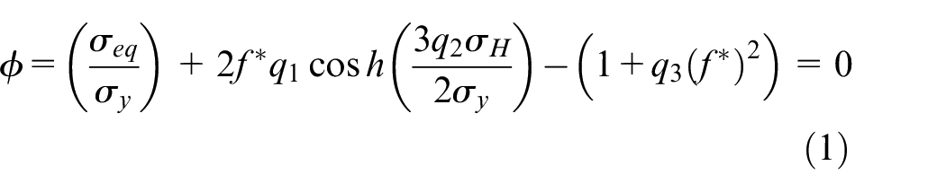
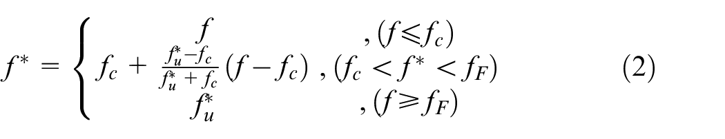
During production and processing, the impact of void defects inside a material is ignored in most cases, which often lead to a gap between the mechanical properties of the finished product and theoretical data.17–20 The damage inside a material was considered in GTN meso-damage model. Every parameter of the model has physical significance, which genuinely reflects the damage mechanism of the material. It is the necessary condition for accurate simulation of the damage model to define parameters.21–25 The GTN damage model is presented in equations (1) and (2).
The GTN damage model contains many damage parameters.
The volume fraction of voids is determined by measuring the area ratio in the microstructure of an Al-Si alloy at different stages of the rolling process: the original stage, the stage when cracks appear, and the stage when complete fracture occurs. The measurement of the area ratio is given in Figure 1.
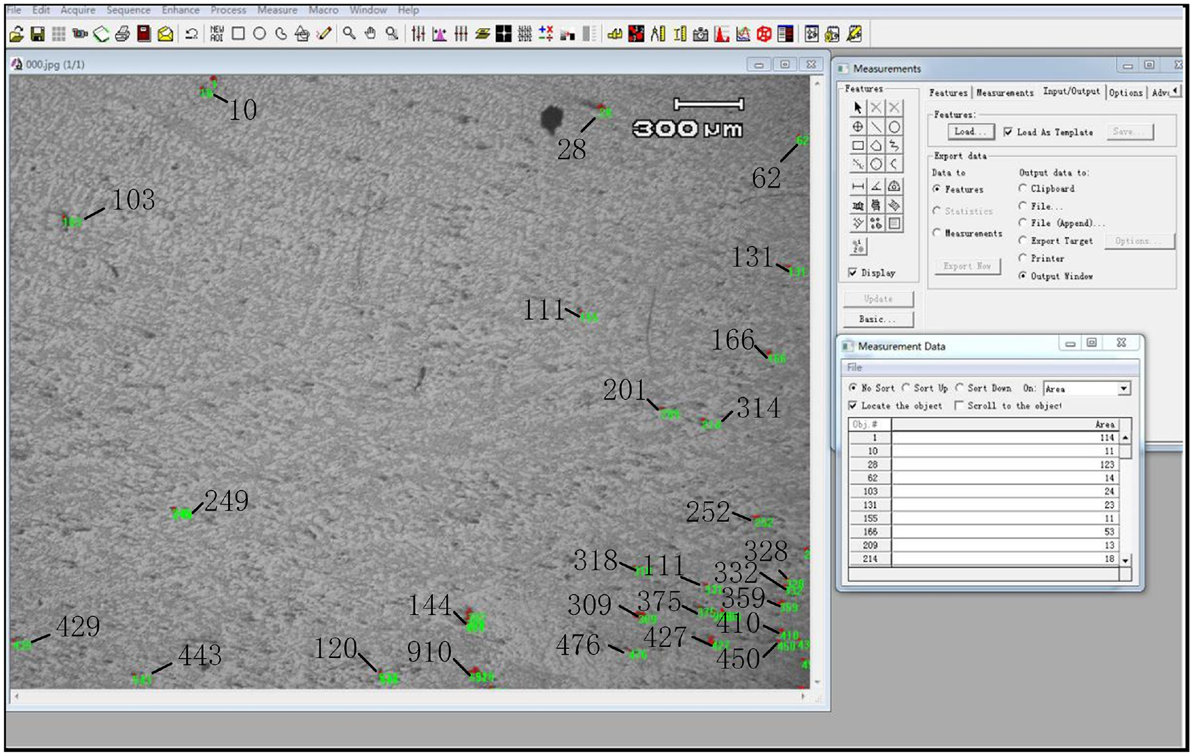
Volume fraction measurement.
The GTN damage model parameters were finally determined as following:
Finite element modeling
In this paper, based on the GTN meso-damage model, we use ANSYS finite element analysis software to numerically simulate the change of porosity defects during the 4004 Al-Si alloy rolling process. Nonlinear explicit dynamics was used in the rolling process. Diameters and rolling speed of both the upper and lower rolls are same. Both rolls are active and considered rigid rolls which means roll bending and flattening are ignored in the simulation. The following parameters were used: roll diameter is 200 mm, roll length is 280 mm, and friction coefficient is 0.3. The dimensions of plates are 90 mm length, 30 mm width, and 20 mm height. The rolling finite element model is shown in Figure 2. To study the evolution of voids at different locations and with different sizes, five void models are established inside the rolled plate. The void locations and dividing mesh are shown in Figure 3. The void sizes are given in Table 1.
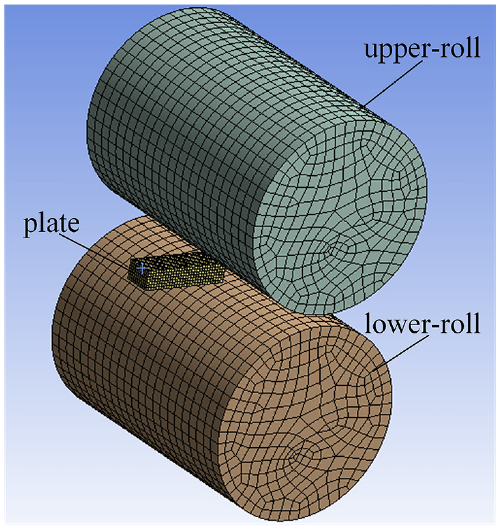
Rolling finite element model.
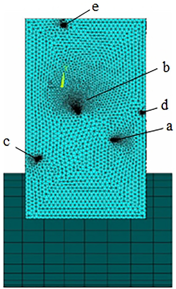
Location of voids.
Gas porosity sizes.
Simulation of process parameters on porosity defects
Numerical simulation of depression parameters
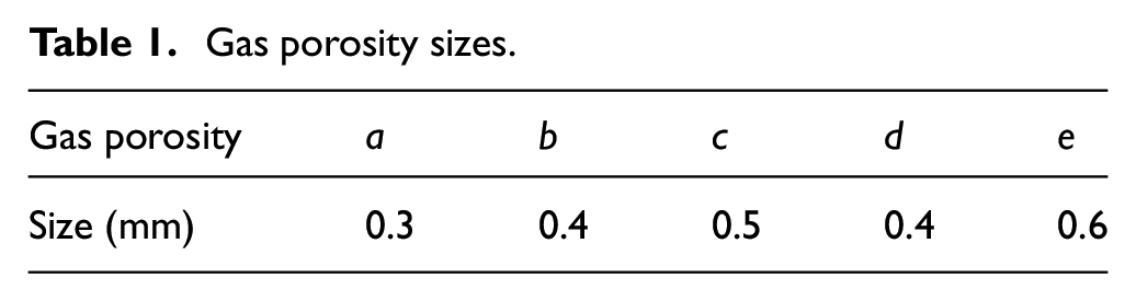
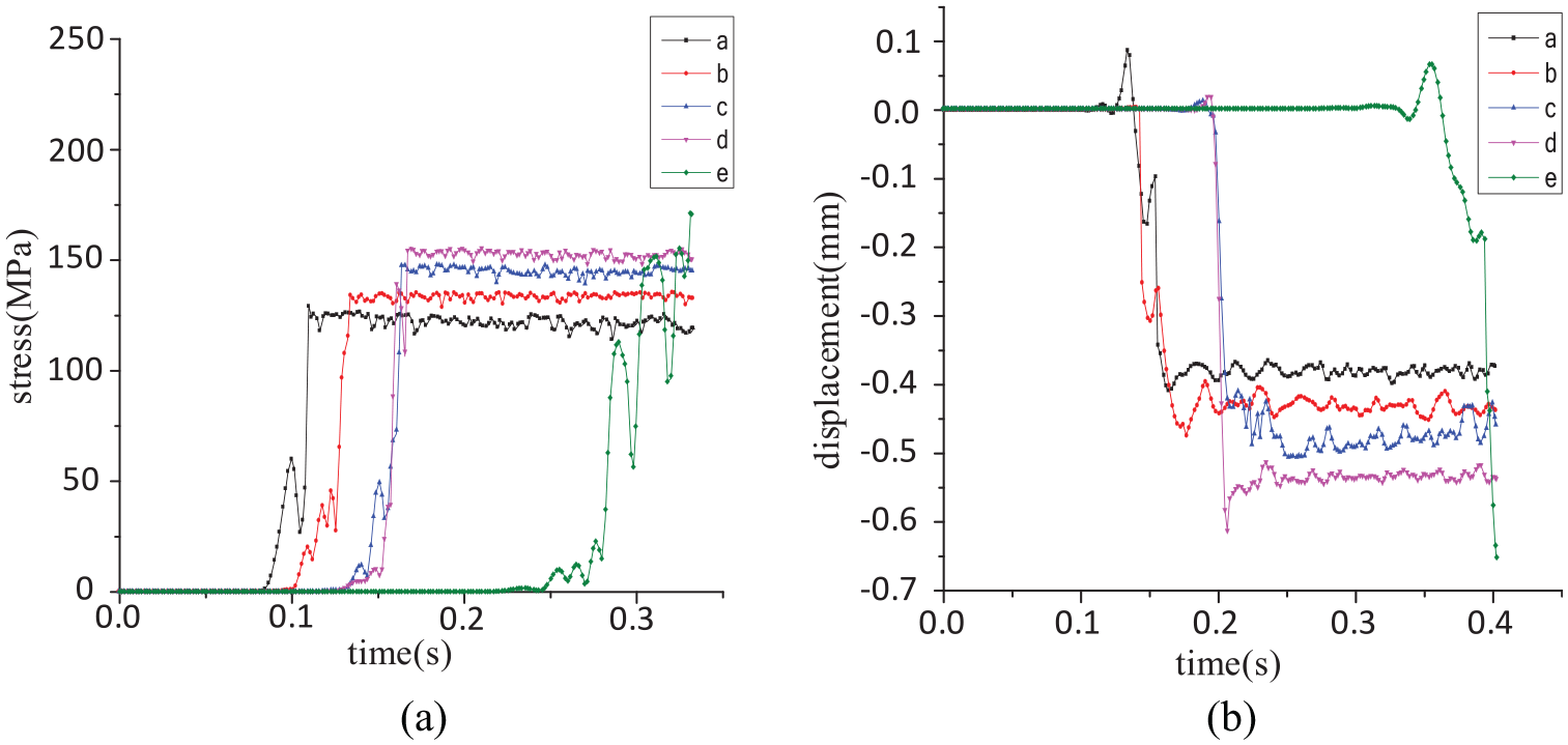
The choice of rolling reduction has a significant impact on the shape and quality of the rolled product. Thus, to guarantee the quality of the rolled product, a suitable rolling reduction should be selected. If the rolling reduction is too heavy, the requirements of the rolling equipment will be very high. Moreover, a too significant rolling reduction will lead to that the plate easily generate excessive local deformation and cracked edges, broken strips, and other failure modes. If the rolling reduction is too small, the number of rolling passes will increase and productivity will decrease. In addition, it is impossible to achieve satisfactory rolling results because of the decrease in the contact surface. Numerical simulation at 550°C was chosen to calculate the effect of different rolling reductions on porosity defects. Graphs a and b in Figure 4 show the stress and the size variation of voids versus when the rolling reduction is 30%.
Stress and dimensional changes in voids measured at 30% rolling reduction: (a) stress analysis diagram of the air voids and (b) void size analysis diagram.
As shown in Figure 4, the stress of voids (c, d, e) at the edges of the plate is higher than the stress of voids (a, b) inside the plate. The main reason of this finding is that during the rolling process, the voids inside the plate are subjected to compressive stress. With the action of compressive, elastic deformation of the material is converted into plastic deformation, resulting in internal convergence of the voids, and voids will be filled. At this time, the stress increases, then decreases slightly, and then stabilizes. At the same time, the same trend can be observed in the dimensional change of voids. In addition, the changes of the stress and dimensions around the larger voids (c, e) are more significant than those around the slightly smaller voids within the plate. As a special body inside the material, the existence of large-volume voids enhances the deformation ability of the surrounding material under the condition of the same reduction. With the increase of rolling force, the deformation ability of the material around the large holes is relatively strong, but at the same time, the existence of voids reduces the bearing resistance of the material. This makes the material deformation around the large holes be greater and the stress intensity be also higher under the constant rolling reduction.
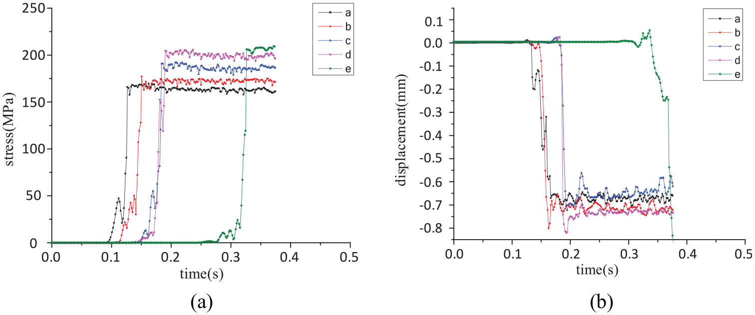
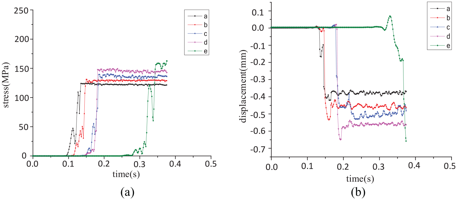
Figure 5 shows the stress and size variation curves of the voids at 20% rolling reduction. It can be found that as the rolling reduction decreases, the variations of stress and size about the voids decrease. The main reason is that as the rolling reduction decreases, the degree of material deformation from elastic to plastic deformation decreases. At first, the stress rapidly increases, then undergoes small fluctuates with small range and finally becomes stable. As the loads around the voids decrease, the holes’ ability to increase the deformation of the surrounding material decreases, and the void is subjected to less stress, resulting in a reduction of deformation.
Stress and dimensional changes in voids measured at 20% rolling reduction: (a) stress analysis diagram of the air voids and (b) void size analysis diagram.
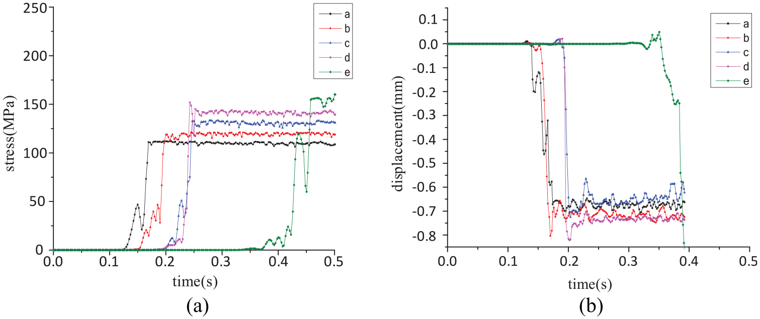
Figure 6 shows curves which describe the changes of stress and sizes for voids with a 15% rolling reduction. As seen by comparing Figures 4 to 6, as the rolling reduction decreases, the overall stress of the plate decreases, and the stress near the voids improves significantly. It can be concluded that as the rolling reduction decreases, there is a more significant improvement about the overall plate stress and porosity defects during the rolling process. The reason of this phenomenon is that because as the rolling reduction decreases, the stress mutation around the holes become less pronounced. The material’s yield strength increases with the combination of the rolling force and the pressure around the voids. The deformation of the holes is sufficient by itself to withstand the energy release without adding deformation to the surrounding material. Reducing the rolling reduction effectively prevents cracking of the material during rolling. Therefore, during the rolling process, we should choose a minor rolling reduction under the premise of ensuring efficiency.
Stress and dimensional changes in voids measured at 15% rolling reduction: (a) stress analysis diagram of the air voids and (b) void size analysis diagram.
Numerical simulation of the effect of temperature on void
During the Al-Si alloy rolling process, the energy between the rolling plate and the rolls is converted from friction into heat, when the rolling plate under pressure produces plastic deformation. Furthermore, the rolling plate, rolls, and surrounding media (air and coolant) transfer heat, which resulting in a very complex temperature change during the rolling process of Al-Si alloy. The temperature gradient of the porosity defects has a significant effect on the stresses, strains, and flow stresses, which further affects the mechanical properties of the formed aluminum sheet. After intense plastic deformation, the thermal boundary conditions imposed on the rolled plate unit also change, resulting in a change in the distribution of the temperature field. Thus, the rolling process of Al-Si alloys is a nonlinear thermal analysis problem.
This paper is based on ANSYS finite element analysis software to simulate the variation in porosity defects at three different temperatures (400°C, 500°C, and 550°C) within the temperature range suitable for rolling Al-Si alloys.
Figure 7 shows the stress analysis curve graph and size change curve of the void at 400°C. The stress analysis curve shows that the stress around the voids increases rapidly with time in the initial stage of plastic deformation, and this stage is dominated by the hardening phenomenon. With a further change in plastic deformation, the dynamic softening effect increases, which gradually offsets the hardening phenomenon. The rate of stress increase gradually decreases, which is reflected in the curve that the amplitude of the curve rise decreases.
Stress and dimensional changes in voids at 400°C: (a) stress analysis diagram of the air voids and (b) void size analysis diagram.
Figure 8 shows the stress analysis curve and dimensional change curve of the voids at 500°C. The stress curve shows a similar pattern to that at 400°C, but the stress value near the voids is significantly reduced. The reason for this phenomenon is the effect of temperature on the deformation resistance: as the temperature increases, the kinetic energy of the aluminum atoms inside the rolled plate becomes more extensive, and the vibration amplitude of the aluminum atoms increases. Therefore, the coordination between the grains improves, which makes it easier for the aluminum sheet to deform, for dynamic deformation, and recrystallization to occur, and for defects around the voids to be improved.
Stress and dimensional changes in voids at 500°C: (a) stress analysis diagram of the air voids and (b) void size analysis diagram.
Figure 9 shows the stress analysis graph and size change curve of the voids at 550°C. A comparison of the stress analysis graphs at 400°C, 500°C, and 550°C shows that as the temperature increases again, the stress around the voids decreases, and the size changes of the voids are small. We can conclude that as the temperature increases, the improvement of porosity defects becomes more pronounced during the rolling process.
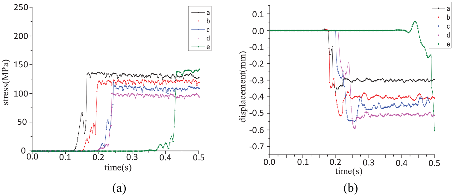
Stress and dimensional changes in voids at 550°C: (a) stress analysis diagram of the air voids and (b) void size analysis diagram.
Experimental validations
Experimental specimens and experimental procedures
For this rolling experiment, 4004 Al-Si alloy plates were used. The specimens were prepared by casting the Al-Si alloy, cutting the Al-Si alloy steel plates, and other processes.
The casting of the Al-Si alloy plates involved preheating in a crucible resistance furnace, heating the aluminum block in the crucible to a molten state (700°C) for 30 min, adding Si and other elements and stirring, injecting the metal into the already preheated mold after cooling and removing the specimen.
The heating rate and rolling mill required to ensure consistent specimen dimensions and sufficient specimens for experimental verification are shown in Figure 10. The Al-Si alloy plates were cut on a sawing machine, and the final dimensions of the plate specimens were 90 mm × 30 mm × 20 mm. The cut specimens are shown in Figure 11(a). According to the experimental simulation scheme and different rolling methods, the marked numbered specimens were subjected to heating, rolling, annealing, and rerolling in sequence. The rolled plate specimens are shown in Figure 11(b). Postrolled samples were subjected to tensile tests to determine the mechanical properties of the finished rolling products under different process parameters. The rolled finished products were subjected to metallographic treatment, rubbing, polishing, and corrosion to observe the internal microstructure of each specimen after rolling.
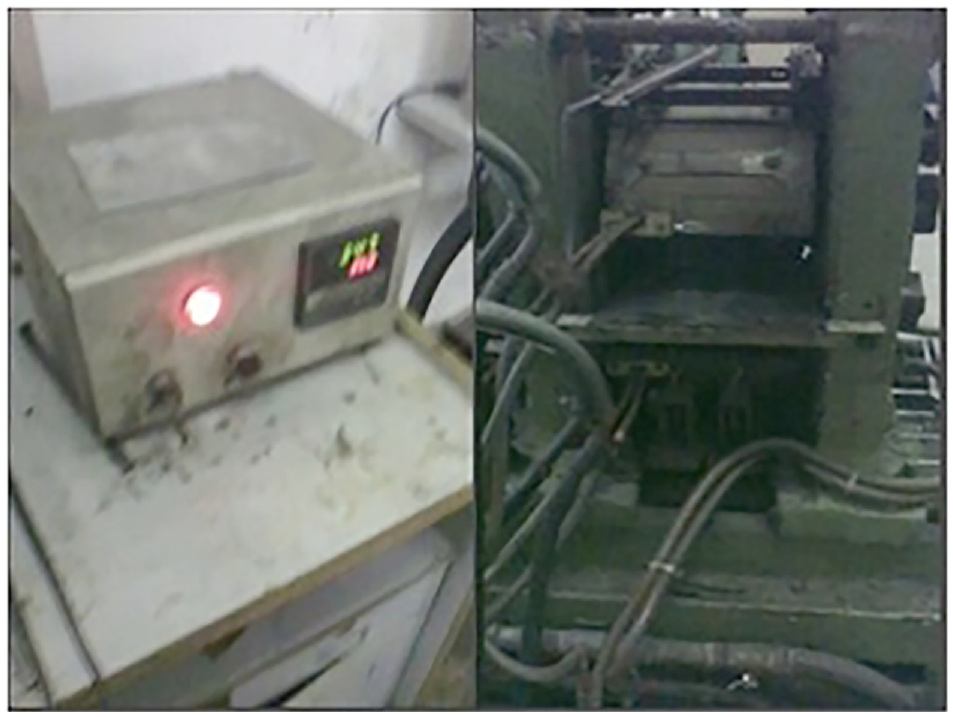
Heating furnace, rolling mill.
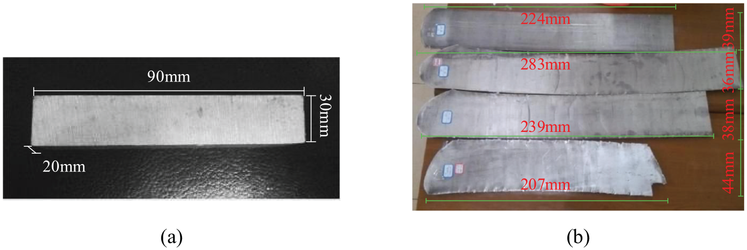
Al-Si alloy sheet before and after rolling: (a) before rolling and (b) after rolling.
Experimental verification of the effect of depression on void
To verify the accuracy of the numerical simulation results, rolling experiments were carried out on 4004 Al-Si alloy, and the same process parameters were selected as in the numerical simulation to observe the microstructure of the rolled sheet.
Metallographic diagrams of hot rolled 4004 Al-Si alloy plates with a 30% rolling reduction in each of the five passes are shown in Figure 12(a). The average void diameter of the plates after rolling was approximately 0.28 mm, and the tensile strength of the plates after rolling was approximately 169 MPa. Figure 12(b) shows the metallographic organization of the plates after rolling with a 20% rolling reduction over eight passes. The microstructure of plates exhibited a dynamic recrystallization pattern. The size of the voids decreased as the number of passes increased for the dynamic recrystallization phenomenon, with an average void diameter of approximately 0.17 mm and a tensile strength of approximately 188 MPa. Figure 12(c) shows the organization of Al-Si alloy plates with a 15% rolling reduction over 12 passes. As the number of rolling passes reached the maximum value of this experiment, the void diameter and grain area also decreased with a decrease in the rolling reduction, and the distribution also achieved maximum uniformity. The average diameter of voids was 0.16 mm, and the tensile strength reached 192 MPa.
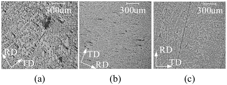
Metallographic organization of porosity at different pressures: (a) 30% depression,(b) 20% depression, and (c) 15% depression.
Through the multipass rolling test of casting 4004 Al-Si alloys with 30%, 20%, and 15% rolling reduction, the initial thickness of 20 mm was plastically deformed to approximately 5 mm by rolling. The volume and distribution of the voids inside the organization after rolling were studied, the mechanical properties of the specimens were tested, and reasonable pressing parameters were finally determined. As shown in Figure 13, the performance of a plate of the same thickness rolled with different pressures was compared with the simulation calculation results, and the accuracy of the results was verified according to the experiment. The results are that the size and stress of the voids decreased as the rolling reduction decreased.
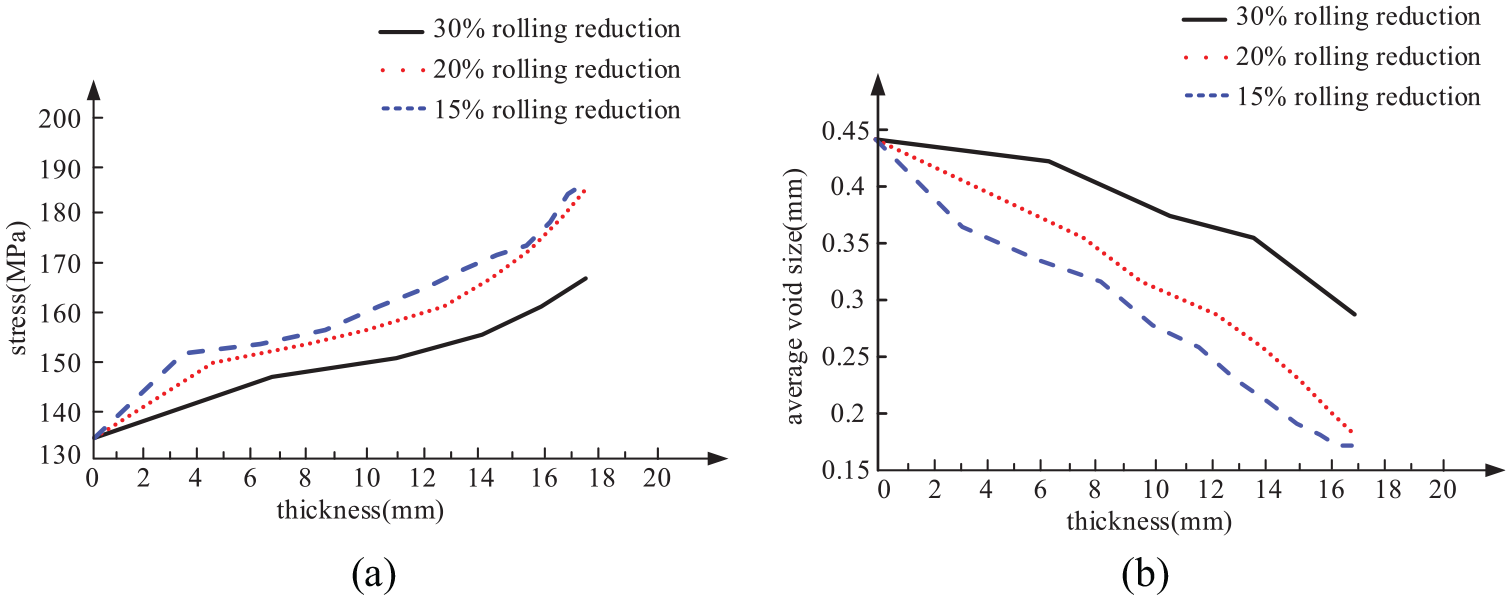
Sheet properties at different rolling reductions: (a) tensile strength analysis chart and (b) void size analysis diagram.
Experimental validation of the effect of temperature on void
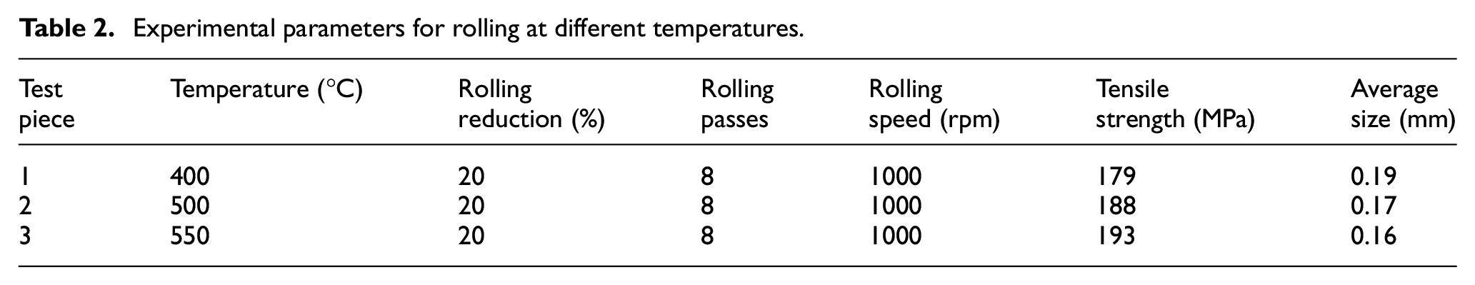
To verify the accuracy of the numerical simulation about the effect of temperature parameters on the voids, rolling experiments were carried out at different temperatures of numerical simulation. Figure 14(a) to (c) show the morphological changes in porosity after rolling at 400°C, 500°C, and 550°C, respectively. The metallographs show that as the temperature increases, the shape of the voids becomes increasingly regular, and the volume of voids significantly decreases. But the mechanical properties of the sheet improve significantly as the volume of the voids decreases. The experimental parameters for rolling at different temperatures are given in Table 2. Based on the average size of the voids measured after the experiments, it is also apparent that the size of the voids and the tensile strength of the plates become perfect as the temperature increases.
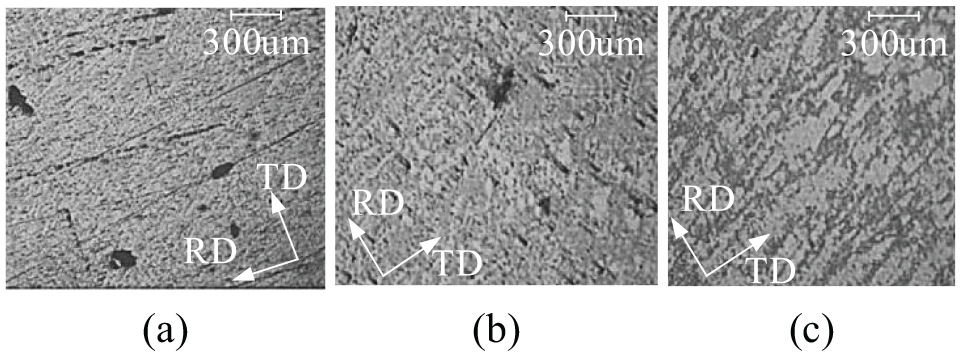
Metallographic organization of rolled plates at different temperature: (a) 400°C, (b) 500°C, and (c) 550°C.
Experimental parameters for rolling at different temperatures.
Conclusion
This paper establishes the damage equation for porosity defects, determines the parameters for the evolution of GTN porosity defects, and provides the initial parameters for the finite element model of porosity defects. Through numerical simulation and experimental verification, the influence of process parameters on the porosity defects is determined. A decrease in rolling reduction or an increase in temperature can decrease the stress and diameter of the void, which will improve the porosity defects and result in minor cracking of the Al-Si alloy during the hot rolling process. Considering practical production requirements, the best sheet properties and productivity are achieved by rolling at 20% reduction and a hot rolling temperature of 550°C.
Footnotes
Appendix
Declaration of conflicting interests
The author(s) declared no potential conflicts of interest with respect to the research, authorship, and/or publication of this article.
Funding
The author(s) disclosed receipt of the following financial support for the research, authorship, and/or publication of this article: Major science and technology projects of Heilongjiang Province (2019ZX10A01)