
Abstract
Precision grinding is a promising method for machining microstructured surfaces. Controlling microstructured surface geometries provides interesting insights into the optimisation of their usage based on the application fields. This requires an understanding of the effects of the factors influencing the grinding process. The effects of the designed process parameters on the geometries of microstructured surfaces machined using precision grinding is investigated herein. The investigated parameters include the velocity ratio between the workpiece feed rate and wheel cutting velocity, in addition to the grinding depth of cut. First, a mathematical model is developed to correlate the designed grinding parameters and the resultant geometry of the ground microstructured surfaces; furthermore, the geometrical parameters of the surface microstructures are defined. Subsequently, an algorithm and a simulation method are used to illustrate the change in the microstructure geometries with varying operating parameters. Subsequently, precision grinding experiments under various conditions are performed on the surfaces of TC4 titanium alloys for experimental investigations. The obtained microstructure geometries are analysed and compared with those predicted via simulation. The results confirmed the accuracy and ability of proposed strategy in designing and machining the microstructured surfaces with controlled geometry via precision grinding. Finally, the behaviour of the geometrical parameters of the microstructured surfaces based on the investigated operating parameters is discussed.
Introduction
In recent years, microstructured surfaces have been applied in advanced manufacturing to improve the performance of engineering surfaces. Compared with conventionally finished smoothed surfaces, microstructured surfaces allow numerous features capabilities to be created on them. For instance, the performance of bearing sliding surfaces is improved by employing microstructured surfaces.1–3 The extra-hydrodynamic pressure and trapping microscopic particles within the micro-dimples significantly reduces the wear and friction between the sliding surfaces. Meanwhile, the cooling effectiveness improves significantly under the same heated work conditions, and the adhesive resistance of cutting tools is promoted by the formation of micro/nanopatterns.4,5 The relationship among the method, functionality, and application fields of microstructured surfaces has been investigated to provide insights for solving various design issues.6–9 Applications of microstructured surfaces include grinding tools, 8 rings, 10 engine cylinder liners, 11 and optics. 12
The methods for manufacturing microstructured surfaces have been investigated in various studies.13–15 Recently, precision grinding has been extensively applied to achieve microstructured surfaces owing to its advantages. This method is simple, inexpensive, easy to operate, and fast. The structuring process constitutes the finishing operations and does not involve additional steps. Several shapes can be repetitively formed on ground surfaces. The wheel surface is reformed using a viable method to create shapes/grooves. 16 Subsequently, the intended surfaces are structured to a determined scale via these grooves during the grinding process. Different variables affect the final geometry of the surface microstructures, including the designed grooved wheel and the grinding conditions.
Therefore, surface structuring via grinding has been investigated numerically, theoretically, and experimentally. Stępień and Szafarczyk17,18 presented the machining of basic types of surface structures on flat surfaces via grinding. A grinding wheel was grooved using a single-point dressing tool, and the ground surface was reshaped to replicate the wheel grooves. A pair of critical limits for the velocity ratio was proposed to successfully machine the structures. Silva et al.19,20 developed a grooving method by connecting a dressing tool to an electro-mechanical exciter. While the wheel was rotating, the dressing depth changed, and grooves created on the wheel. Subsequently, the grooved wheel was operated at a selected velocity ratio to machine the structures on cylindrical surfaces. Silva et al. recommended a low-velocity ratio to machine surface structures at micro-scale sizes. Denkana et al.21,22 applied profile dressing and grinding processes to produce riblet structures on ground surfaces to decrease friction and wall turbulence. Xie et al. 23 investigated the grinding of micro pyramid-structured surfaces using a V-shaped tip diamond wheel under diverse conditions. An explanation of the error sources and methods for compensating them were provided. Recently, Monier et al. 24 investigated the machining of microstructured surfaces of advanced geometries via grinding. Several microstructure designs were illustrated by reshaping the grinding wheel into different geometric shapes.
Machining microstructured surfaces via grinding of controlled geometries is essential for maximising their benefits and optimising their functionalities. Most previous studies that have considered the kinematics of the grinding process aimed to generate surface structures or control their size. However, the effect of process kinematics on some parameters of the ground microstructures geometry is still unclear. In addition, the effects of the designed grinding depth on the geometrical parameters of the surface microstructures were not considered.
We previously developed a strategy for designing and machining surface microstructures using precision grinding. 25 In this study, the effects of the designed process parameters on the geometrical parameters of ground microstructured surfaces are investigated. The investigated parameters include the velocity ratio between the workpiece feed rate and the wheel cutting velocity, in addition to the grinding depth of cut. First, the geometrical parameters of the designed microstructured surface are defined. Subsequently, the mathematical model correlating the investigated process parameters and microstructural geometrical parameters is discussed. The changes in the geometry of the surface microstructures as a result of changing the process parameters are described. Precision grinding experiments are designed and then performed on the surfaces of TC4 titanium alloy samples to investigate the effects of the investigated parameters. The experiments show promising agreements and confirmed the reliability of the presented strategy for designing and fabricating microstructured surfaces via grinding.
Modelling of grooved wheel and workpiece with microstructured surface based on designed grinding condition
Figure 1 shows a schematic illustration of the geometric variables of the grooved wheel and the associated microstructured surface machined under the designed grinding conditions. Figure 1(a) shows the wheel surface of radius
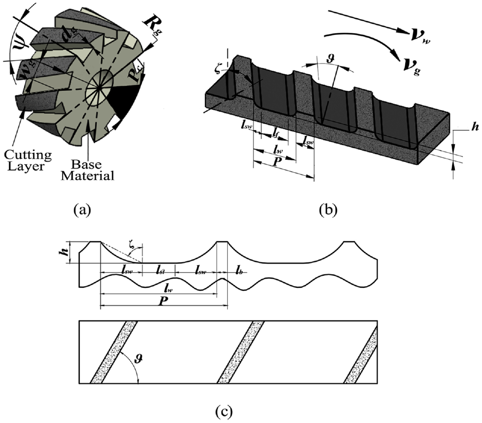
Schematic illustration of the (a) grooved wheel and (b) microstructured surface; (c) detailed definitions of the designed surface geometrical parameters.
A schematic illustration of the ground microstructured surface and its geometrical parameters shown in two dimensions are presented in Figure 1(b) and (c), respectively. The surface geometrical parameters are determined by the bearing width
Hence, the ground width

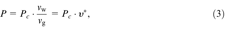
The pitch of the microstructures is expressed as follows:

The wheel circular pitch
Where
Subsequently, the value of the groove width

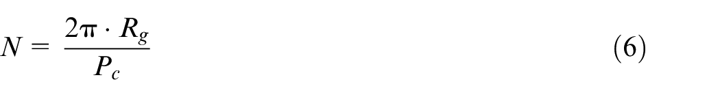
The number of wheel divisions,
The angle of the microstructures sidewall
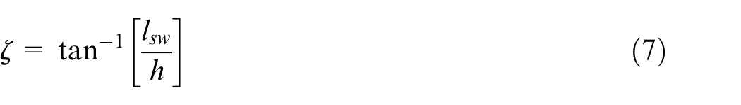
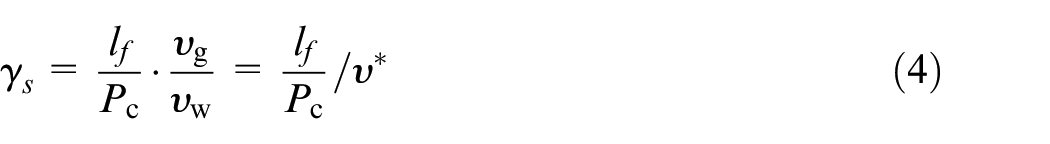
The slope angle
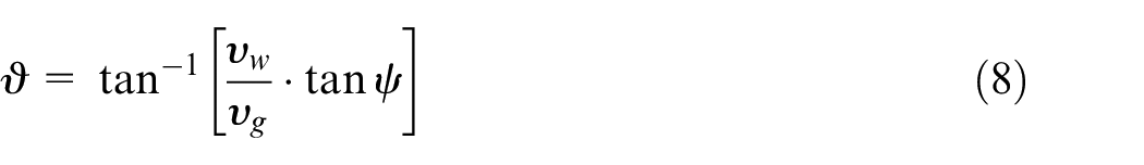
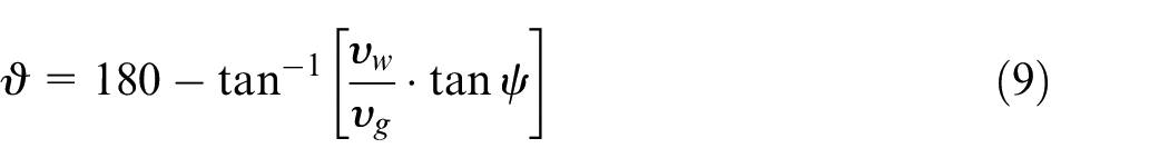
Meanwhile, slope angle
Effect of grinding condition on geometry of microstructured surface
In this section, the effects of the grinding condition on the surface microstructure geometry is investigated. Based on the presented mathematical model, an algorithm and kinematic simulation method are applied to illustrate the changes in the geometrical parameters of the surface microstructures, which are considered the output, due to the input designed grinding conditions. Figure 2 illustrates the flow chart diagram of the procedures implemented in the simulation method to generate the grooved wheel and the associated microstructured surface based on the designed grinding parameters. The spacing between the microstructures is estimated using the pitch values
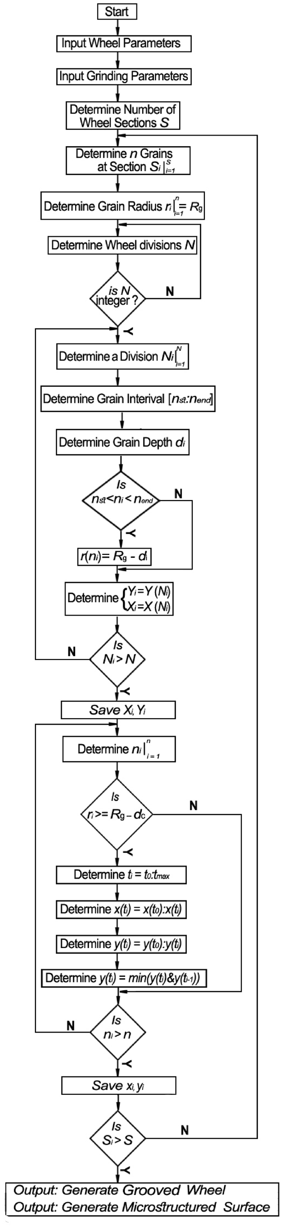
Flow diagram for generating simulation model of the grooved wheel and microstructured surface.
Effect of operating velocity ratio on geometry of microstructured surfaces
The effect of the designed operating velocity on the geometry of the surface microstructure is investigated in this section. The effect of the velocity ratio
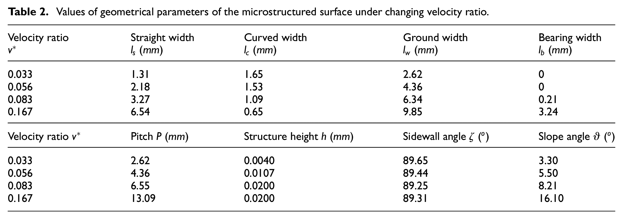
Geometrical and processing parameters designed under changing velocity ratio.
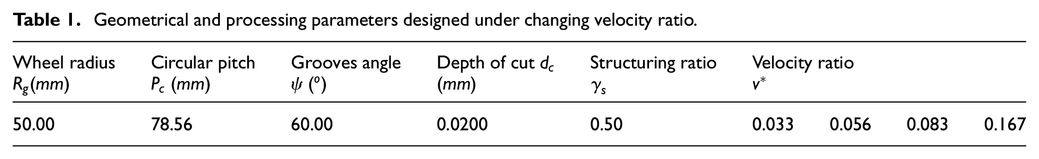
Figure 3 shows the changes in the defined parameters of the surface microstructures based on the variations of the velocity ratio
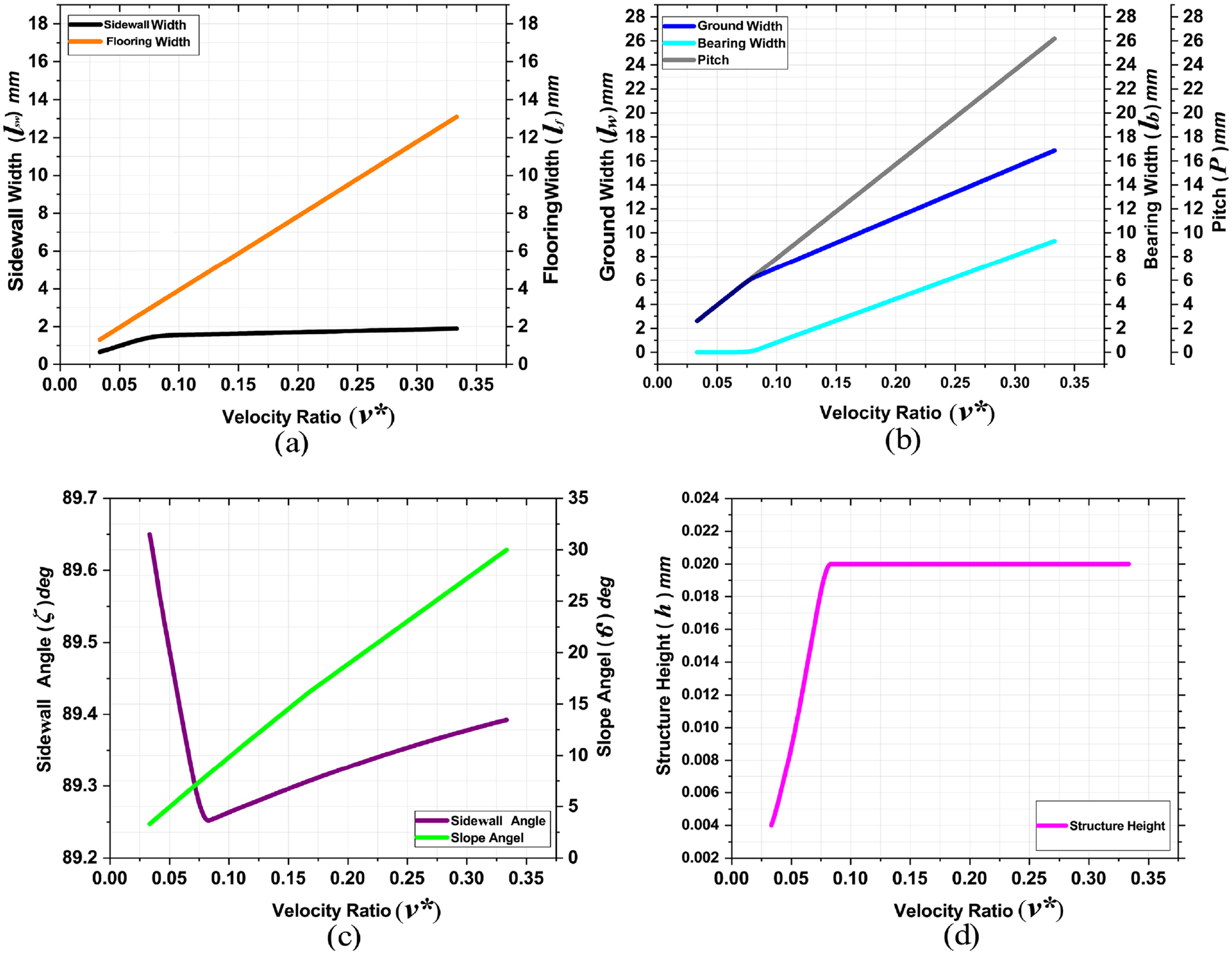
Effect of velocity ratio on geometrical parameters of the microstructured surfaces: effects on (a) sidewall and flooring widths, (b) ground & bearing widths and pitch, (c) sidewall and slope angles, and (d) height (dimensions in
Additionally, at low velocity ratios, the bearing width
Figure 3(c) and (d) show that before the inflection point of the bearing width
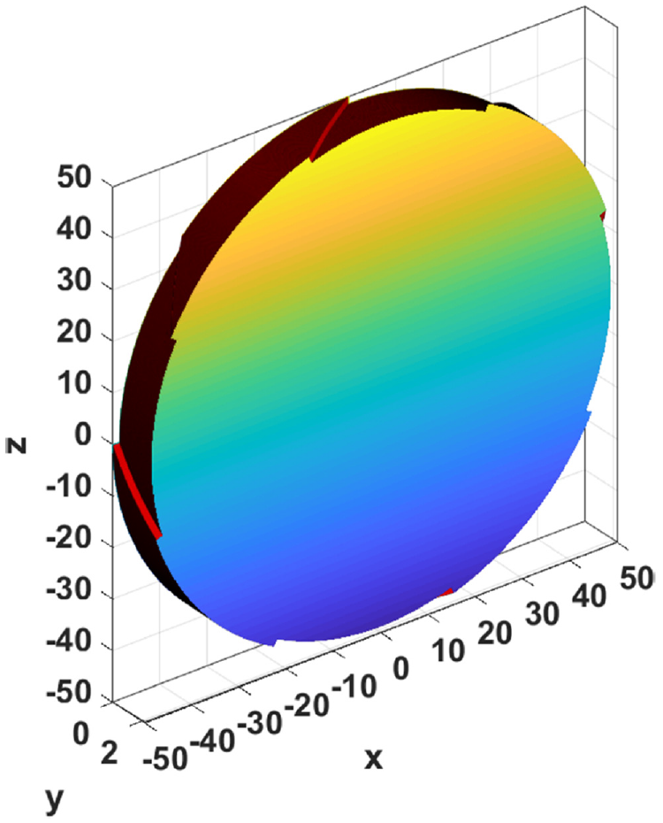
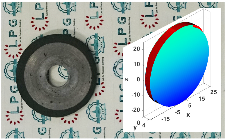
Modelled view of grinding wheel utilised to investigate effects of grinding parameters;
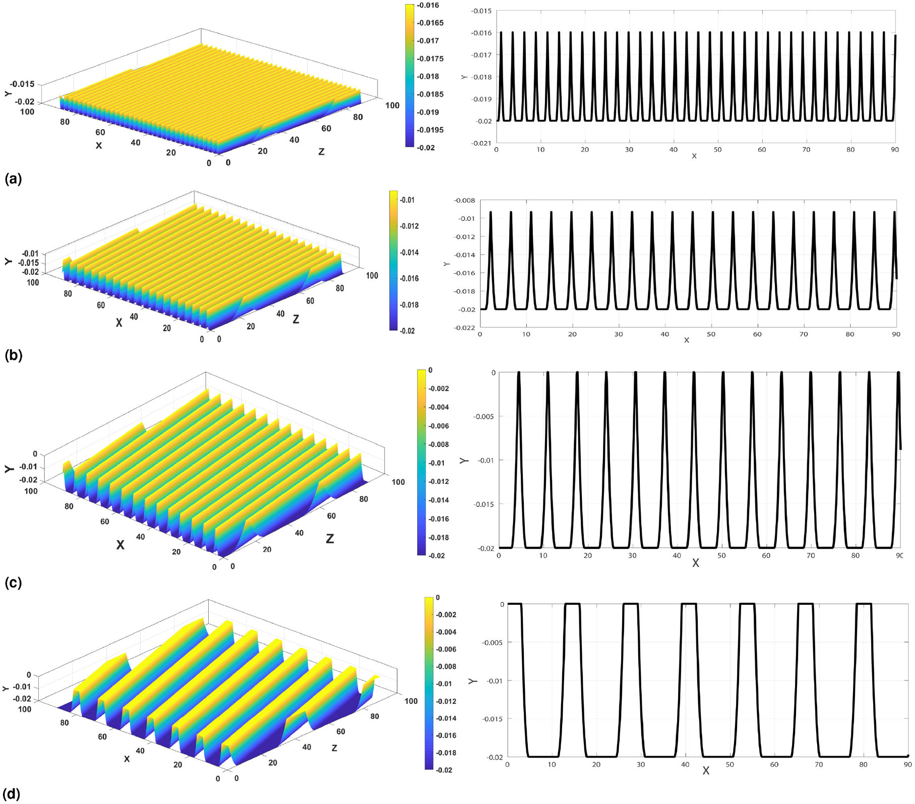
Microstructured surfaces at different velocity ratios;
Values of geometrical parameters of the microstructured surface under changing velocity ratio.
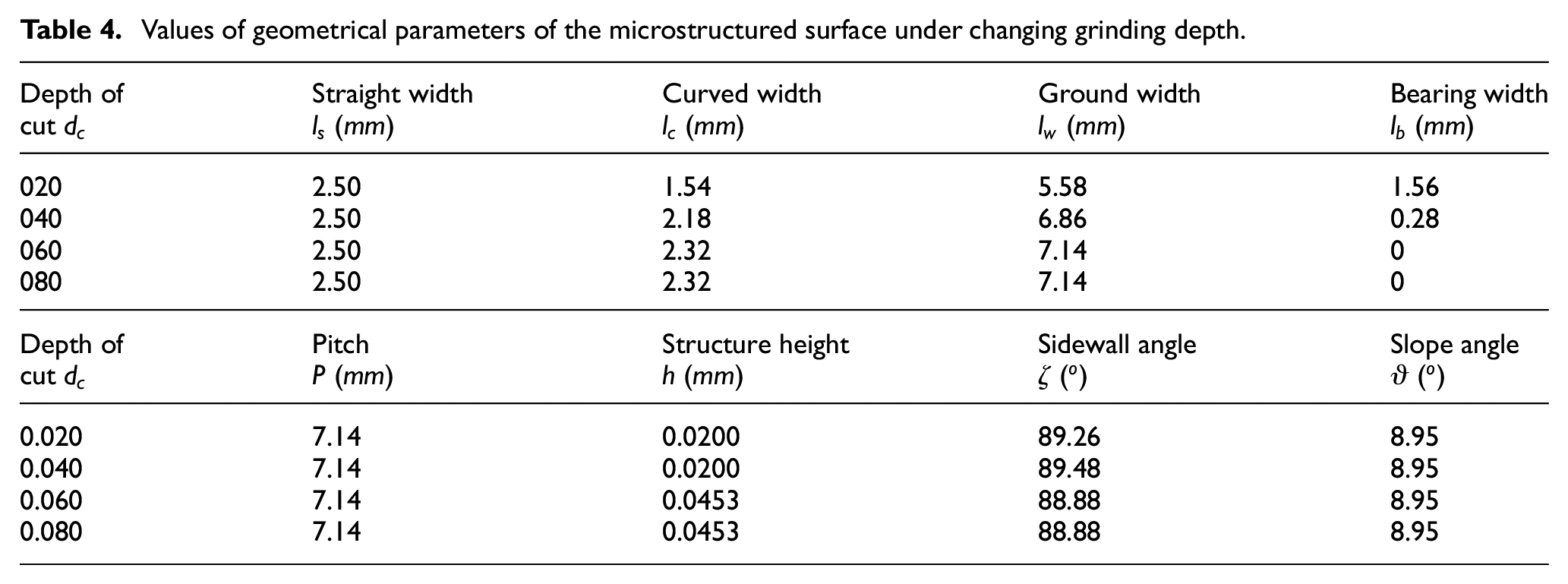
Effect of grinding depth on geometry of microstructured surface
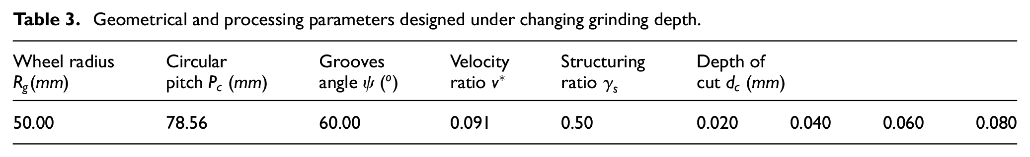
The grinding depth
Geometrical and processing parameters designed under changing grinding depth.
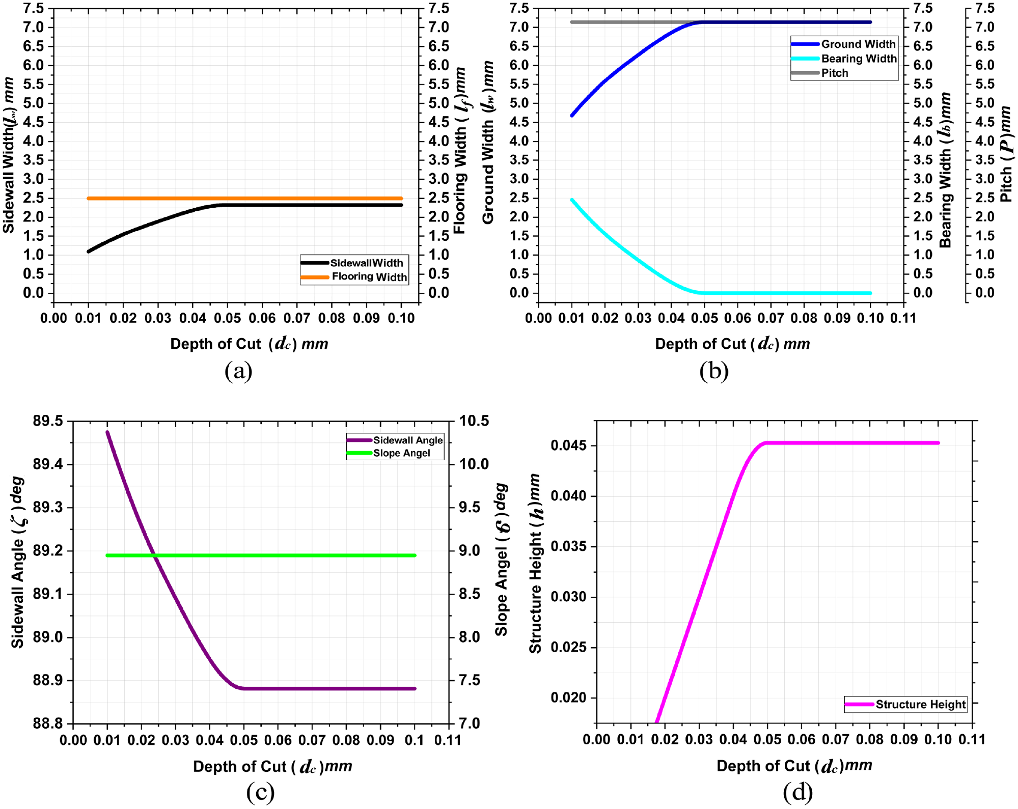
Effects of changing grinding depth on the geometrical parameters of the microstructured surfaces: effects on (a) sidewall and flooring widths, (b) ground & bearing widths and pitch, (c) sidewall and slope angles, and (d) height (dimensions in
As shown in Figure 6(a) and (b), while the surface maintains its nominal dimensions; and the grinding depth increases, the sidewall width
In addition, the ground width
Figure 6(c) and (d) shows that before the inflection point of the bearing width
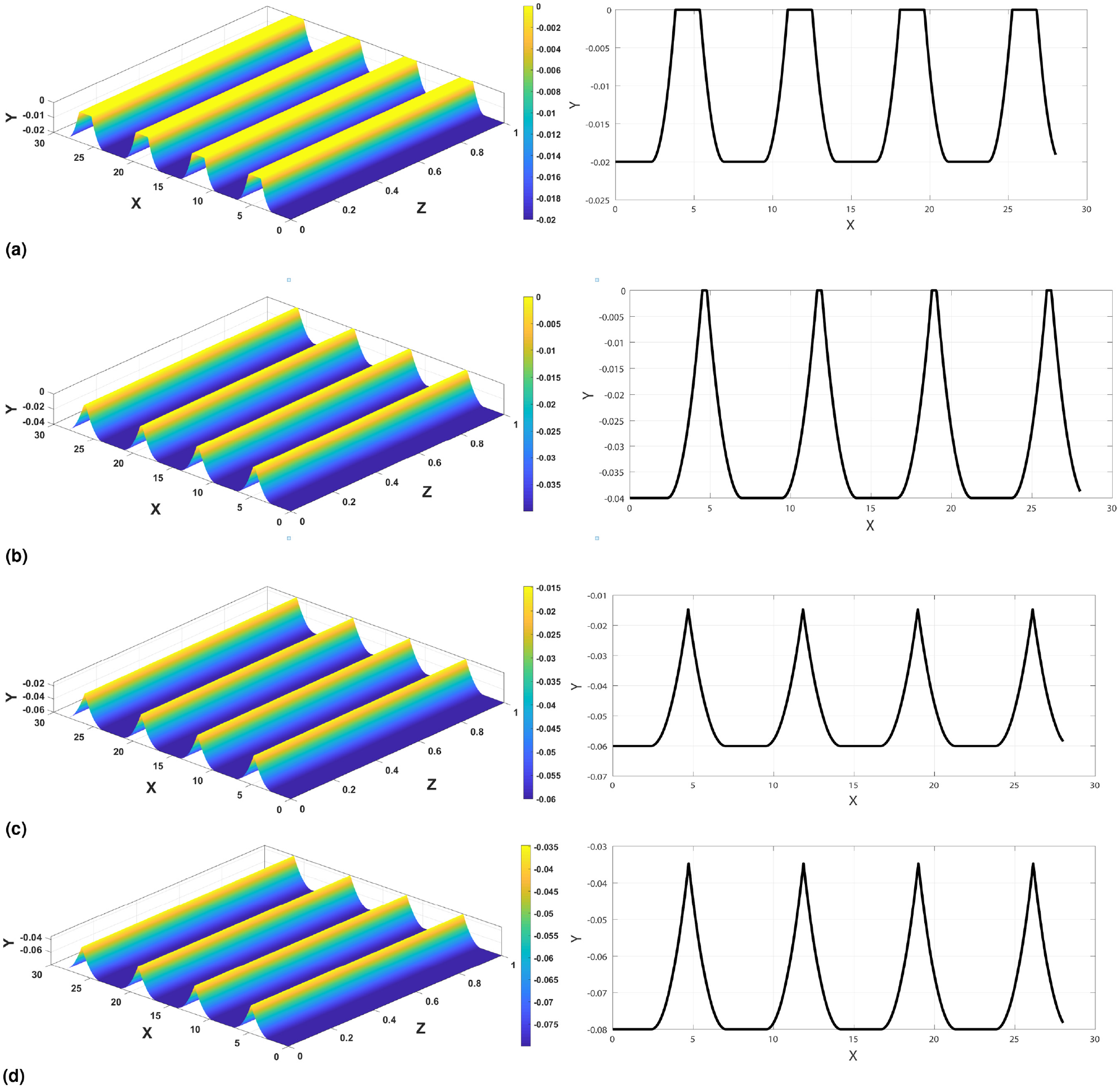
The microstructured surfaces obtained at different grinding depths;
Values of geometrical parameters of the microstructured surface under changing grinding depth.
Experiment
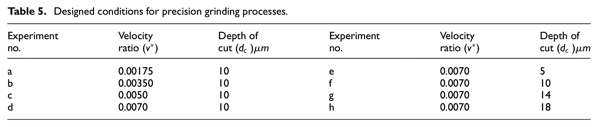
Throughout the designed precision grinding processes, surface microstructures were machined to investigate the effects of the grinding parameters experimentally and to analyse the accuracy of the presented strategy. First, using the laser structuring method explained in our earlier paper, 26 a D15 fine-grained resin bond diamond wheel was grooved and adjusted to perform the grinding operations (see Figure 8). Subsequently, the grooved wheel was installed on an electric spindle, as shown in Figure 9, and the assembly was mounted on a precision machine tool. The process was conducted by balancing the grinding wheel, minimising the runout, and performing wheel dressing using diamond block. Subsequently, samples of TC4 titanium alloy were prepared for machining the surface microstructures using the grinding assembly based on the designed grinding conditions listed in Table 5. Various conditions were considered in the designed experiments to achieve the goals of this study.
Schematic illustration and photograph of the designed laser-grooved grinding wheel.
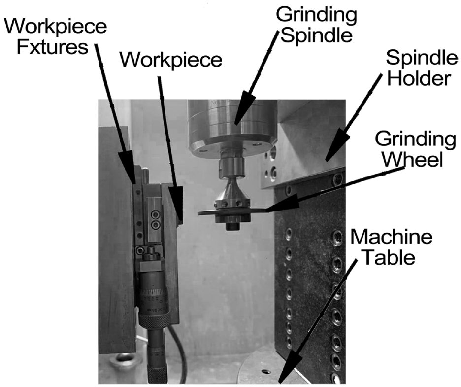
Setup for the precision grinding assembly.
Designed conditions for precision grinding processes.
Subsequently, the microstructured ground surfaces were characterised using a white-light interferometer (WLI, Nexview 3D Optical Profiler, ZygoLamda), as shown in Figure 10. The ground surfaces were analysed, and their geometrical parameters were compared with those predicted using the mathematical and kinematic simulation methods. Figure 11 summarises the results obtained using the designed parameters listed in Table 5. Figure 11(a) to (c) show the results obtained based on increasing the velocity ratio (conditions a:d in Table 5), whereas Figure 11(d) to (f) show those based on increasing the grinding depth (conditions e:h in Table 5). The contentious line represents the predicted simulated values, and each point represents the experimentally obtained value under the same conditions. The behaviours and values of the microstructure geometrical parameters predicted by the simulation method and those obtained experimentally are similar for the investigated parameters (
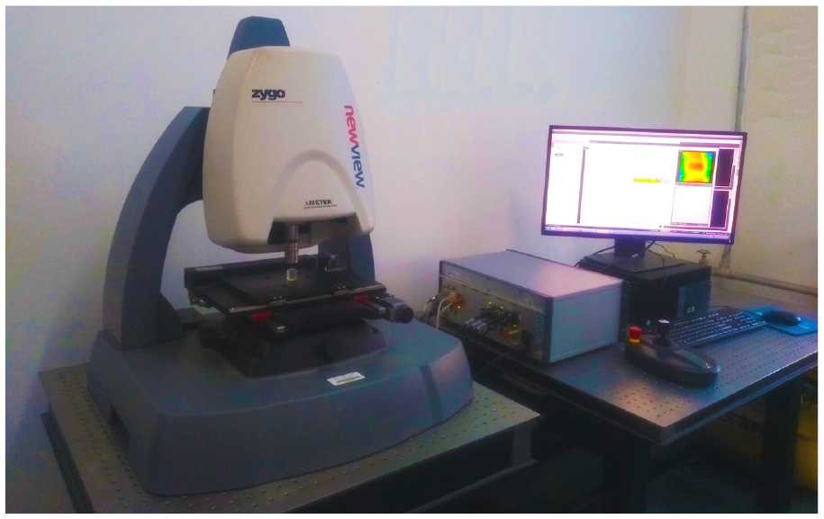
White light interferometer.
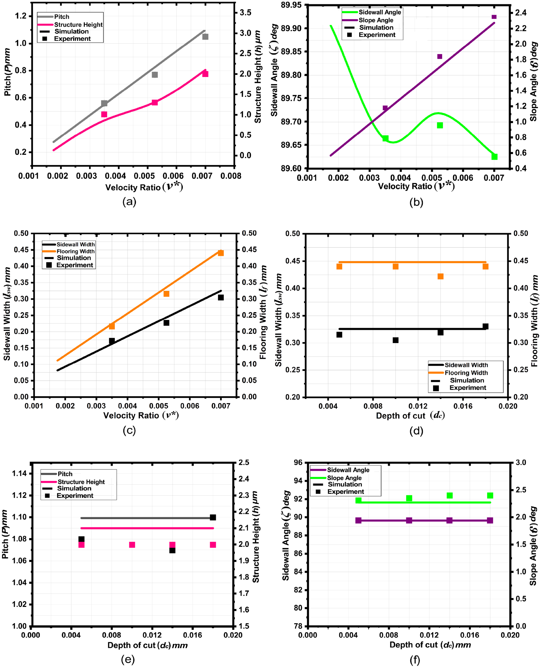
Simulation and experimental values of the microstructured surfaces for the designed grinding conditions: response of (a), (e) pitch and height, (b), (f) sidewall and slope angles, and (c), (d) sidewall and slope widths; to changes in designed parameters.
Figure 12 shows the microstructured surfaces ground at the designed velocity ratios
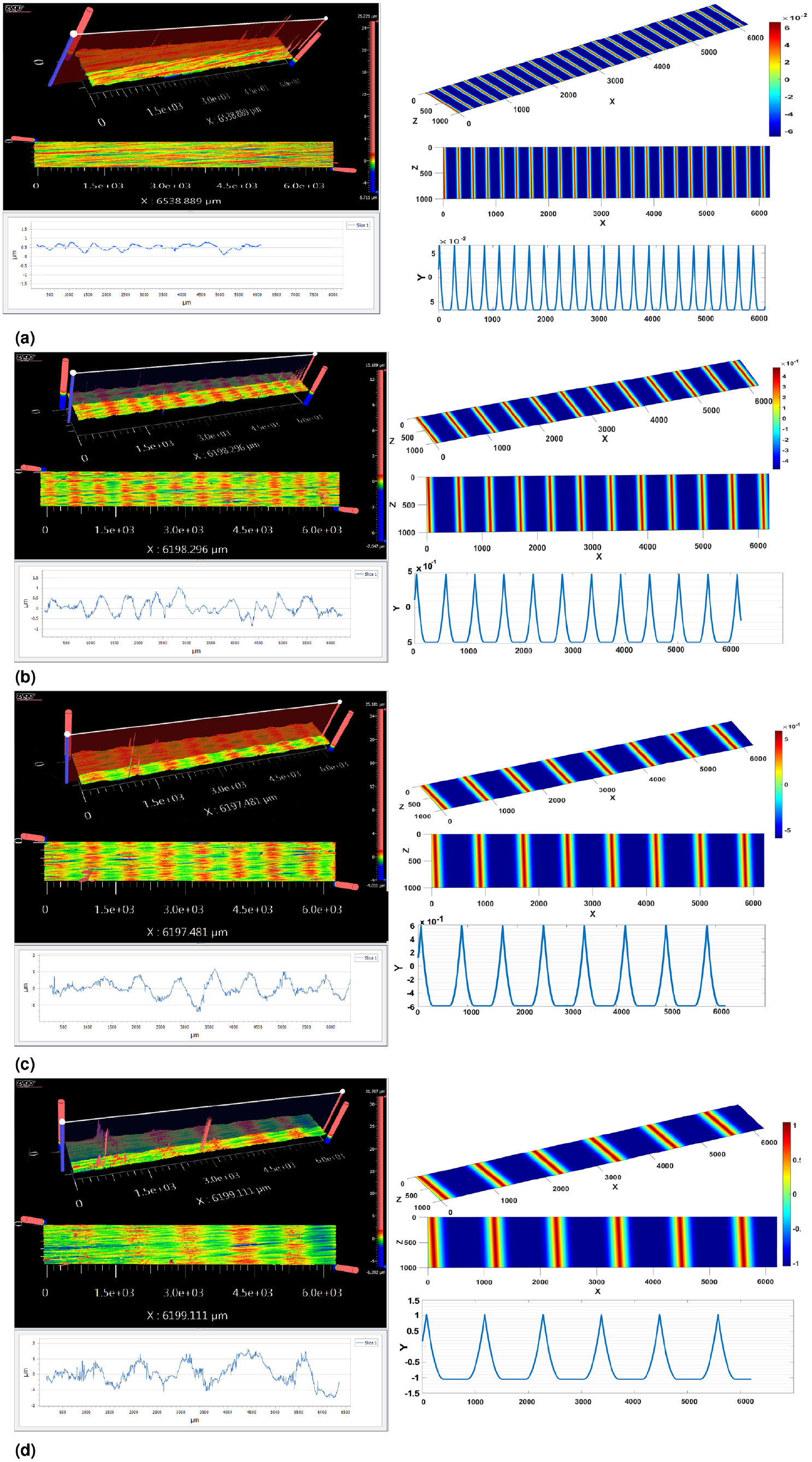
Simulation and experimental results of the microstructured surfaces under designed varying velocity ratios;
In addition, Figure 11(d) to (f) shows the results of the microstructural geometrical parameters as grinding depth
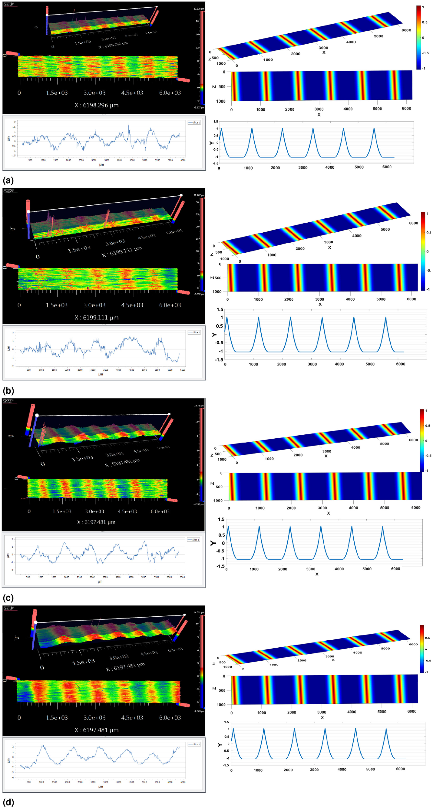
Simulation and experimental results of the microstructured surfaces under designed varying grinding depths;
Discussion
The designed operating parameters of precision grinding were analysed to investigate their effect on the final geometries of the microstructured surfaces. These parameters affect the geometries of the surface microstructures differently. In terms of the velocity ratio, the geometrical parameters of the microstructures changes significantly with respect to the velocity ratio. Increasing the velocity ratio increases the feed rate of the workpiece relative to the cutting velocity of the grinding wheel. Meanwhile, the distance swept on the workpiece surface per wheel segment increases, which consequently increases the distance separating the surface microstructures. This increase is achieved via a continuous increase in all the longitudinal pitch segments. Thus, the sidewall width, flooring width, ground width, and bearing width increase with the velocity ratio. Consequently, the number of surface microstructures per unit length decreases owing to the increase in separating distance (see Figure 14(a)).
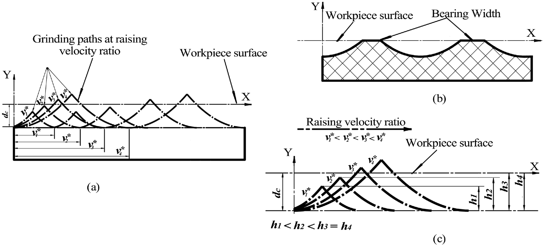
Schematic illustration of behaviour of the microstructured surface geometry for varying velocity ratio: (a) grinding cycloids at increasing velocity ratio, changes in (b) bearing width, and (c) microstructure height.
While the surface is completely removed, the increasing velocity ratio increases the microstructure heights and sidewall widths, whereas the bearing width remains unchanged. In this stage, material is added to sidewalls of the microstructures as they are being constructed, thereby increasing the heights and decreasing the sidewall angles. Once the microstructures are separated at the machined surface, the maximum height is achieved, and no additional height changes can be realised. However, the sidewall segment continues to increase with the velocity ratio; therefore, the sidewall angles change in accordance to the increase in the sidewall width (Figure 14(b) and (c))). Furthermore, the velocity ratio can control the orientation of the structures on the workpiece surface. These behaviours based on the different parameters of the microstructure geometry at varying velocity ratios match the results expects from mathematical and kinematic models explained in earlier sections, and they were determined experimentally based on the surfaces machined.
In addition, the effect of the grinding depth was investigated. Results show that the grinding depth does not affects the flooring width or separating distance (pitch). According to Malkin and Guo’s principles, 27 as the grinding depth increases, the contact length between the grinding wheel and workpiece increases. Subsequently, the height and sidewall width increase, resulting in a decrease in the sidewall angle. Furthermore, the bearing width decreases simultaneously with the sidewall width owing to the constant separating distance and flooring width values. When the workpiece surface is removed entirely, the microstructure height and sidewall width reach their maximum values, the sidewall angle reaches the minimum value, and the bearing width disappear (Figure 15).
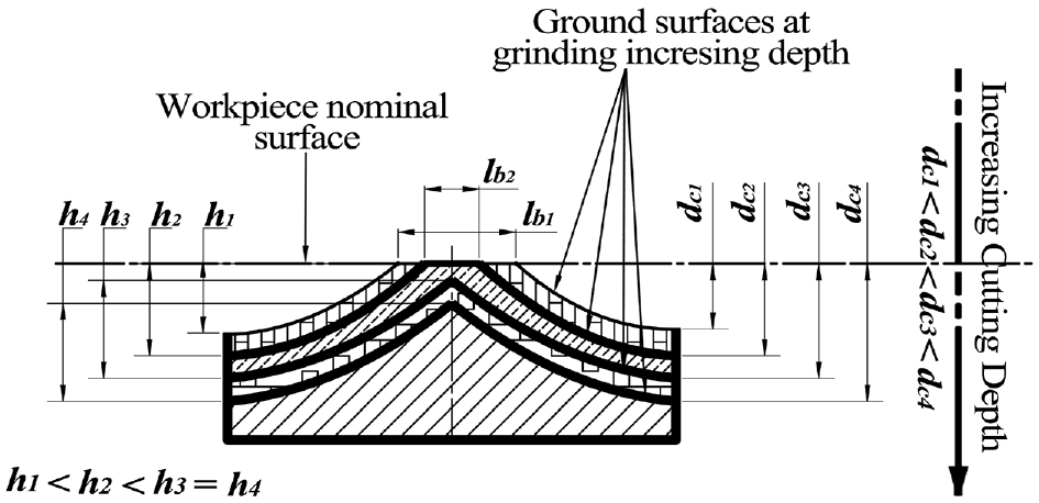
Schematic illustration of Schematic illustration of changing behaviour of the microstructured surface geometry at various grinding depths.
Subsequently, increasing the grinding depth causes the grinding wheel to penetrate deeper below the surface of the workpiece. Meanwhile, shearing occurs on the microstructures removes the outer workpiece surface at the same rate as the increasing depth owing to the constant separating distance. Consequently, the height and sidewall width preserve their maximum values, allowing the sidewall angle to maintain its minimum value owing to the constant separating distance (see Figure 15).
Conclusion
In this study, the effect of the designed operating conditions on the geometry of microstructured surfaces fabricated via precision grinding was investigated. Mathematical and simulation methods correlating the geometrical parameters of the microstructured surface to the grinding operating parameters were devised. Different operating conditions were selected. The conclusions obtained are as follows:
The appropriate velocity ratio should be selected to successfully grind the surface microstructures. An extremely low velocity ratio resulted in normal grinding operations, which failed to grind the surface microstructures.
The velocity ratio significantly affected all the designed geometrical parameters of the surfaces microstructures. The pitch, sidewall, flooring, ground, and bearing widths increased with the velocity ratio.
Before separating the surface microstructures, the sidewall angle and height of the microstructured surfaces exhibited an inverse behaviour with the increasing velocity ratio or grinding depth.
The slope angle was governed only by the designed velocity ratio in a directly proportional relationship, that is, it was not affected by the grinding depth.
The designed grinding depth affected neither the flooring width nor the pitch of the surface microstructures. By contrast, the sidewall width increased, and the bearing width decreased as the grinding depth increased.
After the surface was ground entirely, the microstructure height and sidewall width were maximised, whereas the sidewall angle was minimised. Increasing the grinding depth did not affects the designed parameters of the microstructured surface geometry.
Footnotes
Declaration of conflicting interests
The author(s) declared no potential conflicts of interest with respect to the research, authorship, and/or publication of this article.
Funding
The author(s) disclosed receipt of the following financial support for the research, authorship, and/or publication of this article: This work was supported by National Natural Science Foundation of China [Grant No.: 51875135], Enterprise Innovation and Development Joint Program of the National Natural Science Foundation of China [Grant No.: U20B2032].