
Abstract
An accurate digital model is of great significance to system operation inversion and behavior prediction. The multi-energy domain coupling mechanism of the Electro-mechanical and Hydraulic (EMH) system is complex and has strong nonlinear characteristics. At present, the research mainly focuses on the mechanical-hydraulic coupling characteristics, while the research on the large operating range and the influence of electric motor and load characteristics on the nonlinear dynamics of the EMH system are less. Based on the first principle description, the nonlinear characteristics of the system components are described in this paper. Furthermore, the nonlinear dynamic model of the EMH system described in multi-state space is established based on the Quasi-LPV system. Combined with the experimental data, the structural and non-structural uncertain parameters of system are identified. Finally, the influence of the mechanical characteristics of electric motor, load on the nonlinear dynamics of the EMH system are discussed. Experiments show that the Quasi-LPV models proposed in this paper can accurately reproduce and predict system behavior. It provides technical support for rapid design, selection, and scheme optimization of hydraulic systems in general scenarios.
Keywords
Introduction
As core equipment in the related industrial categories, the digitalization of EMH equipment is an urgent problem to meet the development of the smart factory.1–3 The digitalized EMH equipment can realize the inversion, prediction, and even diagnosis by further processing the equipment operation information received in real-time. 4 It is useful for further driving and promoting the operation of physical equipment and is of great significance to eliminate the uncertainty of a complex system.
In view of the digitalization of the EMH component and equipment, scholars have made many contributions. The EMH models presented in the literature5–7 consider the linear relationship between losses and system variables. They treat the system or component as a linear system within a specific operating range. However, literature 8 pointed out the flow and the torque loss of hydraulic components are correlated with pressure and speed, and show a nonlinear relationship. Especially when the EMH system operating within a wide operation range or an extreme operation condition, the linear model would deviate from the actual operating results.8–10
To study the nonlinear property of the EMH system, the characteristics of the components should be understood first. Mandal et al. 11 uses polynomial to fit the axial piston pump leakage resistances, where the load torque and speed are regarded as dependent variables. Jeong 12 and Gu et al. 10 describes the causes and characteristics of the nonlinear loss of piston hydraulic equipment based on the first description principle. Geng et al. 13 clarifies the nonlinear compression loss resulted from the air content of the oil in detail and proposes an improved flow loss model of the piston pump. Xu et al. 14 propose a volumetric loss model considering lubrication gap.
In addition to the influence of components characteristics on system performance, the characteristics of hydraulic oil cannot be ignored. 15 A small amount of entrapped air can drastically reduce the bulk modulus of oil. 16 The study of Akkaya 17 shows that the nonlinear bulk modulus has obvious influence on the dynamic response of the EMH system. Geng et al. 18 propose an effective model to measure the air content of oil and verified the complex nonlinear dynamic relationship between the oil bulk modulus and the operation conditions.
The nonlinearities in such a system are not a simple superposition of the system component characteristics. It is relatively easy to describe the working characteristics of each component separately. However, when the components are assembled, the system behavior becomes complication. Some scholars have proposed new models to simulate the nonlinear characteristics of the EMH system. Considering the linear relationship between the bulk modulus of oil and pressure, Wu et al. 19 identify the parameters of each transfer function of the hydraulic transmission system through sine excitation. Kumar et al. 20 describe the transmission characteristic of a closed-circuit hydraulic summation drive system based on the bondgraph simulation technique. Implementing a flawless model for nonlinear EMH systems with a wide range of operating points requires sufficient knowledge about the system dynamics. Derived from the piecewise affine system, Vaezi and Izadian 9 propose the polytopic LPV models to study the nonlinear characteristics of the electromagnetic proportional valve in the wind power transmission system within the large working voltage range.
Looking back on the above nonlinear dynamic models, scholars have achieved goals to some extent. However, based on the experimental fitting and empirical parameters, the individual terms of the model coupling equations are assembled to fit the data as best as possible, that have little physical meaning. And the power source was oversimplified as a constant speed, which ignored the role of the dynamic characteristics of the electric motor in the EMH system.
This paper describes the causes and characteristics of the nonlinear loss of hydraulic equipment by mathematic functions based on the first description principle. Then, considering the nonlinear bulk modulus of fluid, mechanical characteristics of the Emotor (electric motor), and the nonlinear loss of hydraulic components, the dynamic nonlinear state equations for the dynamic of variable speed EMH system are established. Furthermore, the nonlinear state equations are converted into Quasi-LPV (Linear, Parameter Vary) model. The reliability and accuracy of the Quasi-LPV model are verified by experiments. Finally, the influence of power source and load on the dynamic characteristics of the EMH system is discussed in combination with the proposed model and experiment.
The variable speed EMH MISO system description
The schematic of the variable speed closed-circuit EMH system considered in this paper is shown in Figure 1. This EMH system is mainly composed of three parts: the powertrain, the closed-circuit hydraulic transmission system, and the loading system. The inverter fed motor 2 is driven by inverter 1. The power is delivered from the powertrain to hydraulic pump 5. Then, pump 5 converts mechanical power into hydraulic energy which drives the hydraulic motor 11 to drag the load. The precise control of the load torque can be achieved by adjusting the voltage-controlled proportional valve 16. Table 1 is the main technical parameters of the key components and sensors
The main technical parameters of the key components and sensors.
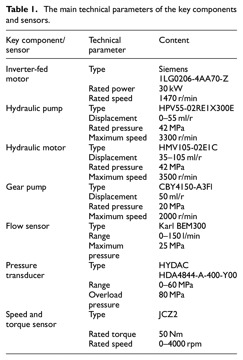
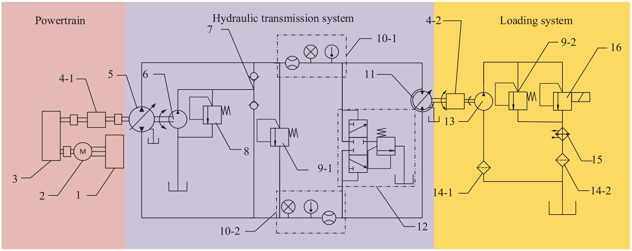
The brief schematic of the test bench. 1. Inverter, 2. Inverter fed motor, 3. Gear box, 4-1, 4-2. Speed and torque sensor, 5. Pump, 6. Charge pump, 7. Check valve, 8. Relief valve, 9-1, 9-2. Safety relief valve, 10-1, 10-2. Sensor group, 11. Hydraulic motor, 12. Loop flushing valve, 13. Gear pump, 14-1, 14-2. Filter, 15. Radiator, 16. Relief valve.
As depicted in Figure 2, the EMH system consists of three input ports (
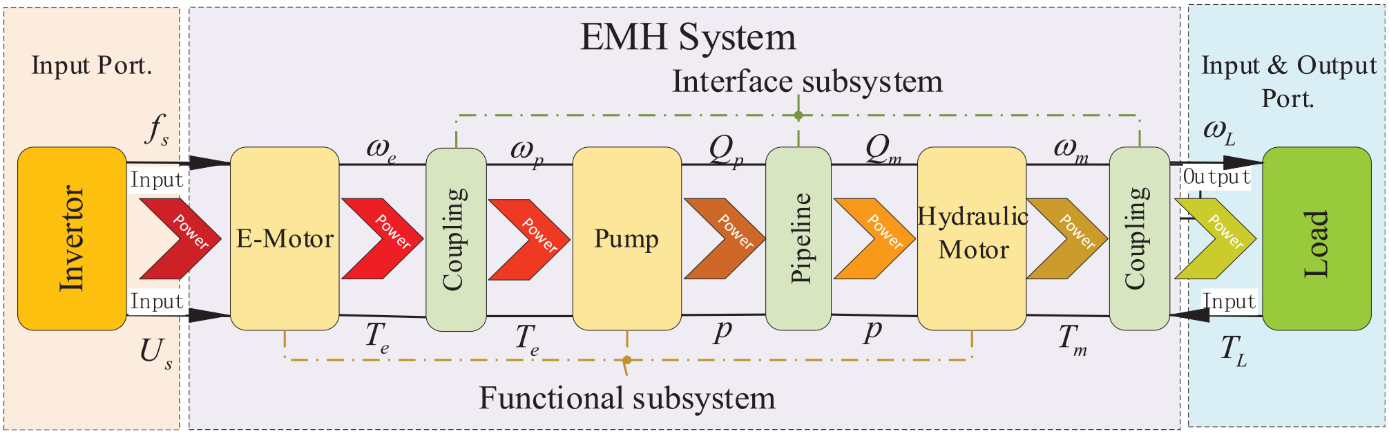
The MISO system structure of the EMH system.
The mathematic description of functional subsystem
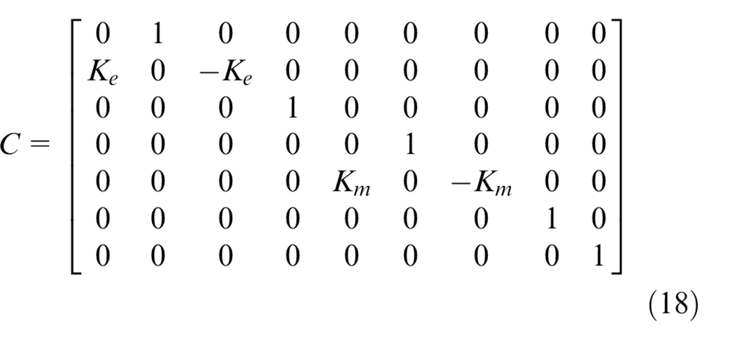
Powertrain
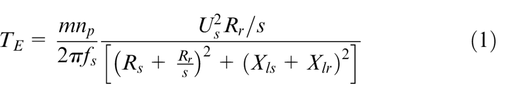
The Emotor stiffness characteristic would map to the load through the mechanical-hydraulic coupling. 21 The E-motor torque characteristic equation (1) is derived by the asynchronous motor operating state equations.
Where, s is the slip ratio,
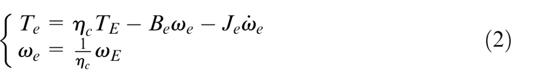
Where,
Axial piston pump
There are three types of key kinematic pairs within swash-plate axial piston pump 12 : slipper swash plate pair (SSP), piston cylinder pair (PCP), and cylinder valve plate pair (CVP). The steady-state characteristics of the axial piston pump are described respectively as follows.
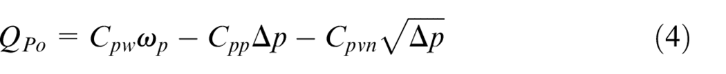
The flow characteristics
After the low-pressure oil is sucked into the piston cavity, the flow is further compressed by reciprocating pistons and exported to the next subsystem for further transmission. According to the loss characteristics 13 provide in Appendix 1, the flow continuity equation of the pump is shown in equation (3).

Where,
The delivery flow of the pump is calculated by substitute equations (A1)–(A5) in Appendix 1 into equations (3).
Where,
The torque characteristic
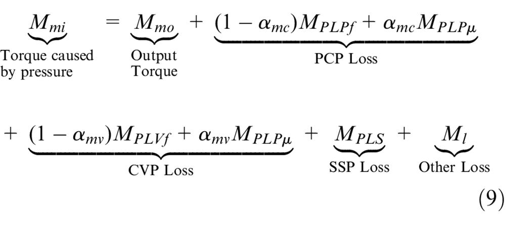
According to the characteristics of the torque loss, it can be divided into Coulomb friction loss and viscosity loss. The valve plate on the side of high pressure cavity is subjected to the separation of the high pressure oil. The viscosity loss is the main factor. However, on low pressure cavity side, there is no leakage caused by pressure difference, the lubrication of CVP is supported by the adsorbed oil film. The Coulomb friction loss is the main factor. Similarly, the Coulomb friction loss caused by local contact between cylinder and piston, and the viscous loss of the oil in the kinematic clearance of PCP coexist. Therefore, the mixed lubrication occurred in CVP and PCP during the operation.
With respect to the mixed lubrication state of CVP and PCP, the mixed friction weight of CVP
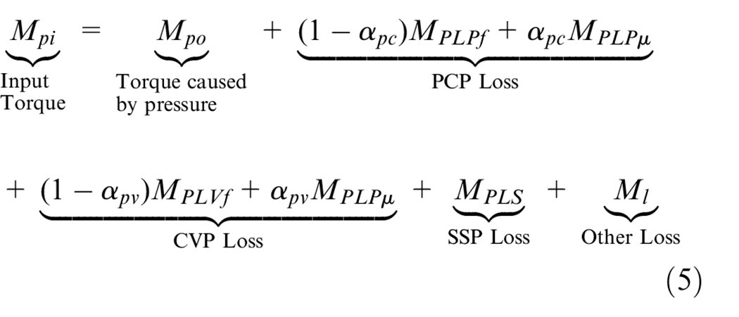
The input torque of pump is calculated by equations (5), and (A6)–(A11) in Appendix 1.

Where,
Hydraulic motor
The piston motor dragging the load by converting the hydraulic energy to mechanical energy. Its structure is like the piston pump. Therefore, by modifying the piston pump, the modeling of the piston motor can be achieved.
The flow characteristic
Without considering the pressure loss of hydraulic oil along the pipeline, the pressure of the motor is always consistent with that of the pump. During the steady-state operation conditions, the oil does not release the stored compression energy while pushing the piston, nor is it further compressed. The compression energy of oil does not change. According to the loss characteristics of the kinematic pairs provide in Appendix 1, the flow continuity equation of the axial piston motor is shown in equation (7).

Where,
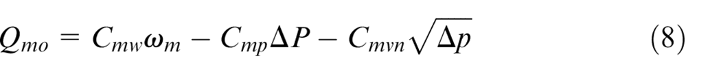
Where,
The torque characteristic
Similarly, considering the mixed lubrication characteristics of kinematic pairs, the torque balance equation (5) can be derived.
Where,

Where,
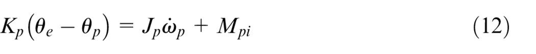
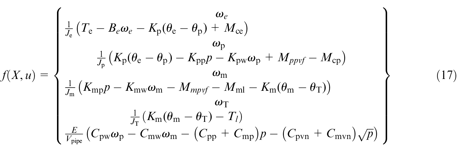
Dynamic modeling of EMH system
It is relatively easy to describe the working characteristics of each component separately. However, when the components are assembled into the EMH system, the system behavior becomes complicated. According to the equilibrium relationship of torque and flow of subsystems, the system dynamic equilibrium equations can be obtained.
E-motor torque equation:
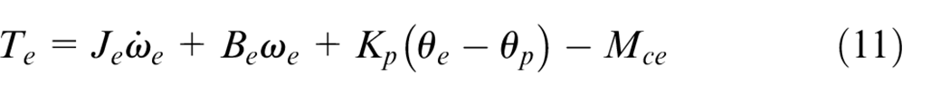
Pump torque equation:
Hydraulic motor torque equation:

Load torque equation:

Flow equation of pipeline:
Denote the system state vector
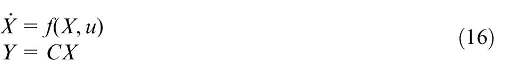
Where,
The state-space description of the LPV system is known functions of time-varying parameters. The time variation of each of the parameters is not known in advance but is assumed to be measurable in real-time.9,22 By continuously measuring the time-varying parameters in the state-space, the system matrix is recorrected in real-time, so that the simulation results are within the acceptable error. That means each linear model will have an effective range, in which the system generates minimum deviation from the original function.
A quasi-LPV system is defined as a linear time-varying plant whose state-space matrices are fixed functions of some varying parameters that depend on the state variables. 23 The quasi-LPV system is similarly closed-loop control mode which refreshes the nonlinear parameters according to the system state variables.
Obviously, due to the existence of nonlinear components, equation (16) shows strong nonlinear characteristics. Those nonlinear factors are uniquely determined by state variables. By deducing the equation (17), all nonlinear factors are controlled by the system pressure and pump rotation speed. Therefore, the system equation (17) can be expressed as Quasi-LPV systems after suitable conversion.23,24
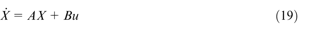
Where,
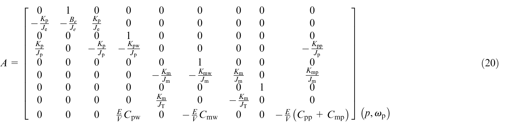
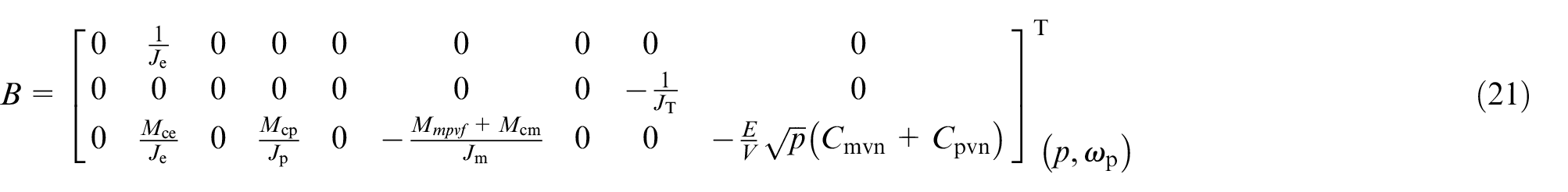
The system matrix A and control matrix B are determined by the scheduling variables
The workflow of the Quasi-LPV system is depicted in Figure 3. The scheduling variables
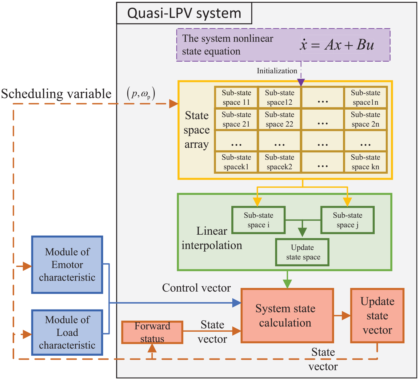
The workflow of the Quasi-LPV system.
System parameter identification
Most parameters in section 3 and section 4 can be obtained through user manuals or mapping. Some necessary parameters have been shown in Table 1 and the Appendix Table 1. However, some non-structural uncertain and structural uncertainties (e.g. the clearances of kinematic pairs) are comprehensively determined by operation condition and cumulative using time. Those uncertain parameters determined by the performance degradation of components and operating environment need to be identified by experiments.
The identification of structural uncertain parameters
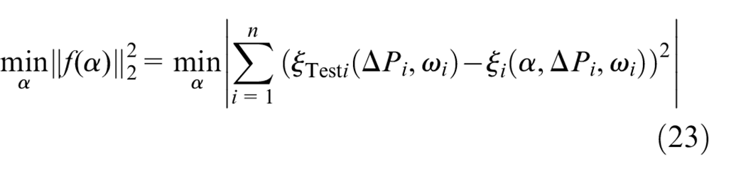
Volumetric efficiency of hydraulic pump and motor are sensitive to the degradation of kinematic clearances (KCs). To realize the identification of KCs, the least square method is used to obtain the optimal fitting of the simulation and experimental results of the component volumetric efficiency. The objective function is shown as equation (22). 13
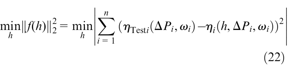
With respect to the piston pump, under the specific operation condition
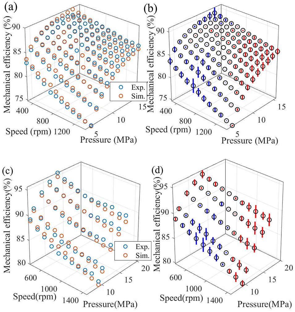
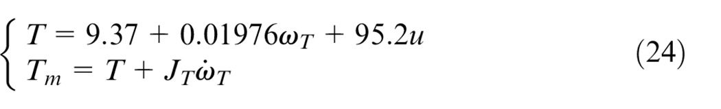
Table 2 is the identified results of structural uncertain parameters. Figure 4 is the results of the experiment and simulation. Obviously, the volumetric efficiency shows strong nonlinear characteristics with the varying of operating conditions.
The identified results of structure uncertain parameter.
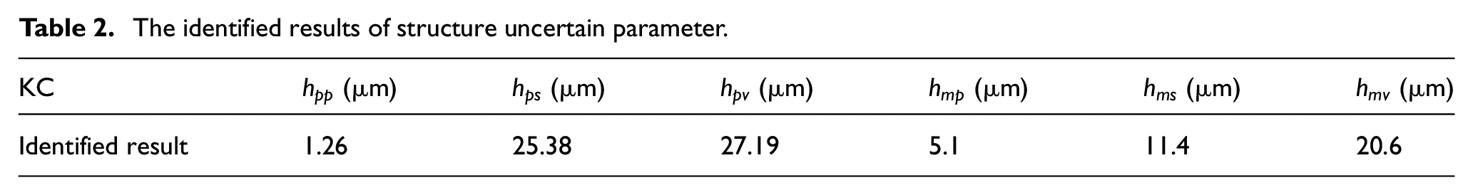
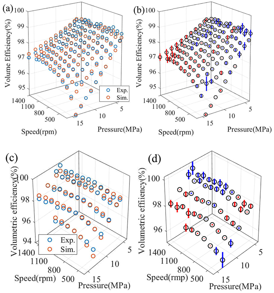
The volumetric efficiency identification results of pump and motor: (a) the experimental results and the simulation results of pump, (b) identification error of pump, (c) the experimental results and the simulation results of motor, and (d) identification error of motor.
The identification of non-structural uncertain parameters
The nonlinear bulk modulus of oil
Air content has a great influence on the bulk modulus of oil. Literature 16 has pointed out that air content in oil decrease with compression and dissolution. Compression can be completed instantaneously. However, the dissolution takes time. When the valve plate of the pump connects the low pressure piston cavity and the high pressure cavity, the high pressure oil is poured into the piston cavity quickly, and the oil is compressed instantly. Since the compression of the liquid inside the piston pump is instantaneous, the dissolution of bubble can be ignored during the compression process. However, the flowing oil in the pipeline is like pressure holding. The dissolution of bubbles inside liquid should be considered. The air content of the liquid has been estimated in literature. 18 It also provides a dynamic model for the bulk modulus of oil in the pipeline. It would be cited in this article.
The weight of mixed friction and the friction coefficient
The mechanical efficiency of the piston pump and the motor is sensitive to the degradation of the mixed friction state of the kinematic pair. The varying of the KCs caused by wear and tear would cause the variation of the mixed friction weight, and even lead to the deterioration of the Coulomb friction coefficient. Therefore, to describe the torque characteristic of the hydraulic component, the identification of the mixed friction weight and the friction coefficient is needed. The objective function of the identification is shown as equation (23).
With respect to the piston pump,
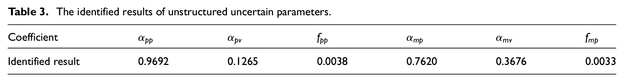
Table 3 is the identified results of unstructured uncertain parameters. Figure 5 is the results of the experiment and simulation. It is obvious the mechanical efficiency shows strong nonlinear characteristics with the varying of operating conditions. The identification results also illustrated that the friction state of PCP and CVP are dominated by fluid lubrication, and there is also oil film lubrication.
The identified results of unstructured uncertain parameters.
The mechanical efficiency identification results of pump and motor: (a) the experimental results and the simulation results of pump, (b) identification error of pump, (c) the experimental results and the simulation results of motor, and (d) identification error of motor.
Load characteristics
The gear pump is used to simulate the dragged load in the test bench. By controlling the proportional valve, the operating pressure of the gear pump is govern to simulate the drag load of the EMH system. The linear operating range of the electro-hydraulic proportional valve is selected for the experiment. The relationship between control voltage, load speed, and torque of the proportional valve is fitted by polynomial. Equation (24) is the dynamic equation of load.
Simulation and experimental verification
According to the system parameter identification results in section 5 and the Quasi-LPV model in section 4, the simulation of the experiment can be realized. All the calculations and simulations in this paper are completed in MATLAB version R2018a and the corresponding Simulink.
Figure 6 shows the physical photo of the test bench. The inverter is set to the mode of V/f with linear characteristic, in which the input voltage
Experimental description and purposes.
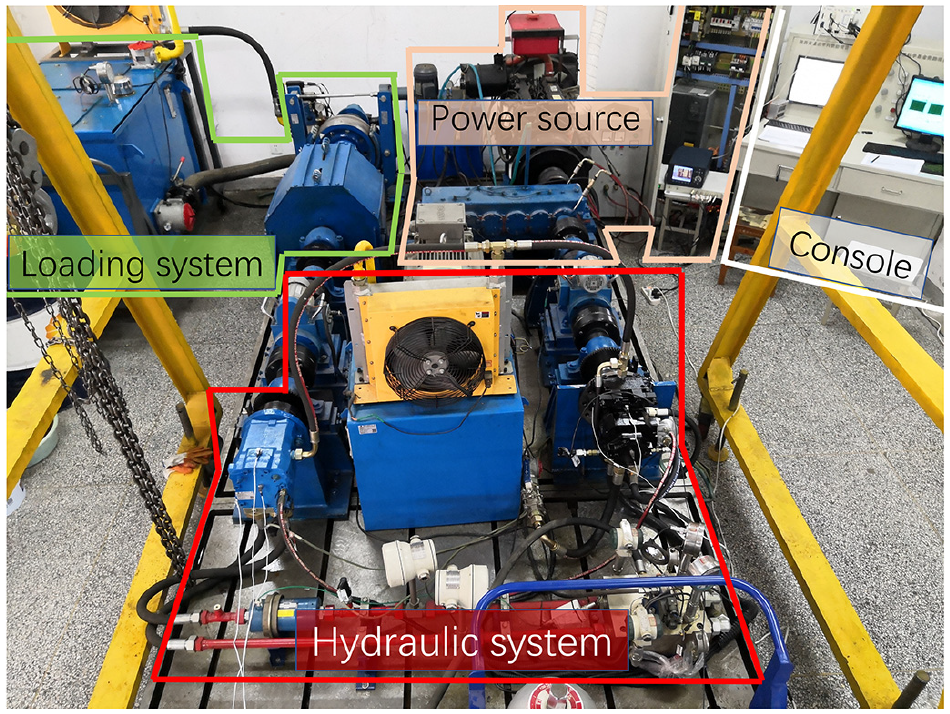
The photo of test bench.
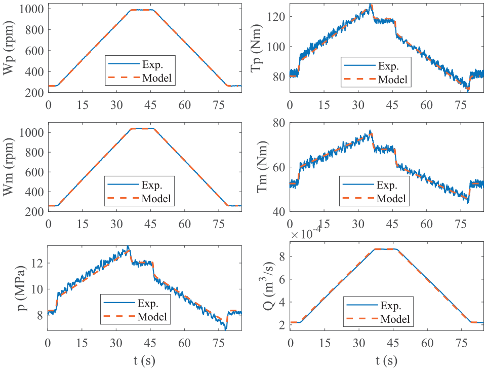
Results of the Case 1.
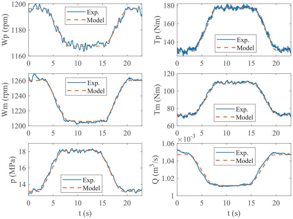
Results of the Case 2.
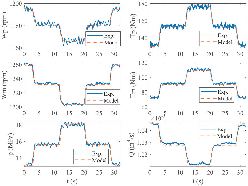
Results of the Case 3.
In case 1, when the system is accelerated from 280 to 1000 rpm, the torque or pressure of each subsystem shows step characteristics at the beginning and end, due to the influence of the system inertia. When the speed of the system is accelerating, the powertrain needs to output additional torque to boost system kinetic energy. Conversely, the output torque of the powertrain is less. The model accurately reproduces the state variables under the operation conditions of large-scale speed.
In case 2, with the increase of the load, the speed or flow of each subsystem decreases slightly due to the E-motor stiffness and hydraulic system leakage. Conversely, with the decrease of the load, the system speed recovered.
Case 3 applied a step voltage to the proportional valve to verify the dynamic response of the EMH system. Step load causes the varying of rotation speed and torque. Due to the larger inertia and damping of the system, the overshoot phenomenon does not occur under the step operation conditions.
It is observed that the Quasi-LPV system accurately describes the nonlinear dynamic characteristics of the system. The experimental results verified the effectiveness of the model.
Expanding research
The characteristics of load and power source directly affect the performance of the EMH system. Based on the proposed model, the character of the system under different load inertias and motor stiffness are studied by simulation. Two motors with different stiffness characteristics are shown in Figure 10. The inverter is set to the mode of V/f with linear relationship, and the input frequency is set to 27.74 Hz. The load inertia of the system is set to
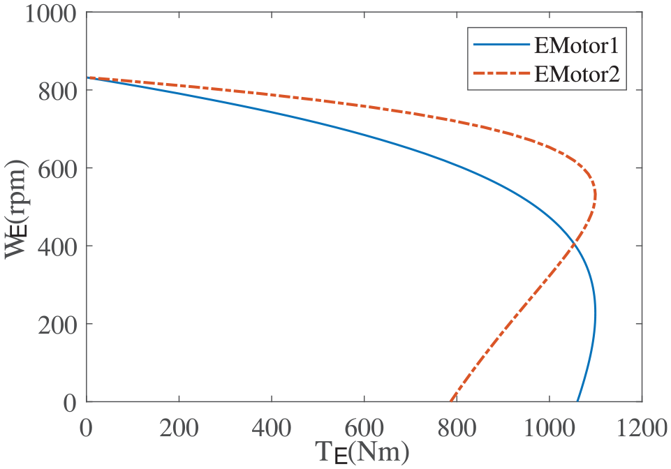
Emotor with different stiffness.
Figure 11 is the dynamic response of the EMH system with different Emotor and load inertia. The horizontal segments of the curves can represent the steady state characteristics of the system approximately, and the curve segments represent the dynamic response of the system. It can be observed that the varying of the load inertia does not affect the steady state performance of the system (the blue and red curves’ horizontal sections are overlapping). To the dynamic characteristics, the greater the load inertia (blue curve), the slower the system response and the longer the adjustment time.
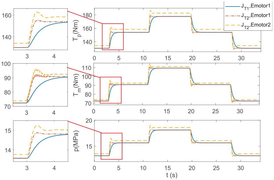
The dynamic response of different Emotor and load inertia.
Generally, to increase the stability of the output speed, improving the mechanical characteristics of the motor is the simplest way. The effects of different motor mechanical properties on the system performance are illustrated by the red and yellow curves in Figure 11. Obviously, the increase of motor stiffness (the yellow curve) not only affects the static characteristics of the system, but also affects the dynamic characteristics of the system.
In engineering, speedless feedback vector control (SFVC) or direct torque control of the motor is often introduced in the inverter to improve the stability of the motor output speed. By comparing the response of SFVC control mode and V/F mode with linear characteristics to step load (Case 3 in Table 4), this paper discussed the influence of power source rotational speed stiffness on the dynamic characteristics of the system. The experimental results show in Figure 12. Obviously, the SFVC (red curve) causes system oscillation, and the response speed of the system is not significantly improved.
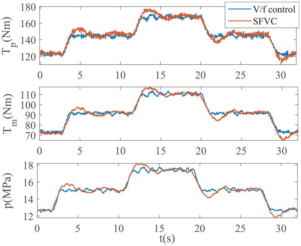
System dynamic characteristics under different control modes.
The electromagnetic field between stator and rotor can be regarded as a nonlinear electromagnetic spring. Obviously, it is not that the higher stiffness of the electromagnetic spring, the better the stability and rapidity of the system response. In other words, it is not accurate to evaluate the dynamic characteristics of the system simply by using the static characteristics of the system.
Therefore, in the scenario where the dynamic of the system is required, simply changing the speed stiffness of the power source to improve the static characteristics of the system may cause the deterioration of the dynamic characteristics of the system. To get a better characteristic of the EMH system, it is necessary to combine the digital model at the beginning of the design to fully couple the stiffness characteristics of each subsystem of the EMH system.
Conclusion
The mathematic description of the nonlinear characteristics of the EMH system is challenging, especially under operation conditions of large-scale speed governing and load wide-ranging varying. The main contributions and results of this paper can be concluded as follows:
(1) The nonlinear characteristics of the key hydraulic components are described based on the first principle, and the identification method of structural and non-structural uncertain parameters of key hydraulic components are proposed. The identification results explained the quantitative relationship of the two friction states in PCP and CVP. It is illustrated the friction state of PCP and CVP are dominated by fluid lubrication, and there is also oil film lubrication.
(2) Based on Quasi-LPV system, a nonlinear dynamic model of EMH system described in multi-state space is established. The proposed model can accurately predict the nonlinear operation of the EMH system with large-scale speed and load regulation. It provides technical support for rapid design, selection, and scheme optimization of hydraulic system in general scenarios.
(3) Interface subsystem and function subsystem should be reasonably matched at the beginning of the system design, especially the selection of the Emotor stiffness and control mode, which requires considering both dynamic and static performance of the system. Simply pursuing the speed stability of steady-state conditions would cause the loss of system dynamic characteristics.
Footnotes
Appendix 1
Declaration of conflicting interests
The author(s) declared no potential conflicts of interest with respect to the research, authorship, and/or publication of this article.
Funding
The author(s) disclosed receipt of the following financial support for the research, authorship, and/or publication of this article: This work was supported by the National Natural Science Foundation of China [No. 51675399].