
Abstract
Current processing methods of face gear are mainly limited to gear shaping, gear hobbing, and other processes. In order to achieve high-precision and high-efficiency machining of face gear, this paper proposed the cutting technology and tool design of face gear skiving. Solving the tooth surface of the skiving cutter according to the meshing principle, and fitted by NURBS surface. Intersecting the rake and conjugate face to obtain cutting edge data, and import it into the CAD software to build the skiving cutter model, the tooth surface enveloped by the cutting edge of the skiving tool is solved according to the envelope principle. This paper proposed the machining principle and tool design method of face gear skiving and analyzed the influence of tool tooth profile error and installation error on the face gear tooth surface deviation, which provides a reference for improving the machining accuracy and efficiency of face gears and further improving the gear skiving process.
Introduction
Because of the advantages of high bearing capacity, and low sensitivity to installation error, face gear is used in various fields.1–7 Due to the complex structure, the processing methods of face gear are mainly limited to gear shaping, gear hobbing, etc. Many scholars have carried out a lot of research on face gear, especially in processing.8–10 Litvin’s group carried out systematic and comprehensive research on face gear drive.1,2 Zschippang analyzed the tooth surface generation and contact characteristics of face gear. 3 Mo et al.4–7 systematically studied the gear design theory and the load distribution uniformity mechanism of the gear transmission system. Based on the principle of meshing, Tang and Yang 8 proposed a planning method for machining spur gears with a four-axis CNC planer and used simulation software to verify the feasibility of the method. Based on the analysis of the features of the tooth surface, Peng 9 proposed a method for determining the tooth surface of a face gear with a straight-edged tool. Wang et al. 10 presents a generating milling method for the spur face gear using a five-axis computer numerical control milling machine and proposes a milling principle of the spur face gear using a milling cutter, and carried out the face gear milling experiment on the self-developed milling machine. Traditional face gear machining methods are less efficient and accurate. Therefore, seeking a high-precision and efficient machining method and tool has become an important direction of face gear research.
Gear skiving is a new processing technology that directly cuts the tooth profile from the blank, which can realize continuous and efficient indexing processing.11–25 Stadtfeld 11 pointed out that the production efficiency of gear skiving process is higher than that of gear hobbing and gear shaping. There are few research results on gear turning machining. Based on the curved surface design theory, Li et al. 12 proposed a structure design suitable for cutting involute cylindrical gears, it provides a reference for the design of gear skiving cutter. Guo et al.13,14 studied the calculation method of the tooth profile error of skiving, and analyzed the influence of the scraping tool sharpening and rake angle on the tooth profile error of the gear. Guo et al.15,16 proposed a new type of more efficient conical skiving tool, and analyzed the machining error of CNC gear skiving. Zhenyu et al. 17 analyzed the influence of shaft angle error on the machining accuracy of gear skiving. Tsai 18 proposed a comprehensive yet straightforward methodology for the design of resharpening power skiving tools based on conjugate surface theory. Uriu et al. 19 discussed the influence of shaft intersection angle on tool parameters during internal gear cutting, and verified the common values of shaft angle through cutting simulation and experiment. Jinzhan et al. 24 proposed to deduce the skiving tool model according to the modified rack tool and analyzed the error. Based on the envelope principle, Jia et al. 25 analyzed the machining model of gear scraping tool.
At present, the skiving processing is mostly used in the machining of cylindrical gear, some achievements have been made in the design of gear skiving tool and CNC machine, but this technology has not been used in the processing of face gear. In order to improve the machining accuracy and efficiency of face gear, this paper proposed the machining principle and tool design method of face gear skiving, and analyzed the influence of machining error on face gear tooth surface.
Machining principle of face gear skiving
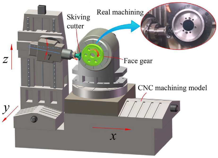
The gear skiving machining model is shown in Figure 1, the tool maintains a constant angle γ with the x-axis, and feeds along this axial direction for cutting, the face gear and skiving cutter makes continuous indexing rotation. Under the action of forced meshing with the tool, the face gear is processed. The skiving cutter feeds along the y-axis direction to gradually complete the machining of the gear tooth profile.
Schematic diagram of gear skiving.
Gear skiving is an efficient gear processing method, which is similar to gear shaping and has the motion state of gear hobbing at the same time. The skiving movement is shown in Figure 2, in which the skiving cutter is helical bevel gear structure, and the helix angle is β, the initial offset distance between the rotation axis of the skiving tool and the center line of the face gear is H, the initial cutting point is P1, and the final cutting point is P2, vs and v2 are the linear velocity vector of the skiving tool and the face gear at the initial cutting point respectively, and vs2 is the relative motion speed of the skiving tool along the extension direction of the tooth profile of the face gear. During machining, the offset distance is continuously adjusted so that the cutting edge of the tool is always tangent to the tooth profile of the face gear at the machining point. The skiving tool and the face gear rotate at the angular speed ws and w1 speed and the skiving tool feeds along the face gear tooth direction, and finally completes the face gear machining. The relationship between the angular velocities ws and w1 of the cutter and the face gear is shown in equation (1), where ns and n2 are the number of teeth of the skiving cutter and the face gear respectively.
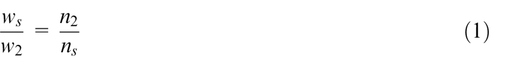
Schematic diagram of the skiving movement.
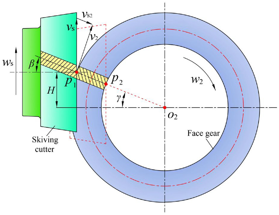
The gear skiving process is shown in Figure 3. The position of the tool relative to the workpiece is 1–2–3–4–5 in turn. The cutting starts from the tooth root of the cutting edge and moves towards the top of the face gear as the cutting proceeds, as shown in position 2; The cutting point starts the processing of the tooth root at position 3. After the tooth root processing is completed, the gear skiving tool exits the meshing, and the tooth profile of the face gear is gradually formed under the forced meshing and cutting movement of the gear skiving, and finally the cutting is finished. 11
Schematic diagram of skiving process.
Design method of face gear tooth profile
Establish tooth surface generating coordinate system
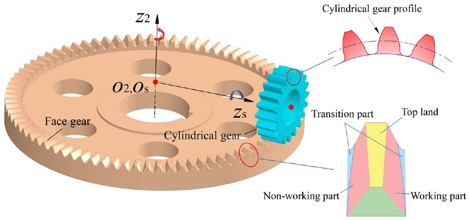
Figure 4 is a coordinate system established according to the tooth surface generation principle, includes motion coordinate systems SS-Osxsyszs, S2-O2x2y2z2 and fixed coordinate systems Ss0-Os0xs0ys0zs0, S20-O20x20y20z20. The coordinate system Ss and S2 are connected with the cutter and the face gear, Ss0 and S20 are the rack coordinate system.
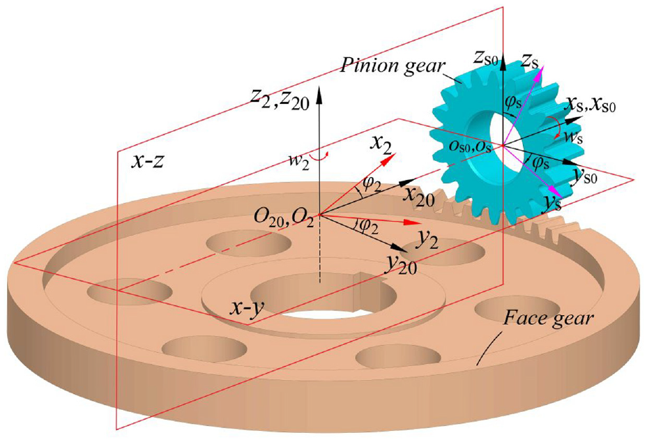
Tooth surface generating coordinate system.
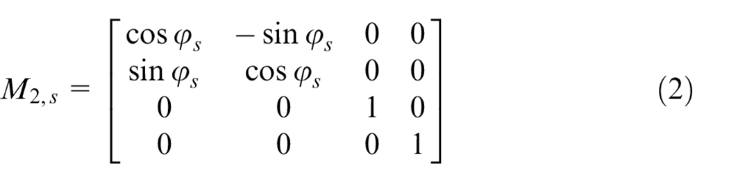
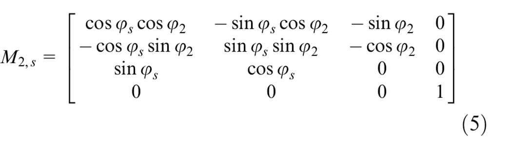
The coordinate transformation matrices were introduced to transform the tooth surface of the pinion from Ss to S2. The matrix Ms0,s describes the transformation of the motion coordinate system SS-Osxsyszs of pinion to its fixed coordinate system Ss0-Os0xs0ys0zs0.
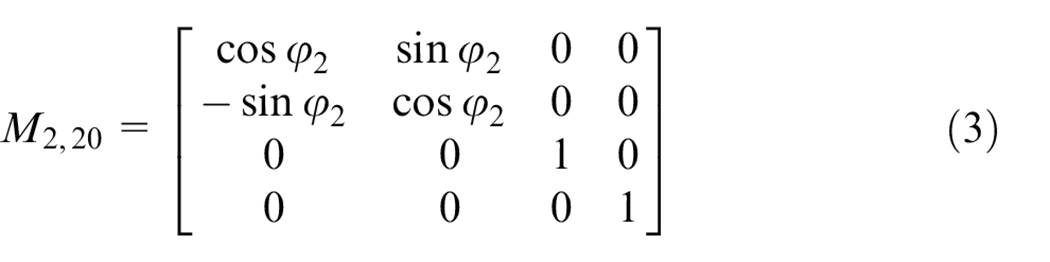
The matrix M2,20 describes the transformation of the face gear fixed coordinate system S20-O20x20y20z20 of pinion to its motion coordinate system S2-O2x2y2z2.
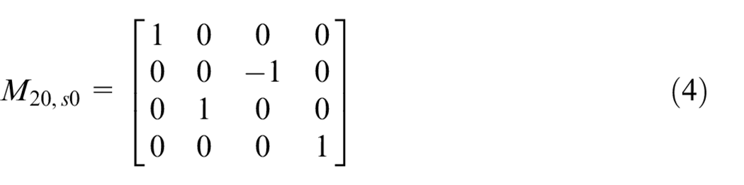
The matrix representing the transformation from the transformation from Ss0-Os0xs0ys0zs0 to S20-O20x20y20z20 can be expressed as M20,s0, and the transformation from SS-Osxsyszs to S2-O2x2y2z2 can be expressed as M20,s0.
Cylindrical gear tooth surface equation
The face gear tooth surface can be regarded as the result of the conjugate generation of the pinion gear tooth surface. The involute tooth profile of the pinion gear is shown in Figure 5. The pinion gear tooth surface equation rs(us, αc) as shown in formula (1).
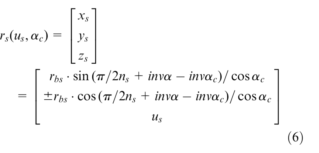
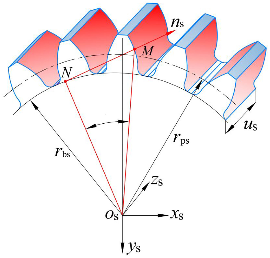
Schematic diagram of pinion gear profile tooth.
Let αs = π/2ns+invα−invαc, the normal vector can be expressed as:
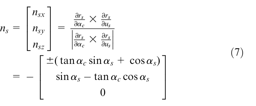
Meshing equation of face gear
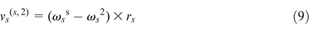
Figure 6 is the tooth surface of face gear, which the surface equation can be obtained by the coordinate transformation and meshing principle as formula (3). In the formula, vs(s,2) is the relative speed of the face gear and the pinion gear.
Tooth surface model of face gear.
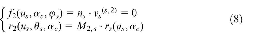
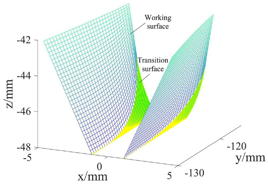
Bring the normal vector and relative velocity into the meshing equation, the formula rs (us, θs) satisfying the condition is solved according to equation (8). Through coordinate transformation, the face gear surface can be obtained. The face gear has a transitional surface that does not participate in engagement as show in figure 7, which is generated by the pinion top-line sweep, the transition surface can be obtained by restricting the parameter αc to the addendum circle.1–3
Schematic diagram of face gear transmission.
Parameter calculation of gear skiving cutter
Mathematical model of conjugate surface
Similar to other gear cutting tools, gear skiving cutter has the structural elements such as rake face, flank, top edge, main edge, and so on.
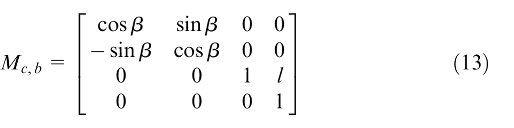
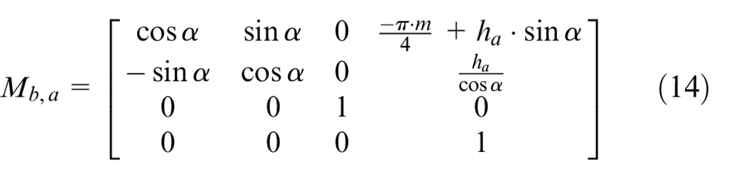
The structure of the gear skiving cutter is helical bevel gear, this paper deduces the tooth surface of the skiving cutter from the rack cutter. Figure 8 is a schematic diagram of the tooth profile of the rack cutter. In the coordinate system Sa, the rack tool tooth profile can be expressed as ra = [u2u l 0]T. Where u is the distance from the cutting point to the origin Oa, and l is the rack cutter tooth direction position parameter. The tooth profile equation and normal vector of rack cutter are expressed in the coordinate system Sc as follows. 24

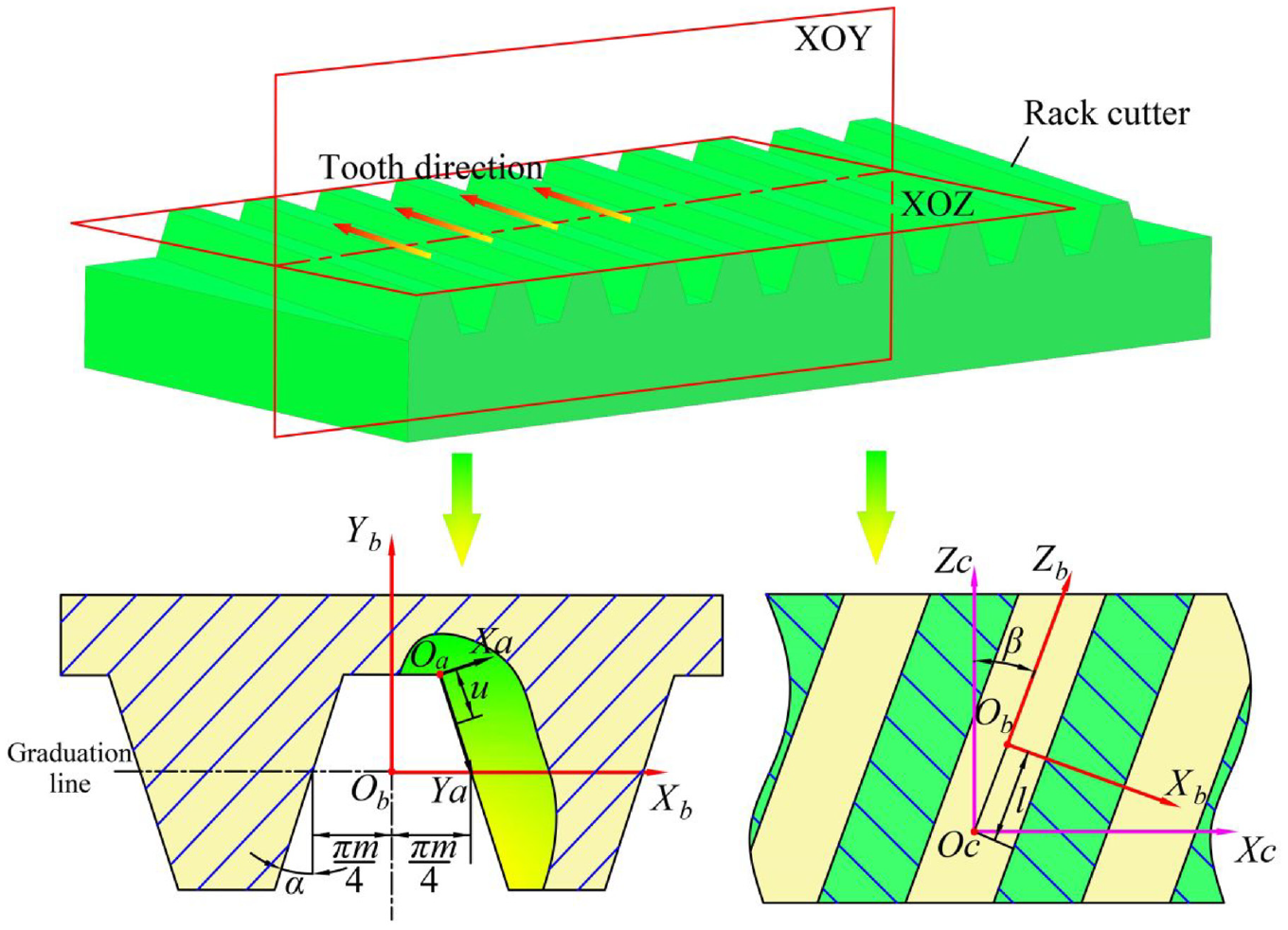
Tooth profile diagram of rack cutter.
Where, Mba is the transformation matrix from coordinate system Sa to coordinate system Sb, and Mcb is the transformation matrix from coordinate system Sb to coordinate system Sc.
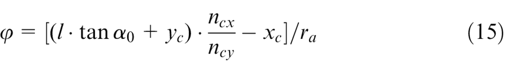
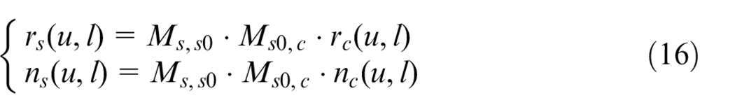
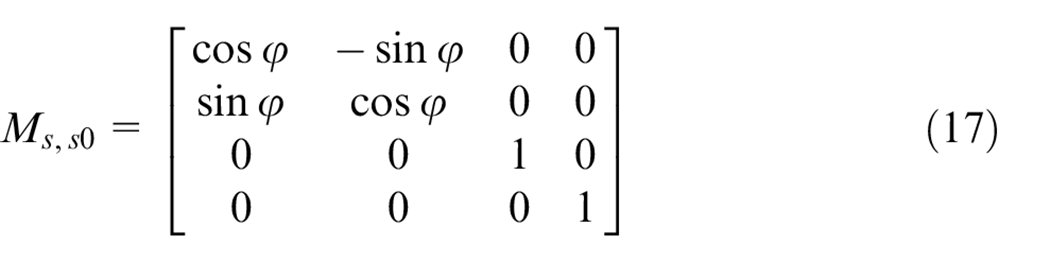
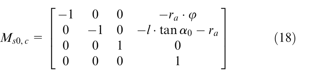
Figure 9 shows the coordinate system of the rack cutter for machining the skiving cutter, Sc is the rack cutter reference coordinate system, Ss0 is the gear skiving cutter reference coordinate system, Ss is the gear skiving cutter moving coordinate system, l·tanα0 is the displacement at different tooth direction positions of rack cutter. According to the involute gear generating principle, the corresponding rack moves ra·φ along the pitch line. The meshing condition of the gear skiving cutter deduced from the rack cutter is that the connecting line between any point on the cutting edge of the rack cutter and the instantaneous center I is the normal direction of the cutting point, that is, the angle of rotation φ satisfy the equation (15). The tooth surface position vector rs and normal vector ns of the skiving cutter in S2 are:
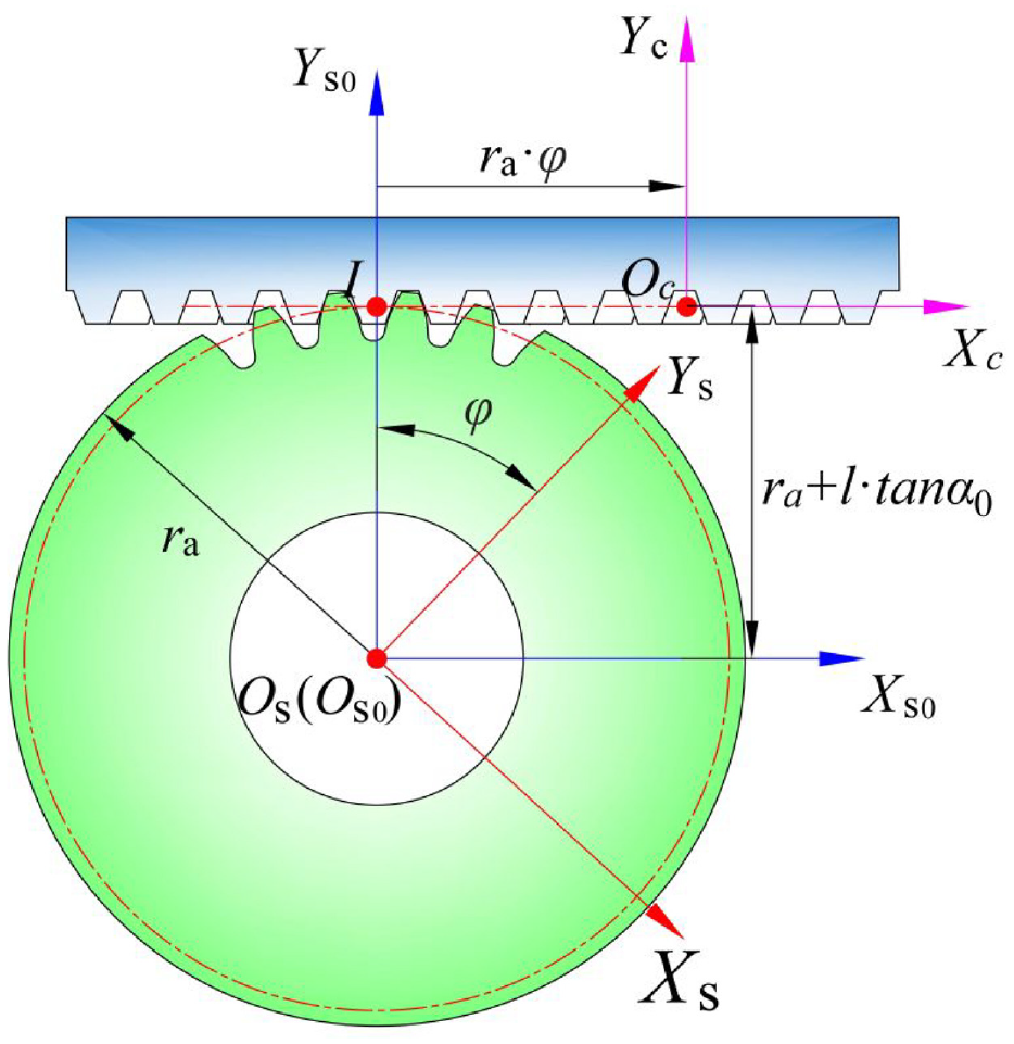
Coordinate system of gear skiving tool for rack cutter machining.
Where Ms,s0 are the transformation matrix from coordinate system Ss0 to coordinate system Ss, Ms0,c are the transformation matrix from the coordinate system Sc to the coordinate system Ss0, and ra is the radius of the workpiece pitch circle, φ is the rotation angle of the gear skiving tool.
The NURBS surface has good local control characteristics, to fit the value points of the conjugate surface with NURBS surface, it is necessary to calculate the given control vertices. The inverse calculation problem of the surface is usually resolved into two-stage curve inverse calculation, select M × N type value points on the conjugate surface, suppose the type value point of the j-th (j = 1, 2, …, N) u-direction curve is Fi,j, the control points are Vi,j (i = 1, 2, …, M+2), then the equations of the j-th control point are as follows 20 :
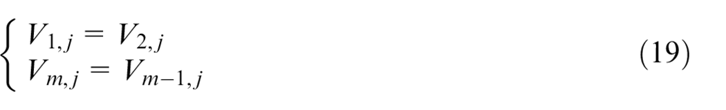
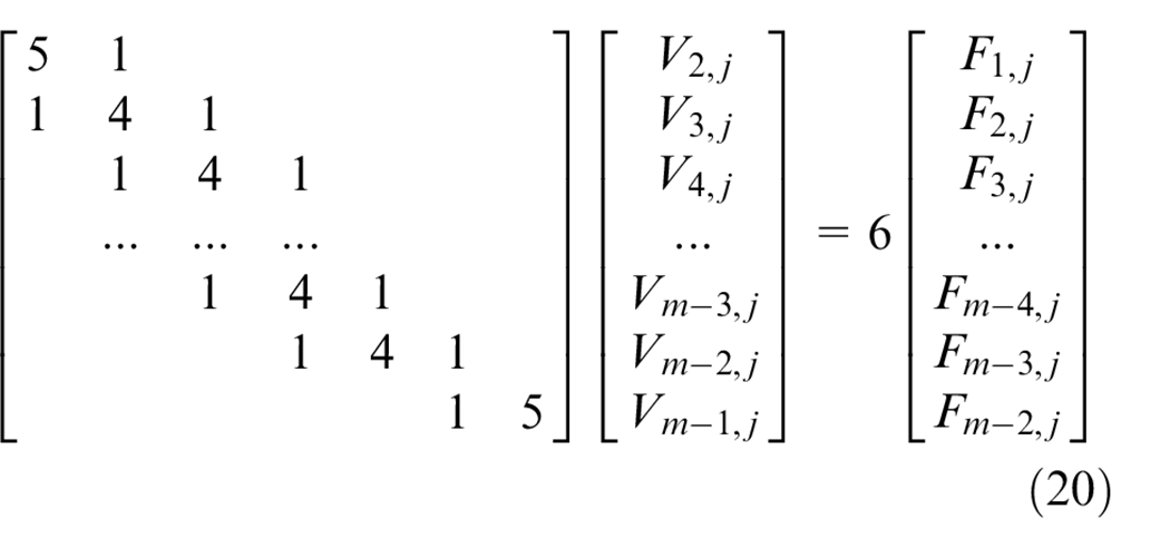
According to the free endpoint condition (19), the control point in u-direction can be obtained, take the u-direction control point as type value point in w-direction, and calculate the B-spline surface control point pi,j in the same way, the parameters u and w and the control points Pi, j constitute the B-spline surface fitting equation, as shown in formula (21), Figure 10 is the schematic diagram of fitting tooth surface.
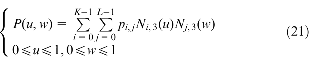
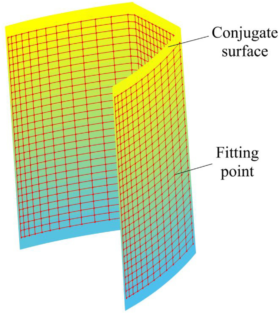
B-spline fitting conjugate tooth surface.
Model of rake face
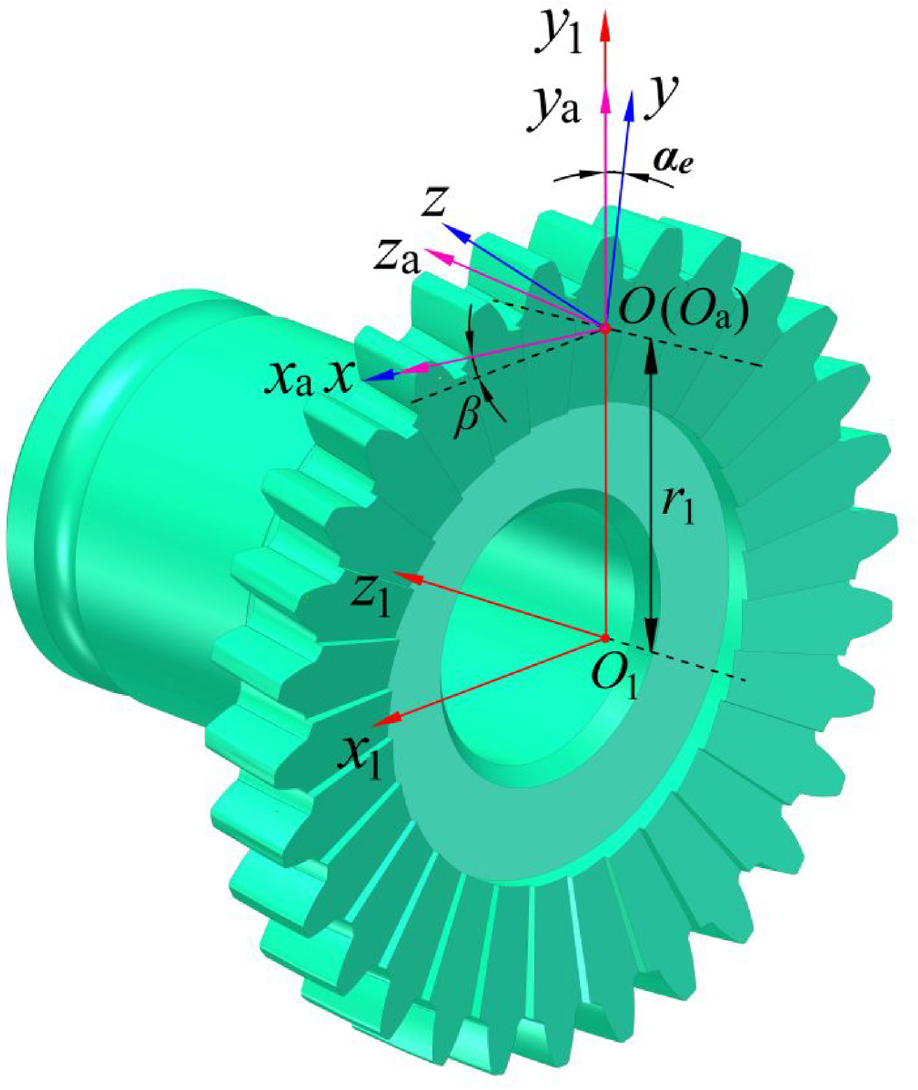
In the process of gear skiving, there is an angle between the tool and the workpiece during processing. The plane inclined to a certain angle with the end face is used as the rake face to make the cutting angles of the two edges of the gear skiving cutter close, and reduce the edge error of the gear to be processed. In Figure 11, the coordinate system Ss-Oxyz is the rake face coordinate system, Sa-Oaxayaza is the auxiliary face coordinate system, S1-O1x1y1z1 is the tool motion coordinate system, the rake face normal vector can be expressed as n(0, 0, 1) in the coordinate system S. The rake face normal vector in S1 can be expressed as n1(cosβsinαe, −sinβ, cosβcosαe) according to formula (22).

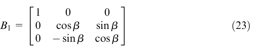
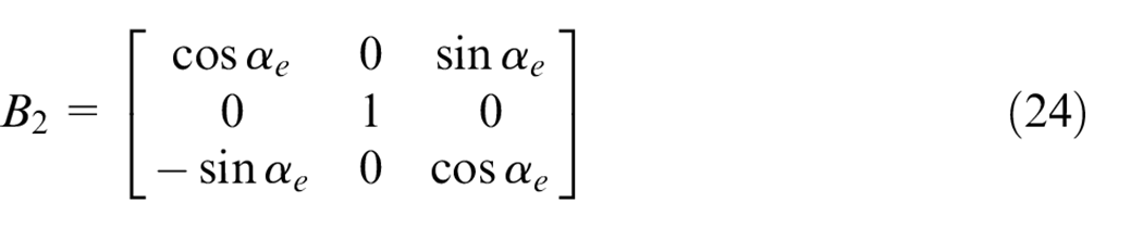
Where αe is the rake angle of the tool, β is the tool helix angle, B1 is the matrix of the transformation from the rake surface coordinate system Ss to the auxiliary surface coordinate system Sa, B2 is the matrix of the transformation from the auxiliary surface coordinate system Sa to the tool motion coordinate system S1, the rake face equation in S1 is shown in formula (25):
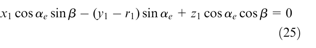
Skiving cutter rake face coordinate system.
Model of cutting edge
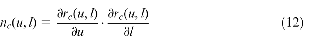
The solution of the skiving cutting edge curve based on the conjugate principle is equivalent to the solution of the intersection of two curved surfaces. The conjugate surface are fitted by NURBS surface, where x1 = P1(u, w), y1 = P2(u, w), z1 = P3(u, w), the rake surface equation can be expressed as f(x1, y1, z1) = 0, and the intersection equation between conjugate surface and rake surface can be expressed as f(P1(u, w), P2(u, w), P3(u, w)) = P(u, w) = 0. In this paper, the distance between the point cloud and the rake surface is approximated by the Newton iteration method to obtain the main cutting edge. Divide u and w into n parts, The spacing of each grid on the fitted conjugate surface is Δu = Δw = 1/n, the vertices of the rectangular unit Δij in the equation P(u, w) correspond to the function values P(ui, wj), P(ui, wj+1), P(ui+1, wj), P(ui+1, wj+1). The solution flow of cutting edge is shown in Figure 12, and the main cutting edge calculation steps are as follows21,22:
(I) Bring the components x2=P1(u,w), y2=P2(u,w), z2=P3(u,w) of the vertices of the mesh in the fitting point cloud into f(x2, y2, z2) and judge the symbol of the vertices of each mesh (greater than 0 is recorded as “+,” otherwise it is recorded as “−”).
(II) Judge the calculation results of (I), if the vertices of the conjugate surface mesh unit have the same sign, there will be no intersection with the rake face. Otherwise, execute item (III).
(III) For element edges with different signs, use Newton iteration to calculate the intersection point. For the element edge (wj, wj+1), let P(ui+1, wj+1) be “−,”P(ui+1, wj) be “+,” and ut = ui+1, wt is solved by Newton’s iterative formula (26).
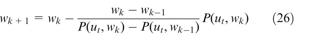
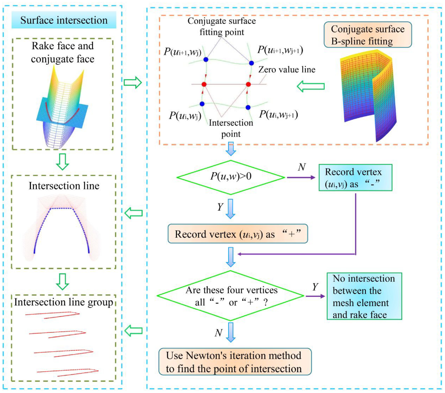
Schematic diagram of surface intersection.
Set the iteration accuracy ξ = 0.001, when equation (26) is iterated to wk+1−wk < ξ, wt = wk+1 can be solved. Calculate the corresponding u and w values and substitute them into x1, y1, and z1 to obtain the intersection point. The characteristic points of other series on the main edge can be calculated in the same way.
Figure 13 is the schematic diagram of solving the cutting edge curve when the rake face intersects with the tool tooth surface. The cutting edge curve in the figure is the intersection line between the rake face and the tool tooth surface, and the envelope curve is the intersection line between the rake face and the rack tool envelope surface.
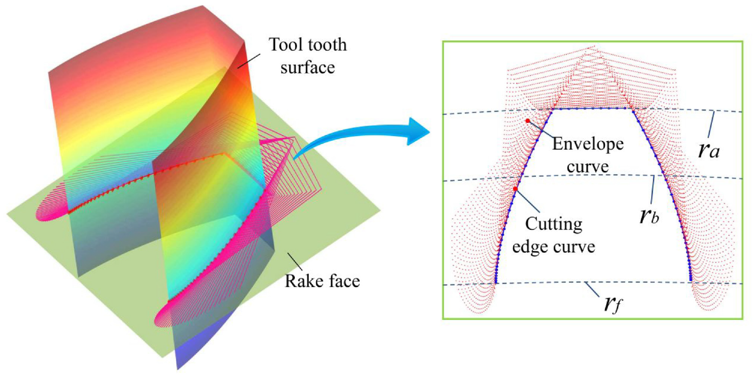
Schematic diagram of cutting edge envelope solution.
Three-dimensional model design of face gear skiving cutter
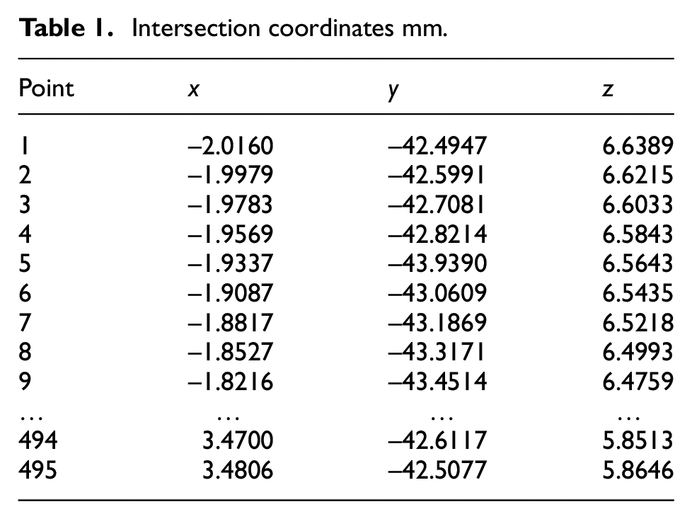
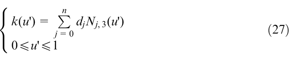
The design flow of three-dimensional model of gear skiving tool is shown in Figure 14, refer to section 3.2 to obtain the rake face equation; Let the modulus m = 3 mm, number of teeth n2 = 90, shaft angle γ = 5° to calculate the conjugate surface point and fitted with the NURBS surface; The number of cutter teeth n1 = 31, part of the intersection data is shown in Table 1, fit the intersection point according to formula 27 to get the cutting edge:
Intersection coordinates mm.
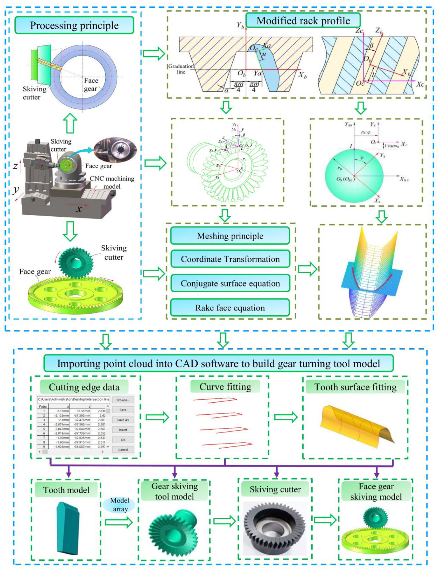
Gear turning tool design process.
Import the cutting edge point cloud fitted with the B-spline curve into the CAD software, and build a single tooth model through surface stitching function, and array single tooth to obtain the skiving cutter model.
Tooth surface model and error analysis of face gear skiving
Tooth surface model of face gear skiving
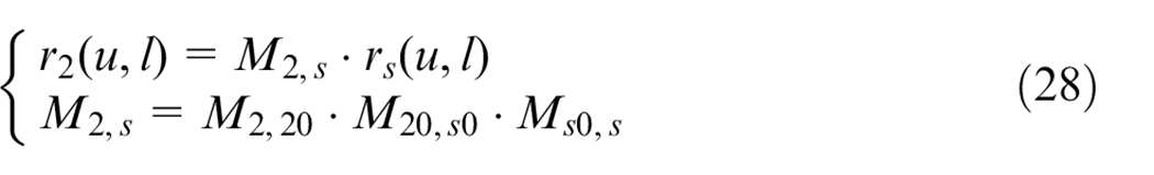
Figure 15 is the gear skiving coordinate system established according to the tooth surface generation principle, in which Ss-Osxsyszs is the tool motion coordinate system, S2-O2x2y2z2 is the face gear motion coordinate system, Ss0-Os0xs0ys0zs0 is the tool reference coordinate system, and S20-O20x20y20z20 is the face gear reference coordinate system. φ2 is the rotation angle of the face gear, φs is the rotation angle of the skiving cutter, r is the distance between the center point of the face gear and the center point of the skiving cutter, γ is the axis intersection angle. The envelope equation of face gear skiving tooth surface is as follows:
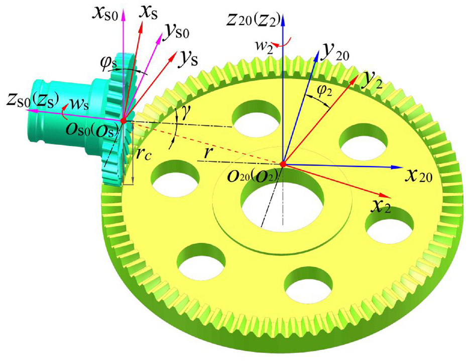
Gear skiving coordinate system.
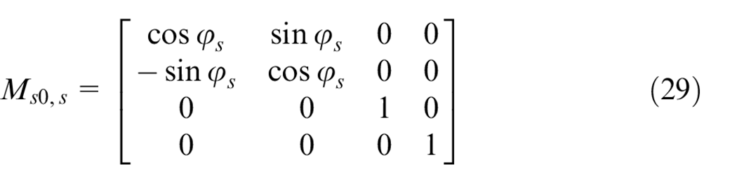
The coordinate transformation matrices were introduced to transform the tooth surface of the skiving cutter from Ss to S2. The matrix Ms0,s describes the transformation of the tool motion coordinate system SS-Osxsyszs to its fixed coordinate system Ss0-Os0xs0ys0zs0.
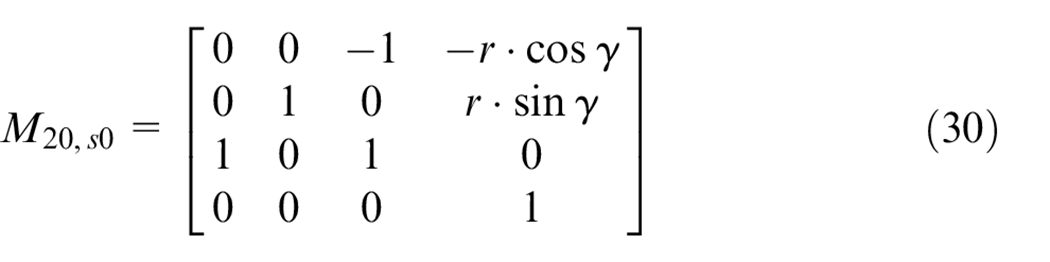
The matrix M20,s0 describes the transformation of the tool reference coordinate system SS0-Os0xs0ys0zs0 to the face gear reference coordinate system S20-O20x20y20z20.
The matrix M2,20 describes the transformation of face gear reference coordinate system S20-O20x20y20z20 to the face gear motion coordinate system S2-O2x2y2z2.

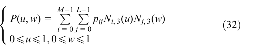
Starting from the working principle of skiving, in the coordinate system shown in Figure 15, change the rotation angle φs of the skiving tool and the tooth feed amount r, Constitute cutting edge point cloud for different feeds, extract the continuous tooth surface enveloping line and finally constitutes the enveloping tooth surface of the face gear, 25 as shown in Figure 16. The extracted point cloud is fitted with NURBS surface, and equation (32) is the surface fitting equation.
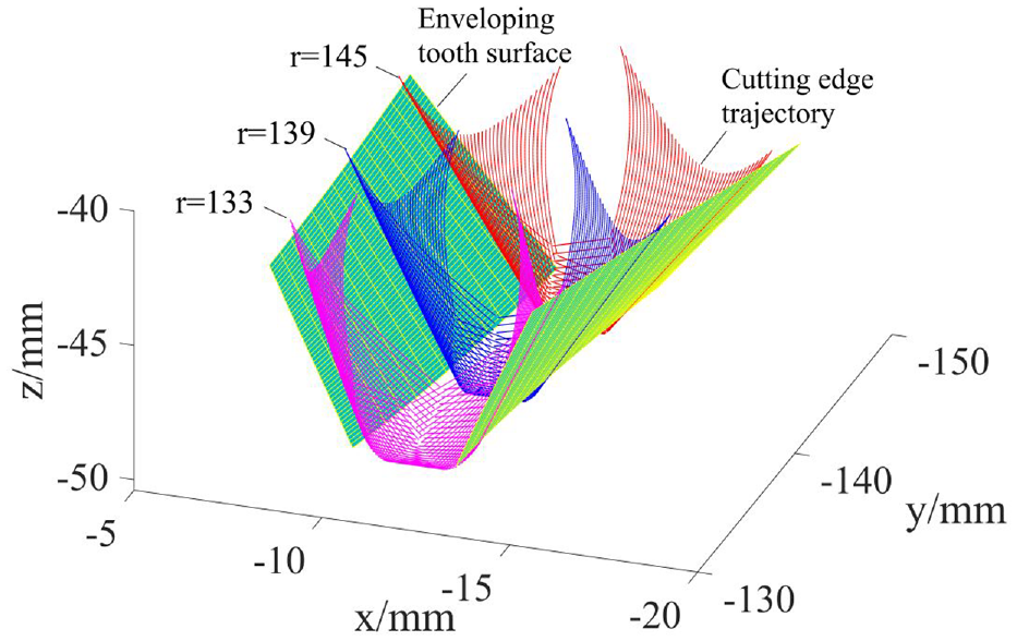
Schematic diagram of enveloping cutting edge.
Tooth surface error analysis of face gear skiving
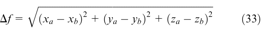
Only when the cutting edge is consistent with the standard tooth profile, the face gear tooth surface has no theoretical error. However, after tool grinding, due to the existence of the rake angle and the relief angle, the projection of the cutting edge on the base surface is not involute, which results in tooth profile error.13–16 In Figure 17, the red part is the actual tooth profile shape, the tooth profile of section I-I is the standard tooth profile. The cutting edge can be obtained by intersecting the conjugate surface and rake surface according to section 3.3, record the actual tooth profile equation as f(xa, ya, za) = 0, and the standard tooth profile I-I can be obtained by limiting the displacement l·tanα0 = 0 in the conjugate surface equation (16), record it as f(xb, yb, zb) = 0. The calculation formula of tool tooth profile error is shown in equation (33).
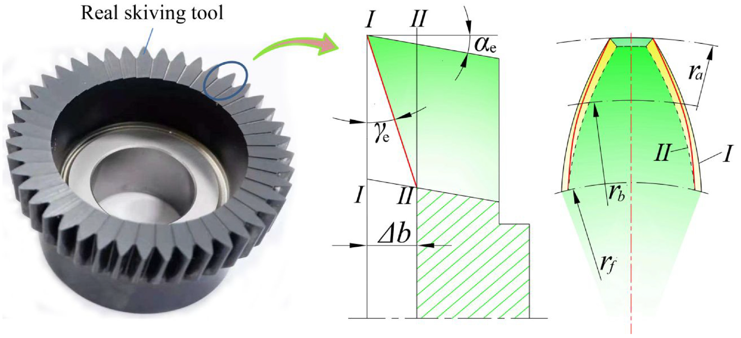
Schematic diagram of cutting edge error.
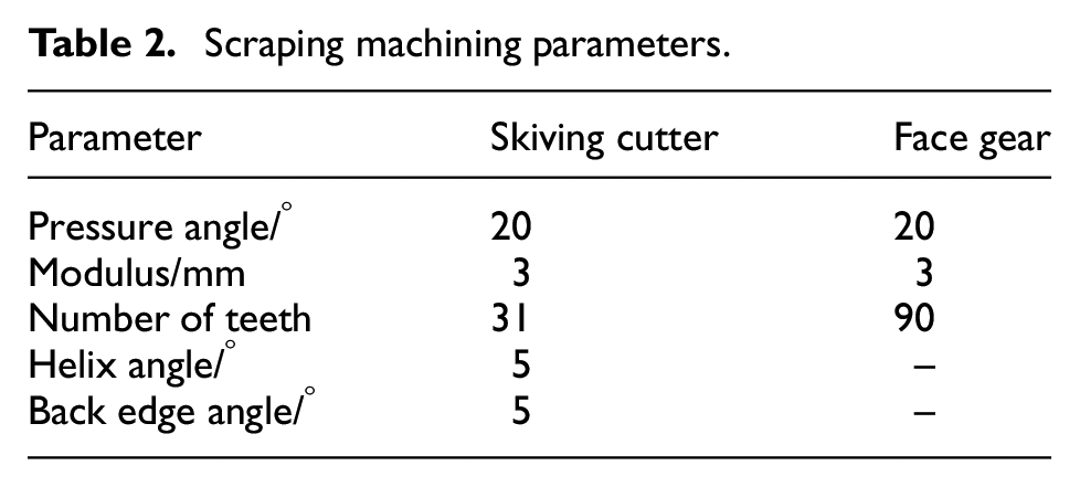
Table 2 shows the specific parameters of gear skiving. According to the content of Section 3.3, solve the point cloud of the cutting edge corresponding to different front and rear angles and analyze the error. Figure 18(a) and (b) shows the tooth profile deviation corresponding to different rake angles. It can be seen from the figure that the tooth profile error gradually increases from the tooth top to the tooth root, and increases with the value of the tool rake angle. When the front angle αe = 6° and the back angle γe = 5°, the maximum error value of the left tooth profile is about 23 µm and the maximum error value of the right tooth profile is about 20 µm. The errors on both sides of the tooth profile are different, this is due to the asymmetric projection of the tooth profiles on both sides on the front face.
Scraping machining parameters.
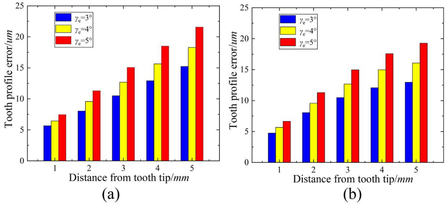
The skiving cutter tooth profile error: (a) left tooth profile error and (b) right tooth profile error.
Let the rake angle αe = 0° and the clearance angle γe = 0°, and take the obtained tooth surface as the error-free reference tooth surface, take the front angle αe = 5° rear angle γe = 5° enveloping tooth surface as the comparison tooth surface, analysis of Cutter profile error on the error of the left and right flanks. Figures 19 and 20 is the cloud diagram of the error distribution of the left and right tooth surfaces, it can be seen from the Figure 19 that the tooth surface error of face gear increases gradually from tooth root to tooth top.
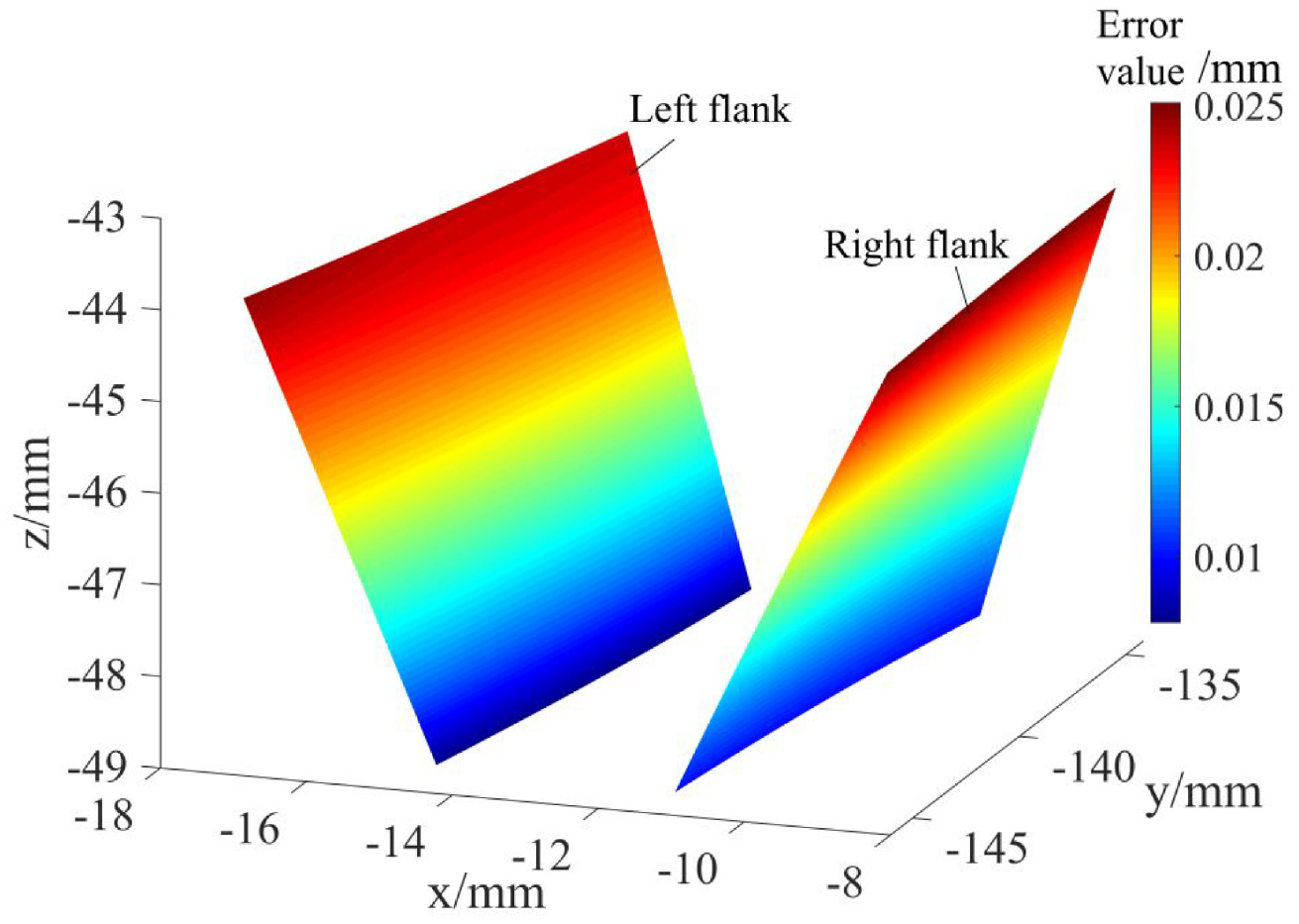
Tooth surface error without modification.
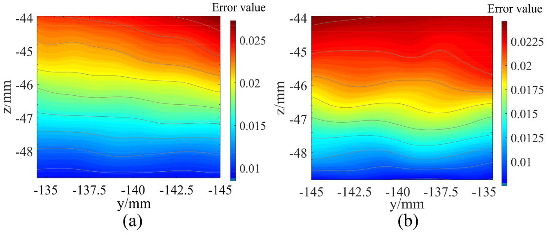
Tooth surface error diagram: (a) error diagram of left tooth surface and (b) error diagram of right tooth surface.
It can be seen from Figure 20(a) and (b) that the maximum error of the left tooth surface is about 26 μm, and the maximum error of the right tooth surface is about 23 μm.
Conclusions
(1) A new face gear processing method is proposed in this paper. According to the principle of surface generation, change the traditional cutting and machining motion mode, design high-precision skiving cutter to process face gear, which can realize continuous and efficient processing of face gear.
(2) According to the meshing principle and the structural characteristics of skiving cutter, constructed the coordinate system to solve the conjugate and rake surface models; The intersection of rake surface and conjugate surface is solved by Newton iterative method, fit the intersection data and import it into CAD software to construct a mathematical model of skiving tool, and the enveloping tooth surface of cutting edge in skiving machining is solved according to the envelope method, which further improve the design theory of gear skiving.
(3) There are errors in the tooth profile of the gear skiving tool due to the front angle and back angle, and the error increases gradually from the tooth top to the tooth root. The tooth profile error of the gear scraping tool has an impact on the tooth surface of the face gear, which makes the tooth surface error of the face gear increase gradually from the tooth root to the tooth top.
Footnotes
Appendix
Declaration of conflicting interests
Shuai Mo and Saisai Wang contributed equally to this manuscript, they are co-first authors of the article. The author(s) declared no potential conflicts of interest with respect to the research, authorship, and/or publication of this article.
Funding
The author(s) disclosed receipt of the following financial support for the research, authorship, and/or publication of this article: This research is financially supported by National Key Laboratory of Science and Technology on Helicopter Transmission (No. HTL-0-21G07), Open Fund of State Key Laboratory of Digital Manufacturing Equipment and Technology, Huazhong University of Science and Technology (No. DMETKF2021017), Interdisciplinary Scientific Research Foundation of Guangxi University(No.2022JCC022), National Natural Science Foundation of China (No. 51805368), Young Elite Scientists Sponsorship Program by CAST (No. 2018QNRC001), Entrepreneurship and Innovation Talent Program of Taizhou City. Jiangsu Province.