
Abstract
The interference fit has been widely used for torque transmission and assembly stability in the modern machinery industry. The form error of cylindrical feature is propagated during the interference fit of shaft-hole assembly, which causes the translation and rotation of following structures. Therefore, the overall precision variation is difficult to be predicted. In this paper, an error computational model of interference fit stage is proposed to represent the form error propagation of cylindrical features in the shaft-hole assembly. The characteristic parameter of form error is obtained by the minimum zone cylinder method and integrated into the small displacement torsor. The deformation behavior of interference fit with form error is described as a weakening propagation of error. An interference fit error propagation coefficient is introduced to quantify the phenomenon of weakening propagation of error, which depends on particular fit conditions such as materials, sizes, and interference range of parts. The error computational model for interference fit with form feature is deduced by using the Jacobian-Torsor theory. The characteristic of deformation flexibility in the interference fit is well considered comparing to the simple rigidity analysis in the traditional Jacobian-Torsor model. An error analysis of a shaft-hole structure deciding the symmetry and sensibility performance in the servo valve is conducted to verify the applicability. The cylindrical feature error and deformation during the interference fit are included. The results show that the new error model may represent characteristics of interference fit error propagation with form feature and has a higher reliability than the traditional error models.
Keywords
Introduction
The shaft-hole structure with interference fit is widely used in the modern machinery industry. Predicting the interference fit precision of shaft-hole assembly is important in the design and manufacturing phases. The key of analysis is the flexible deformation existing in the shaft-hole cylindrical surfaces during interference fit. The computational models for assembly error in existing literatures neglect the flexible error source of interference fit. The traditional theoretical models for interference fit processes well describe the fit deformation, but the applicability is restricted by the materials, sizes, interference ranges and these models are unable to take the form error into account. The two-dimensional linear chain is a typical method but it’s hard to represent the error propagation of three-dimensional (3D) displacement and rotation. The direct linearization method constructs the assembly chain with 3D vectors with great difficulty and complexity, which is incompatible with engineering planar drawing and has ambiguity in the definition of errors for rotational and cylindrical features. The finite element method is also used to calculate the feature deformation of interference fit with form error. However, the modeling of object with manufacturing errors requires considerable techniques and the numerical model is inefficient in calculating, which makes it difficult to conduct the statistical analysis of products. The Jacobian-Torsor method uses the torsor model for error representation and the Jacobian matrix for error propagation, but this rigid model fails in describing the influence of interference fit with form error. Therefore, a new computational model of error propagation is necessary to precisely and effectively calculate the interference fit error with form feature in the shaft-hole assembly.
The interference fit structure is widely studied in the field of mechanical assembly. The performance of fit structure is directly decided by the mechanical behavior of fitting features. Yang et al. 1 studied the influence of the roughness of interference fit surfaces on the fitting strength and determined the behavior of contact surface with the press force effect of interference fit assembly. Baldanzini 2 established a theoretical model of interference fit connection based on the elastic-plastic hypothesis of materials. Lewis et al. 3 proposed a method for measuring the contact stress of interference fit surfaces and studied the contact stress distribution on different fitting surfaces. Kiral 4 studied the influence of interference fit joint size on the structural failure mode and bearing capacity of the fitting structure. Jiang et al. 5 numerically simulated the interference fit assembly process of mechanical joints and studied the change of stress characteristics of fitting surfaces with different assembly parameters. Pedersen 6 changed the size and shape of the hole parts to improve the pressure distribution of the contact surface after interference fit assembly. Liu et al. 7 studied the stress and strain characteristics of bearing and shaft after interference fit. Wang et al. 8 established a mechanical model of shaft-hole interference fit based on the non-uniform linear load theory. Cylindrical features with error in shaft-hole structures are also paid great attention in recent researches. Liu et al. 9 optimized the assembly process of cylindrical multistage rotors by analyzing the mass eccentricity deviation. Korbi et al. 10 utilized finite element method to obtain point clouds of deformed planar faces and cylindrical faces. Mu et al. 11 researched the manufacturing error of mating end face of circular feature in rotor systems. Liu et al. 12 designed a cylindrical profile measurement model comprising seven systematic parameters of errors. These researches have improved the theoretical models of mechanical behavior of shaft-hole interference fit and provided solutions for stress-strain calculation and the part selection in various fit conditions. However, the existing researches lack of the manufacturing error on the interference fit surface of the shaft-hole assembly. The irregular form error on the fitting surface may affect the structural consistency in the mass production.
The Jacobian-Torsor theory is an interesting work for mechanical assembly error. Clément13,14 introduced the torsor model for the representation of displacement and rotation variations of feature surfaces in the 3D zone. Combined with a small displacement variation matrix, the torsor representation of feature variations could be accumulated linearly. 15 Lafond 16 introduced the concept of virtual joint and Jacobian matrix to express the relative location between feature surface and target point. The Jacobian-Torsor model was proposed by Desrochers, 17 which combined the torsor model representing the tolerance zone and the Jacobian matrix expressing the position propagation. Laperrière 18 proposed the extreme value calculation method and statistical calculation method of error propagation by considering the spatial boundary of the tolerance zone based on the Jacobian-Torsor model. Ni and Yao 19 integrated the cylindricity into the Jacobian-Torsor model to study the influence and accumulation of cylindricity error on the actual structure of clearance fit. Chen et al.20,21 adopted a set operation to integrate the partial parallel variation of cylinder-plane feature into the Jacobian-Torsor model, enabling the special structure to participate in the calculation of error accumulation. Zeng et al. 22 used the worst-case tolerance analysis method to study the cylinder-cylinder partial parallel feature based on the Jacobian-Torsor theory. Jin et al. 23 proposed a measurement point-based method to express feature error based on the Jacobian-Torsor model, which was suitable for a small sample number of assembly error analyses with partial parallel features. Du et al. 24 applied the Jacobian-Torsor model to the single-axis assembly, in which the partial parallel connection of features is considered. Kang and Li 25 integrated the numerical simulation result of partial flexibility structures into the Jacobian-Torsor model and realized the error analysis with partial flexibility structures in the bolt fastening. Ding et al. 26 considered the part characteristics of multi-axis rotors to establish an improved Jacobian-Torsor model that was applied to aero-engine rotor assembly. Current studies continue to improve the availability of the Jacobian-Torsor theory, but few studies emphasize on error propagation of the interference fit stage. The interference fit stage is characterized by cylindrical form error propagation and flexible deformation. The flexible characteristics make it difficult to represent and calculate the interference fit error using the traditional Jacobian-Torsor theory.
In this study, a new error computational model is proposed for the shaft-hole interference fit with form features. The weakening phenomenon of error propagation during the flexible deformation of interference fit is quantified. Cylindricity is evaluated by the minimum zone cylinder method and represented by small displacement torsor to integrate into the Jacobian-Torsor method. The form error propagation in the shaft-hole interference fit is explained. An error propagation coefficient is introduced to measure the flexible deformation of cylindrical fit surfaces according to the geometrical relationship. Numerical and experimental methods for getting the error propagation coefficient of a particular object are proposed. The computational model of error propagation is built to include the form error and interference fit conditions, such as materials, sizes, and interference range of the assembly. An example of shaft-hole structure in the servo valve with interference fit is conducted to verify the computational model.
Representation of cylindrical features with the Jacobian-Torsor method
The assembly characteristic of jet-disk in the servo valve is illustrated in Figure 1. The manufacturing precision of the jet-disk assembly directly decides the serve performance of the servo valve which is used in the fuel control of spacecraft engines. The assembly of jet-disk could be regarded as a shaft-hole structure. The upper end cover is conducted with press force to fit into the hole of the base, and the lower end cover located at the bottom of the hole is a clearance fit with the hole of the base. The position of clearance between the upper end cover and the lower end cover is the key of the working performance of product. For realizing the key parameter prediction, the manufacture errors of different parts of jet-disk are considered to derive the displacement error and the rotation error of the target feature.
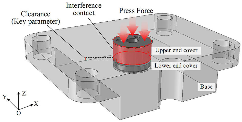
The jet-disk assembly in the servo valve.
The variation range of the size and form during the manufacture of part is denoted as the tolerance zone. Figure 2(a) shows the tolerance zone of end faces in the jet-disk assembly. Here, O-XYZ is the global coordinate system. The nominal position of feature surface and any point in it are defined as
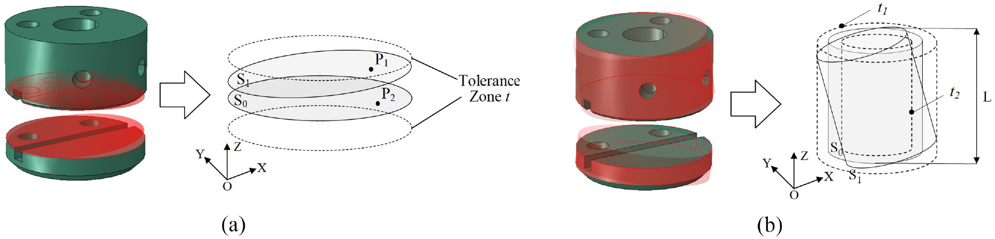
The tolerance zone of jet-disk assembly: (a) end faces, (b) cylindrical features.
The variations of the error surface compared with the nominal surface are divided into the displacement and rotation components, which are expressed as
where
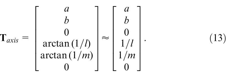
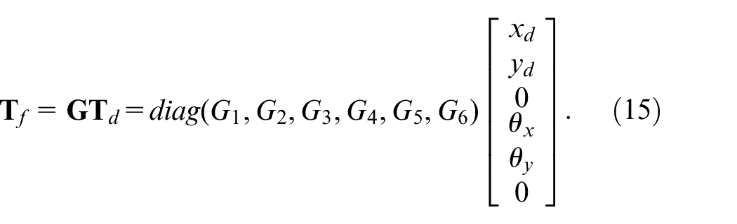
According to the variation range of the cylindrical feature, the displacement and rotation components exist in the X, Y directions. The torsor of cylindrical feature is expressed as

The cylindrical surface and any point in it are restricted in the tolerance zone. The restriction of locations could be expressed as
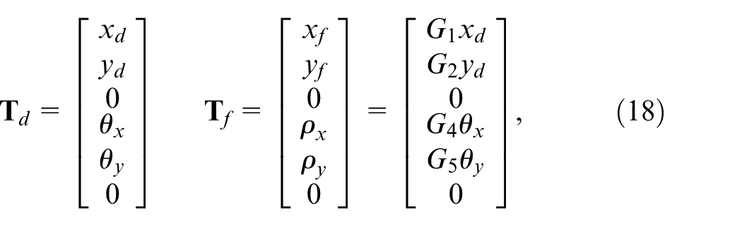
The manufacture error propagation is a small quantity comparing with the size of object. So the Jacobian matrix could be divided into two parts. The first part represents the propagation of the feature surface displacement and the second part represents the propagation of the feature surface rotation. The Jacobian matrix of error propagation is expressed as
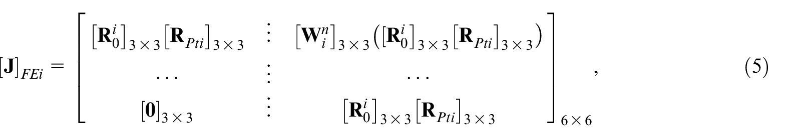
where the first three rows represent the displacement components and the last three rows represent the rotation components. For the error calculation of target points in the global coordinate system, the direction of error torsor in the local coordinate system is transformed by a matrix. The direction transformation matrix

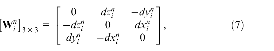
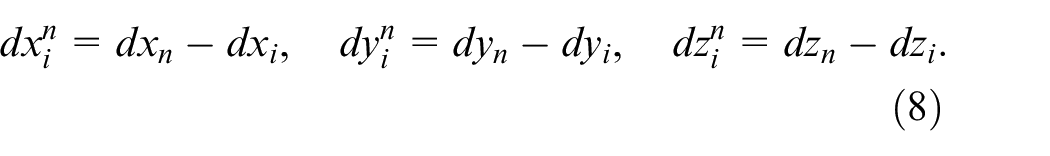
The leverage effect exists in the propagation of rotation errors and can be expressed by the cross product of the rotation vector and the distance vector. The distance vector represents the vector from the feature point to the target point. The operation of cross product could be integrated into a matrix
Furthermore, the projection matrix
Propagation coefficient-based solution of interference fit
Representing of cylindrical form variation
The position and orientation of the shaft-hole assembly are influenced by form features of cylindrical surfaces in the interference fit procedure. The manufacturing errors are propagated to the following structures through the leverage effect. Cylindrical form error defines the maximal and minimal form variations, quantified as cylindricity. In Figure 3(a), the irregular cylindrical form errors are fitted to concentric standard cylinders which could be represented as torsor parameters and integrated into the torsor model.
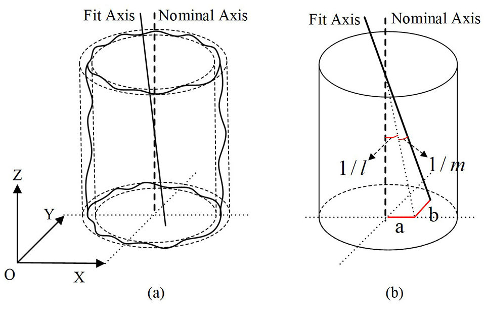
Fitting and parameterizing of cylinder: (a) the cylindrical form error and the fitting cylinder, (b) parameterization of the fitting axis error.
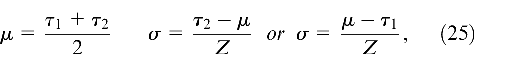
The actual irregular cylinder is fitted by the standard cylinder for the availability of error propagation computation. The minimum zone cylinder method is conducted to fit the actual cylinder with form errors by Ni et al., 27 in which two concentric cylinders are generated to cover the error variation range. When the smallest distance between two profiles of the cylinders is calculated, the collective axis of two fitting cylinders is conformed as the fitting axis. The cylindricity error of the actual cylinder is quantified by the profile distance of the fitting cylinders. The coordinates of the points in the actual cylindrical profile are expressed as
where the subscript
The distance
where

where
Description of error propagation in the interference fit
Geometric features of the shaft-hole structure with form error are analyzed. The processes of clearance fit and interference fit are illustrated in Figure 4(a). The cylindrical hole deviates from the nominal position because of the influence of form error. Considering form error far less than the size of cylindrical hole, no interference or contact existed between the cylindrical shaft and the cylindrical hole. The form error is covered in the clearance of the shaft and hole part. But the process of interference fit with the same form error differs from clearance fit. The influence of form error cannot be neglected in this fitting condition where the outside diameter of the cylindrical shaft is bigger than the inside diameter of the cylindrical hole. The push force is applied to the end face of shaft-hole structure and the deformation is accumulated in the fitting cylindrical surfaces in the procedure of interference fit.
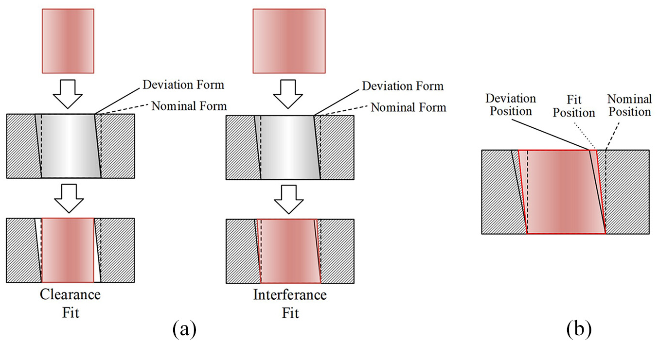
Geometric features of shaft-hole fit: (a) processes of clearance fit and interference fit, (b) different surface positions during interference fit process.
The form error of cylindrical surface of the hole part is partly propagated to the cylindrical surface of the shaft part, because of the mutual deformation in the interference process. Figure 4(b) shows the comparison of different positions in the interference fit process. The flexibility characteristic of the shaft-hole structure is considered. The final fitting surface of shaft-hole structure is located between the nominal position of the standard cylindrical surface and the deviation position of the cylindrical hole surface. The error propagation process of interference fit is demonstrated. The form error exists in the cylindrical surface of the shaft-hole structure, by which the deformation is generated during the fit of shaft and hole surfaces. Consequently, the form error from the previous stage of the assembly chain is partly propagated to the next stage, which influences the displacement and rotation of the subsequent structures after the shaft-hole structure.
Error propagation coefficient for flexible deformation of interference fit
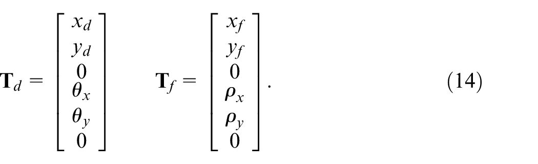
The cylindrical form error of the hole part is weakened and propagated to the shaft part through the interference fit. The variation of geometric characteristic is analyzed for the quantification of deformation during the fit. Figure 5 shows the partially larger image of cylindrical surface with form error in the interference fit process. The image is in the OXZ cross section and the axis of cylinder is along the Z direction. The deviation of original position before the interference fit is divided into displacement and rotation components, which are denoted as
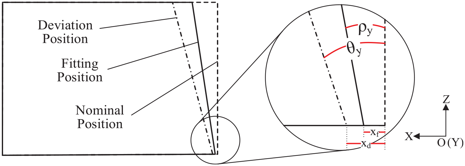
Larger image of interference fit surfaces.
The representations of the different positions in the interference fit process could be integrated into the torsor model. The position of cylindrical surface with form error before the interference fit is represented as
The variations of surfaces during the interference fit process are caused by manufacturing form error, which is a small value in relation to the size of shaft and hole cylinders. Fitting cylindrical surfaces could be supposed to deform linearly. The error propagation coefficient matrix of interference fit is introduced to characterize the weakening of the form error propagation after the interference fit. The coefficient matrix is a six-dimensional diagonal matrix denoted as
A complete torsor model of the interference fit stage is necessary for the worst case or statistic computation of error accumulation. The cylindricity tolerance value is denoted as
The error computational model of the whole assembly with the interference fit stage could be established with the Jacobian-Torsor method. Assuming that the whole assembly contains
where the first term
The evaluation method for interference fit error propagation coefficient
A numerical method is introduced for the evaluation of error propagation coefficient. The error propagation coefficient
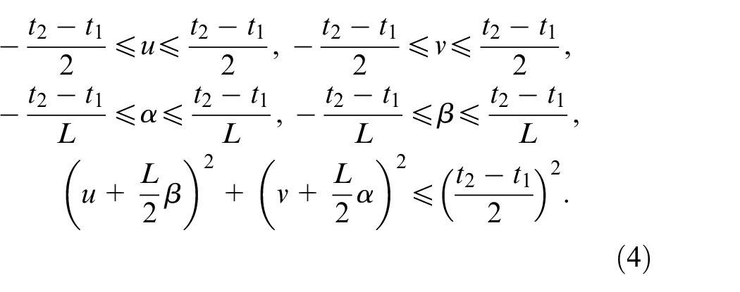
Assume that there are
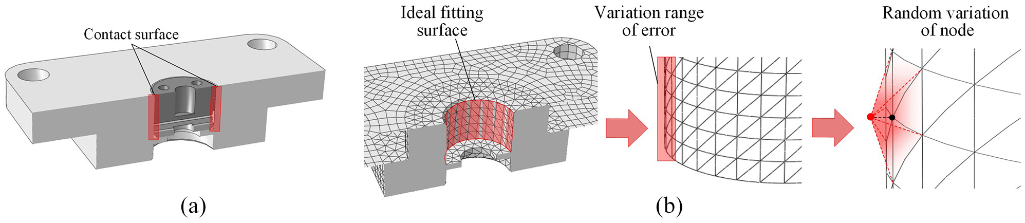
The modeling of form error in the interference fit: (a) shaft-hole structure in the jet-disk assembly, (b) random variation of contact surface.
The interference fit process with press force on the end face of shaft-hole structure is simulated numerically and the data of coordinates of fitting surfaces are measured. The relative profile point collection is obtained and the functions of axes of fitting cylinders are given by
where
where the error propagation coefficients are decided by the deviation position of cylinder before the interference fit. The coefficients could be integrated into a diagonal coefficient matrix

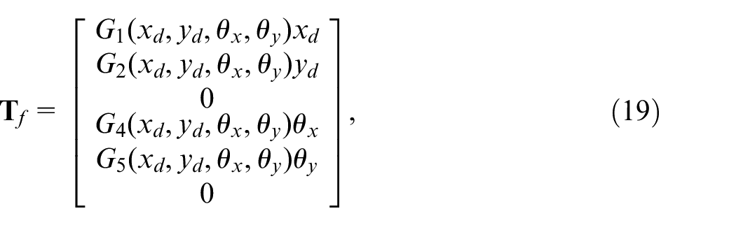
The theory of error propagation for interference fit with form error has been elaborated. The form error of actual cylinders is fitted to the torsor model, and the error propagation coefficient is introduced to integrate the flexible deformation of interference fit stage into the rigid assembly error propagation. Figure 7 shows the flow-chart of error analysis using the proposed error model. The computational model makes it possible to conduct the assembly error analysis by statistic method. In the next session, a jet-disk assembly with interference fit structure is presented to introduce the procedure of analysis and verify the computational model.
Analysis procedure of the assembly with interference fit stage.
Case study
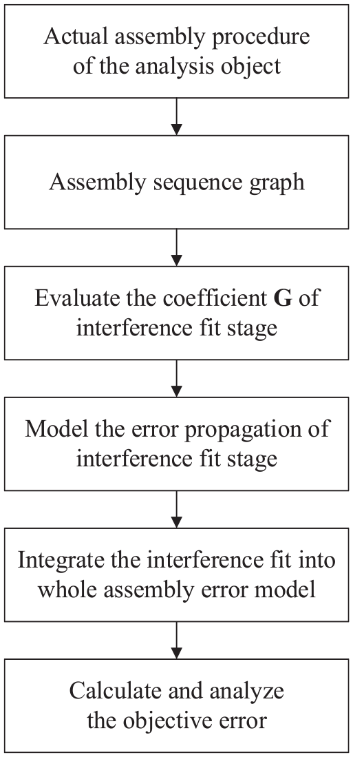
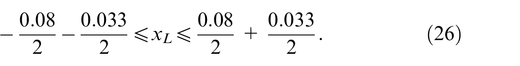
The jet-disk assembly is shown in Figure 1 with the shaft-hole fit characteristic. The error analysis of the clearance variation is necessary for quality control of the high precision servo valve. The jet-disk assembly comprises the base part, the upper end cover part and the lower end cover part. Different manufacturing errors of these parts are propagated to the displacement and rotation of the clearance between two faces of end covers. The cylindrical hole structure of the base is restricted by a position tolerance with the profile of the base and the value is 0.08. The cylindrical hole surface has a cylindricity tolerance valued at 0.06. The cylindrical axis of upper end cover is restricted by a perpendicularity tolerance valued at 0.04 with the bottom face and has no form error in the cylindrical surface. The top face of lower end cover is restricted by a parallelism valued at 0.02 with the bottom face.
The connection method is illustrated in Figure 8. The connection between the base and lower end cover is established by adhesion agent. The connection between the base and upper end cover is established with interference fit by press force conducted on the end face. The target feature is the position error of clearance between two faces of end covers. The errors of target feature are accumulated by every tolerance feature in the assembly, which contains the propagation of form error component through the interference fit stage. The error computational model for the jet-disk assembly is established as follows.
Step 1. Build the assembly sequence graph. The assembly relationship of the parts is divided into the internal pair and the contact pair. Figure 9 shows the relationship between error features of the base part, upper end cover and lower end cover. Here the root feature is the profile of base part. Five pairs are contained in the assembly process, comprising three internal pairs and two contact pairs. The internal pair IFE1 is from the profile surface(0) to the cylindrical hole surface(1) of base part. The internal pair IFE2 is from the cylindrical side surface(2) to the bottom face(3) of upper end cover, and the internal pair IFE3 is from the bottom face(4) to the top face(5) of lower end cover. The contact pair CFE1 is a special flexible pair with deformation which represents the interference fit between the cylindrical hole surface(1) and the cylindrical side surface(2). The contact pair CFE2 is a planar connection between the hole surface(1) and the bottom face(4). The error analysis object FR is the variation between the top face(5) of lower end cover and the bottom surface(0) of upper end cover, which represents the clearance variation between end covers. So the closed-loops of error propagation chains are built as IFE1-CFE1-IFE2-FR and IFE1-CFE2-IFE3-FR.
Step 2. Establish the error propagation model of interference fit stage. The error propagation coefficient of interference fit in the jet-disk assembly is obtained by simulating the form error and assembly process numerically. The profile point data is collected and the coefficient

Connection method of jet-disk assembly.
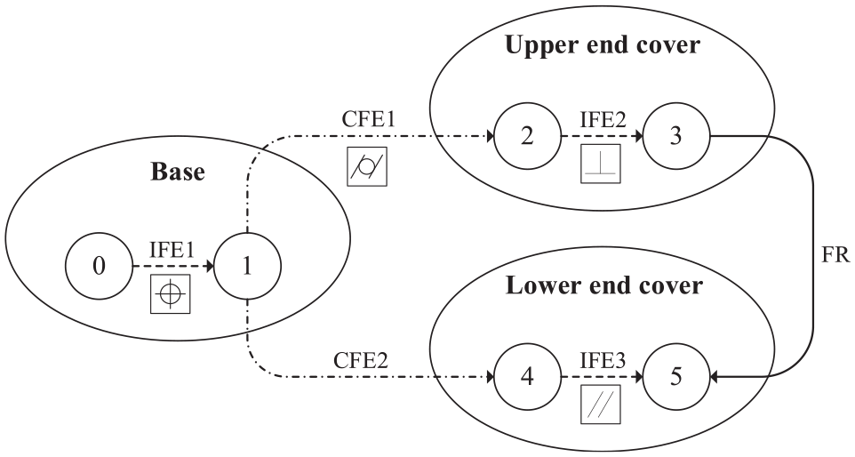
Assembly sequence graph of features.
where
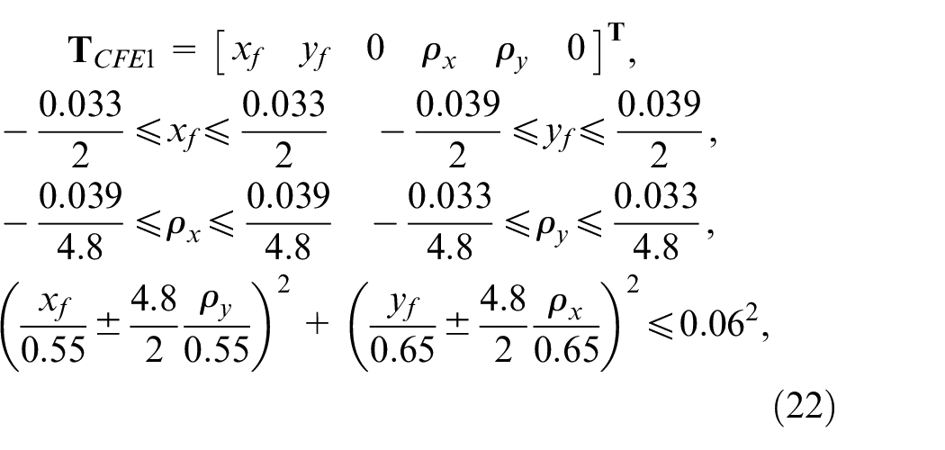
where
Step 3. Establish the error model of the whole assembly. The error propagation of the interference fit stage is integrated into the complete error model of jet-disk assembly. Two error propagation paths are recognized in Figure 9 and each propagation path has three pairs. The relative Jacobian matrixes and the error torsors are derived and taken into equation (17) as
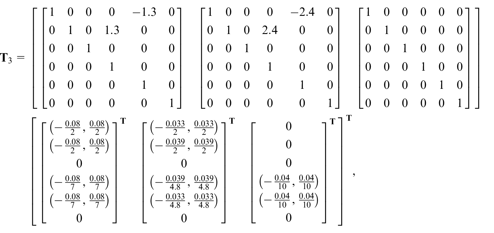
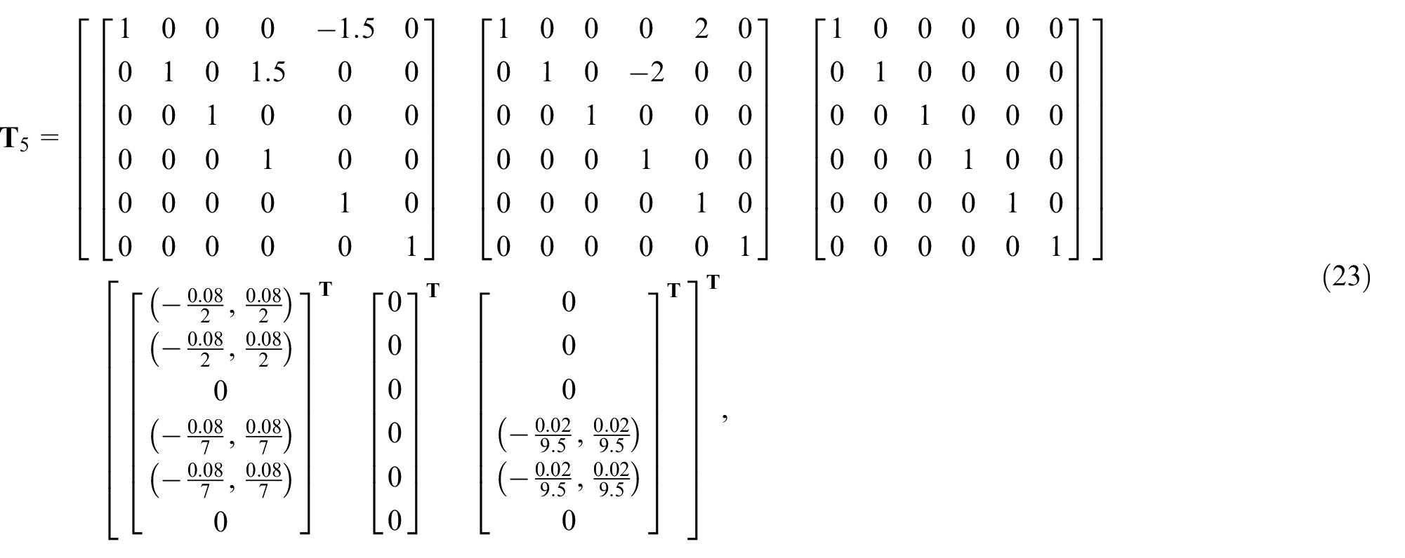
where

Step 4. Calculate the target error. The flexible error of interference fit stage is integrated into the torsor model to calculate the error accumulation with other rigid errors, so the statistical method could be used in the analysis of target variations. A certain degree of defective rate is allowed in the statistical analysis method which provides a better estimation of the actual production. The Monte Carlo method is conducted to generate random torsor samples which are satisfied with the variation ranges and constraint functions. When the manufacturing errors of features satisfy normal distributions, the simulation samples are generated by the distribution parameter
where
Comparison and discussion
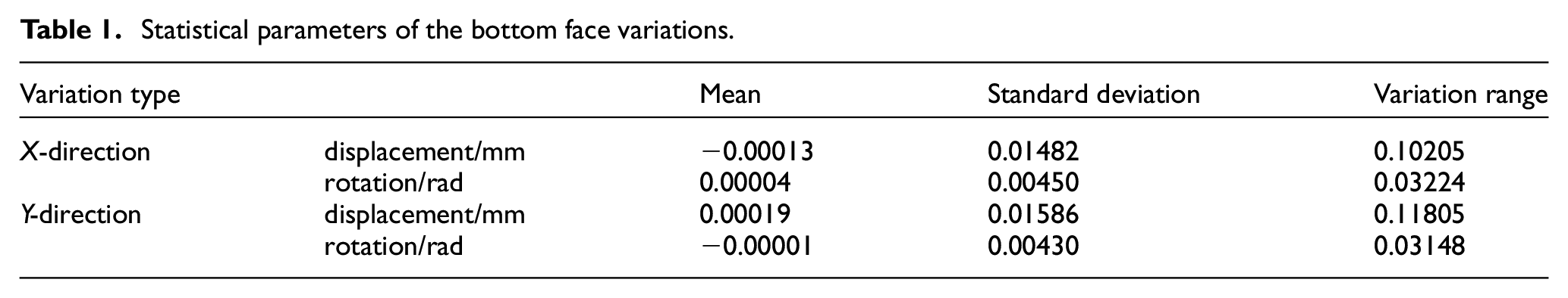
The error computational model for interference fit is used to analyze the jet-disk assembly. Figure 10 shows statistical histograms of the bottom face variations of upper end cover. The displacement and rotation errors are affected by the interference fit stage in the assembly chain. According to the displacement error distributions of the bottom face in the X direction and the Y direction, 75% of displacement errors are less than 0.02 mm. For the rotation error of the bottom face in two directions, 85% of rotation errors are less than 0.007 rad. The statistical parameters of the bottom face variations are given in Table 1. The displacement error in the X direction is smaller than the error in the Y direction and the rotation error in the X direction is larger than the error in the Y direction. The interference fit error propagation coefficients differ in the two directions for the shaft-hole structure. The error propagation coefficient is larger in the Y direction than that in the X direction. The displacement error in the Y direction and the rotation error in the X direction are generated by the cylindrical deformation in the Y direction. Therefore, the weakening effect of error propagation in the interference fit process is smaller in the Y direction and the effect causes larger bottom face errors at the end of the error propagation chain.
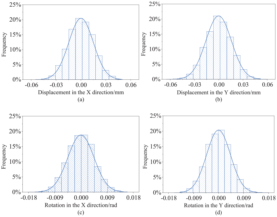
The bottom face variations of upper end cover:(a) and (b) displacement and rotation errors in the X-direction, (c) and (d) displacement and rotation errors in the Y-direction.
Statistical parameters of the bottom face variations.
The results of error computation are compared with the traditional error analysis models for evaluating availability and accuracy of the proposed model. The maximal variations of bottom face calculated by different error computational model are shown in Figure 11(a). Four methods are used to analyze the displacement and rotation errors of bottom face along the X direction. The finite element method is conducted by solid model of jet-disk assembly in the software ABAQUS. The manufacturing error is considered by modifying meshes as illustrated in Figure 6(b) and every manufacturing error in Figure 9 is included. The finite element model combines the actual material properties, deviations of features and assembly deformations comprehensively. High precision could be reached by the three-dimension solid element for quasi-static analysis of interference fit. The numerical results are showed in Figure 11(b) which could be set as the standard. Then the accuracy of other models is evaluated. The linear chain model is established by IFE1 and CFE1 along the X direction, in which only the components of displacement are calculated as
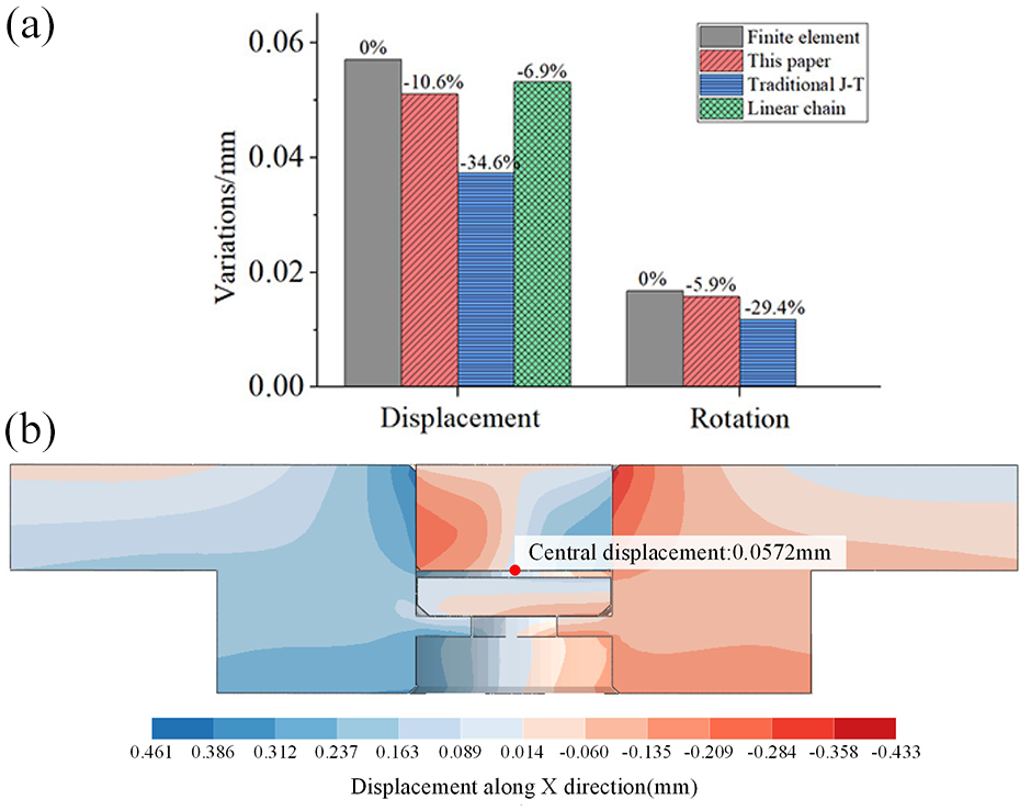
Comparison of feature variations in different error models: (a) the accuracy of different models with finite element method considered standard and (b) the results of finite element method.
The traditional Jacobian-Torsor model utilizes the displacement and rotation components of IFE1 and IFE2, but the tight coupling of interference fit CFE1 is neglected according to the error variation rule. 21 The proposed error computational model has a more accurate prediction in both displacement and rotation errors than the traditional Jacobian-Torsor model. The linear chain model has a high accuracy in the calculation of displacement error, but rotation error cannot be considered in this model.
The clearance variation between the upper and lower end cover could be represented as the concentricity and deflection which are illustrated in Figure 12(a). In the assembly chain, the top face error of lower end cover and the bottom face error of upper end cover are calculated separately and the clearance variations are derived. Figure 12(b) and (c) shows the distributions of concentricity and deflection of the cylindrical clearance with marking the acceptable range for the qualified production. Different error models are used to calculate the clearance variations. For the concentricity of clearance shown in Figure 12(b), the largest result is given by the linear chain error model in which the extreme surface position is calculated. The error computational model derives larger results than the traditional Jacobian-Torsor error model because the cylindricity error of interference fit stage is considered in the proposed model which increases the end face displacement through error propagation. For the deflection variations in Figure 12(c), the deflection errors calculated by the interference error model are larger than the results calculated by the traditional Jacobian-Torsor model. The rotation error cannot be considered in the linear chain model. Error analysis of products conducted by the linear chain error model is excessive and the result increases the unnecessary cost. The proposed computational model derives wider acceptable range without ignoring the error of interference fit stage. The error computational model of cylindrical form error in the interference fit stage could characterize the deformation of shaft-hole structures better. The prediction of clearance variations of the jet-disk assembly could be conducted with higher accuracy.
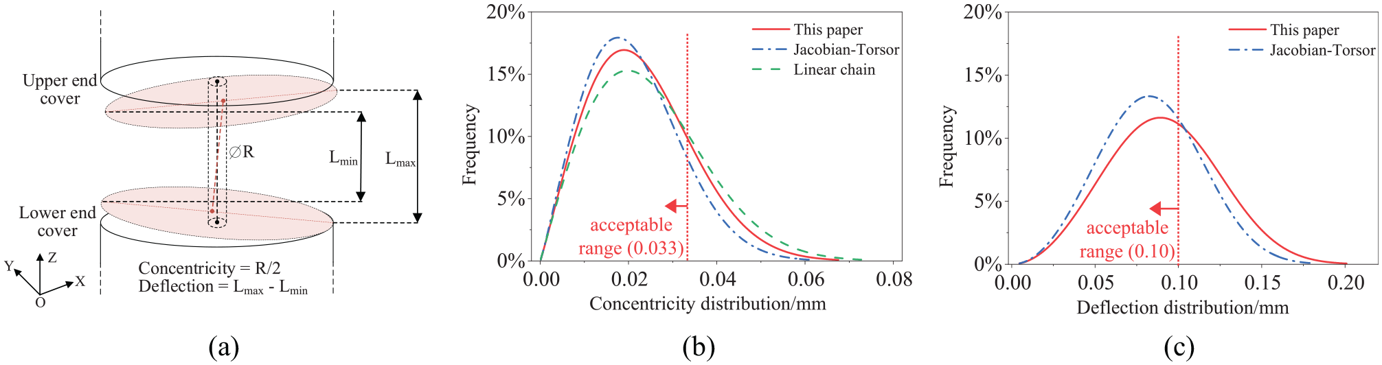
Variations of clearance: (a) definition of concentricity and deflection between end covers, (b) concentricity calculated by different error models, and (c) deflection calculated by different error models.
Conclusion
In this paper, an error computational model for the cylindrical form error in the interference fit is proposed. The cylindrical form feature is quantified and integrated into the small displacement torsor model. The error propagation coefficient of interference fit is introduced to represent the flexible deformation of the shaft-hole fitting cylinders in the assembly process. The evaluation method for the error propagation coefficient is given by numerical simulation. A jet-disk assembly is adopted as the study case, and the analysis process of target error is introduced using the error computational model. The results show that the error computational model could embody the weakening effect of form error propagation in the interference fit stage. Higher accuracy and wider availability are achieved in the proposed error computational model, which could be used to direct the design and production of high precision products with the interference fit stage.
Footnotes
Appendix
Declaration of conflicting interests
The author(s) declared no potential conflicts of interest with respect to the research, authorship, and/or publication of this article.
Funding
The author(s) disclosed receipt of the following financial support for the research, authorship, and/or publication of this article: This work presented received the financial support from the National Key Research and Development Program of China (2019YFA0709001) and the National Natural Science Foundation of China (No. 51775345).