
Abstract
The composite rupture discs are a safety device that burst at the specified pressure and prevent overpressure and damage to equipment by releasing the fluid at high flow rates. The burst pressure is determined by the bulge formed and then slotted sheet metal. In the hydraulic bulge-forming stage, the sheet is subject to biaxial stress, and after slotting, it is subject to uniaxial tensile stress. Due to the change in the loading type, the sheet has a nonlinear strain path during the bulge-forming and burst test after slotting. In the nonlinear strain paths, the equivalent failure strain changes according to the strain path. In this paper, based on the FEM simulation results and experimental tests, the relationship between plastic failure strain in uniaxial tensile state and the maximum pre-strain due to bulge forming is investigated. According to the results of this paper, when the sheet sufficiently forms under hydraulic pressure, the maximum strain in hydraulic bulge-forming and the equivalent failure strain after slotting are equal. Based on this result, analytical relations were developed to predict the burst pressure of composite rupture discs. This relation estimates the burst pressure of composite rupture discs with an average error of about 13%.
Introduction
Analytical relations for predicting the sheet metal forming behavior reduces production time and costs. A rupture disc is a safety device designed to burst at the specified pressure to protect vessels, piping, personnel, and equipment from unexpected excessive fluid pressure. Commonly rupture discs are used in the petrochemical, pharmaceutical, and food-process industries, nowadays rupture discs have a wide range of applications from nuclear, aerospace, defense, automotive, railroad, HVAC, power, and energy systems to research laboratories and beyond.
1
For manufacturing rupture disc, a “trial-and-error” manufacturing process is employed to establish the final design. During the manufacturing rupture disc, skilled technicians adjust design variables such as construction material, material thickness, crown height (bulge-forming height), score depth (in scored type discs), and material thermal treatment.
2
In manufacturing the composite rupture disc, the sheet metal blank subjects to biaxial stress during bulge-forming; then, the slots are created on the bulge-formed disc by laser. The slotted disc determines the burst pressure of the composite rupture disc. During the burst pressure test of the composite rupture disc, the disc is under uniaxial tension; because the slotting pattern causes the stress changes from biaxial during bulge forming to uniaxial during burst test after slotting. A non-slotted sealing membrane, such as fluoropolymers, is used under the slotted disc to prevent fluid leakage from slots. Therefore, this type of rupture disc has at least two layers and is named composite rupture disc. The metallic top layer is for burst pressure control, and the non-metallic membrane is for sealing. The effect of sealing membrane on the burst pressure is ignorable. The slots cause the rupture discs to open in a predetermined pattern and therefore have a non-fragmentation design. According to experimental tests on non-slotted rupture discs, Lake and England
3
concluded that if the burst pressure called
In sheet metal forming, the failure strain varies at different load types. For example, a sheet under biaxial stress has more failure strain than uniaxial tension. 13 According to previous studies, changing the strain path causes the failure strain changes. The forming limit curve (FLC) is a conventional tool for formability prediction in sheet metal forming processes. The FLC is a strain-based failure criterion in which the principal in-plane strains at failure evaluates. Most sheet metal forming processes are multistage, and the major true strain to the minor true strain ratio (ε1/ε2) changes during the forming process. For example, after forming the sheet under biaxial tension, if it deforms under uniaxial tension, a nonlinear strain path occurs. The limitation of the FLC is that if the nonlinear strain path occurs, it cannot estimate the forming limit.14,15 The Forming Limit Stress Diagram (FLSD) is formability based on the state of principal stress rather than the state of strain. The FLSD is obtained by plotting the calculated principal stresses at necking. Panich et al. 16 concluded that the stress-based forming limit curves could more precisely describe the formability behavior of high-strength steel sheets than the strain-based forming limit curves. Wu et al. 17 confirmed that at least in comparison to the FLD, the FLSD is not sensitive to strain path changes. More specifically, the FLSD is almost path-independent when the pre-straining is not very large. They concluded that in the case where pre-straining is so large that it almost reaches the forming limit strain, the limit stresses are noticeably different from the FLSD calculated assuming linear deformation paths. Stoughton and Yoon 18 proposed a new strain-based forming limit criterion based on a polar diagram of the effective plastic strain with the direction defined by the arctangent of the ratio of the current plastic strain rates. Polar Effective Plastic Strain diagram (PEPS) considers pre-deformations and considers an effective failure strain for each nonlinear strain path that includes multi-stage forming. Jocham et al. 19 used the cruciform specimens sheet to create nonlinear strain paths and study its effects. In their experimental tests, the modified toolset consists of the common Nakajima punch, a modified blank holder, and a cruciform specimen. The blank holder consisted of four adjustable draw beads. Hongzhou et al. 20 used two-stage sheet forming to create a nonlinear strain path. The first straining stage was obtained by drawing the constrained sample as the punch moved down. The second stage was performed by reverse-drawing the blank with the semi-ellipsoidal dome. For creating different strain paths, Zhubin et al. 21 proposed a novel test method. That named bulging with stepped-dies for continuous nonlinear biaxial tensile deformation of sheet metals. In that study, the section shape of a stepped-die cavity varies as the depth increases. They established a theoretical model to calculate the stress components at the pole. Bonatti and Mohr 22 studied the efficiency of the neural network model to predict forming limits for Bi-linear strain paths.
In this paper, for predicting the burst pressure of the composite rupture disc, an analytical relation is presented. In the analytical equations, the effective parameters such as strain due to bulge forming or nonlinear strain path, sheet thickness (t0), bulge-forming diameter (d) and height (h), hardening coefficient (K), and hardening exponent (n) of the sheet, and slots pattern considered. The experimental tests and FEM simulations are used to find the relation between the failure strain in the composite rupture disc burst test and the bulge forming strain. Also, based on the analytical equations, the effect of the parameters is investigated.
The experimental tests
The production steps of the composite rupture disc include blanking or cutting the sheet into the disc, forming the disc to a dome shape by hydraulic bulge forming, and then slotting the dome-shaped disc by laser. After these steps, the sealing membrane is used under the slotted disc to prevent corrosion and leakage from slots. The disc material in experimental tests is AISI 316L with a thickness of 0.3 mm. The discs bulge formed at different heights using various hydraulic pressure to investigate the effect of sheet metal forming in bulge forming on the burst pressure or failure strain after slotting. After bulge forming by different hydraulic pressure, the slots with a similar pattern created by laser on the bulge-formed discs. The difference between these specimens is the amount of plastic strain caused by biaxial stress in the bulge forming. A transparent thin PVC film with a thickness of 0.15 mm was placed under the slotted layer to prevent leakage from the slots. This layer is very deformable, and its effect on the burst pressure is Negligible. To determine the burst pressure of prepared specimens, air pressure increased until they burst. The burst test procedure is according to ISO 4126-2. During the burst pressure test, the pressure transmitter with 0–60 bar pressure range, LabVIEW software, and the pressure gauge were used. The bulge forming and the burst test setup are shown in Figure 1. During bulge forming for measuring the apex height (h), a digital depth-caliper was used. For measuring the hydraulic pressure, a pressure transmitter and digital indicator were used. For creating the height-pressure chart, a camera simultaneously was recorded the data from the pressure indicator and depth-caliper.
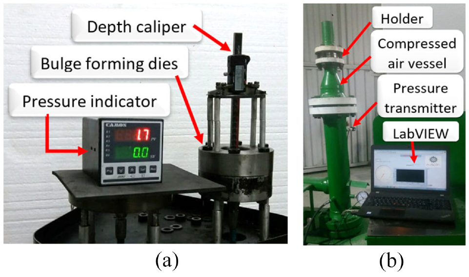
(a) Bulge forming setup and (b) rupture disc burst test setup.
The tensile test was performed according to the ASTM-A370 to evaluate the mechanical properties. According to the test result, the yield strength is 226 MPa, the ultimate tensile strength is 625 MPa, and the elongation (in 2in gauge length) is 67.5%. The tensile test results were used in the FEM simulation.
The images of the prepared specimens at different heights (h) and bulge forming diameter d = 52 mm with a similar slotting pattern are shown in Figure 2. Also, the images of prepared specimens with different bulge-forming diameters (d) and slot patterns are shown in Figure 2. The slot pattern created by the laser is shown in Figure 3.
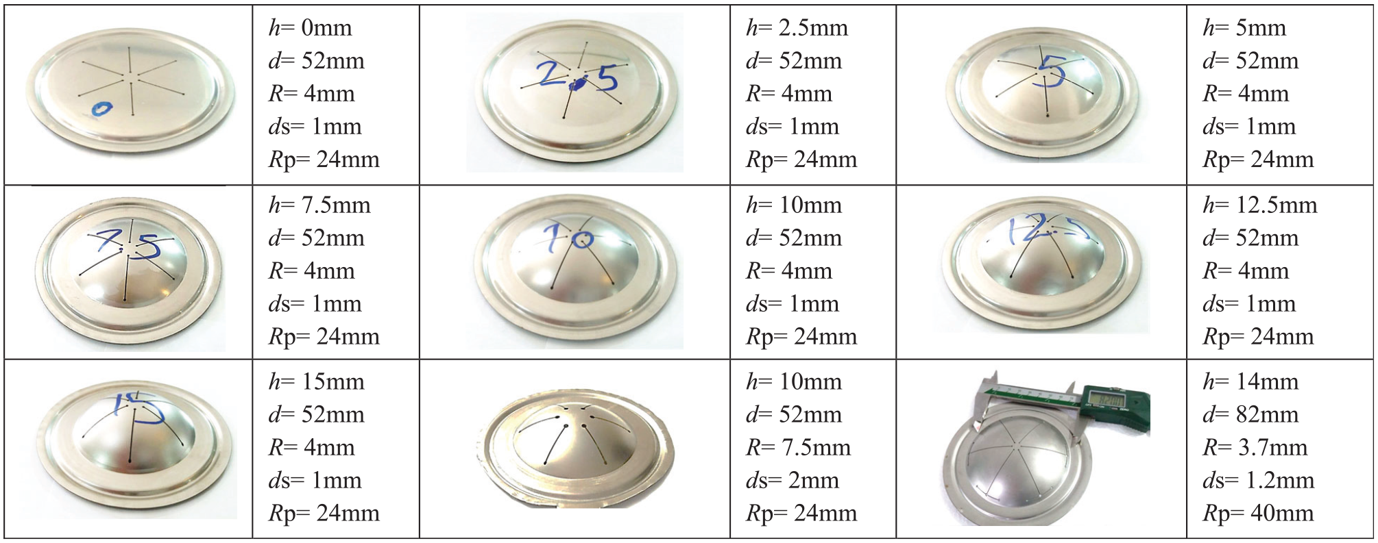
The specimens bulge-formed in different apex heights (h), and the specimens with different slot patterns and bulge forming diameter.
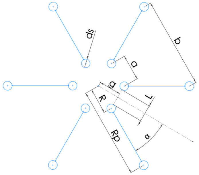
The slot pattern on the bulge-formed sheet metal.
Finite element simulation
In the FEM simulation of the composite rupture disc, the plastic deformation in bulge forming should be considered in the burst test simulation of the slotted disc. Therefore, the simulation was performed in three steps: bulge forming, slotting, and burst test. The simulation of the bulge forming step was performed by Abaqus-implicit, and to simulate the failure after slotting, Abaqus-explicit was used. The element type in simulation by Abaqus is C3D8R. The slotting simulation was done by deactivating slot pattern elements after bulge forming. Sheet properties were obtained from the tensile test. Only a limited strain range can be determined in the tensile test. To extend the true stress–true strain curve to cover higher true strains in actual forming operations, several empirical functions such as Hollomon’s equation are available and used to extrapolate the measured and calculated data.
23
In general, using any strain hardening relations such as swift, Johnson Cook, and Ludwik for extrapolating the tensile test results and applying it to the material properties in the FEM simulation is possible. Hollomon’s equation was used for extrapolating the tensile test stress-strain curve because the AISI 316L strain-hardening data points, fit with Hollomon’s equation. According to the tensile test, the Holloman equation for AISI 316L is
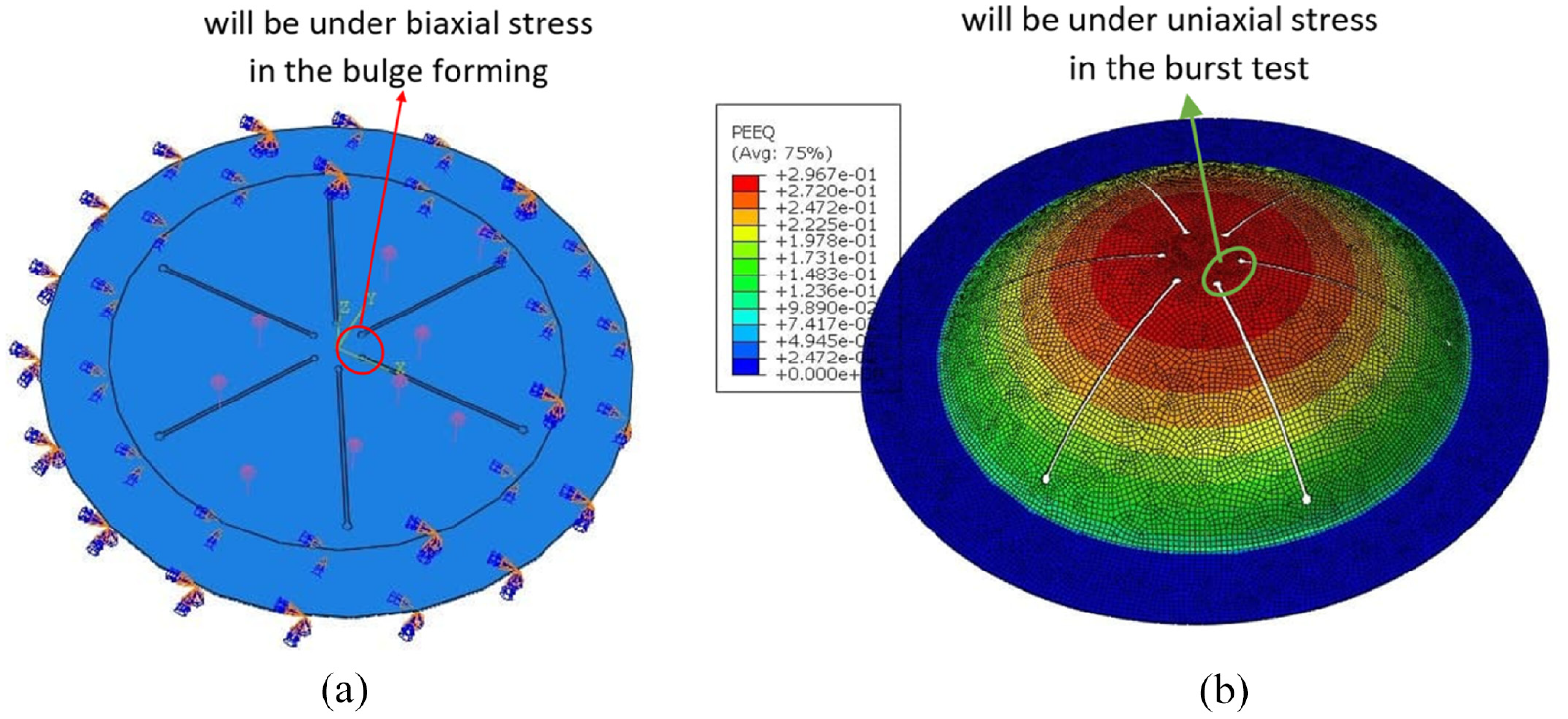
(a) The initial model for bulge-forming and (b) the initial model for burst test simulation.
Due to the use of the stop bead and tightening the bolts in high torque by torque meter (130 N.M), the sheet is not drawn like a deep drawing process. Therefore, as shown in Figure 4(a), the fixed boundary condition is used in the FEM simulation. As shown in Figure 4(b), the uneven plastic strain distribution is considered at the initial model in the burst test simulation.
In experimental tests to investigate the effect of bulge forming height (h) on the burst pressure, the specimens were bulge-formed at different apex heights (h). In the FEM simulation, the initial models were formed at different apex heights (h) like the specimens in the experimental test to investigate the effect of bulge-forming strain on the failure strain at the burst pressure. The slotting pattern created after bulge forming in the experimental tests and FEM simulations are similar. Before slotting, in the bulge-forming simulation, the pressure is increased linearly at any time until the model reaches the desired apex height (h). To obtain the necessary pressure to form each disc in the simulation to reach the desired apex height (h), the pressure-apex height chart was plotted according to experimental and simulation results. The pressure-apex height curves for the discs with bulge forming diameter d = 52 mm and d = 82 mm are shown in Figure 5.
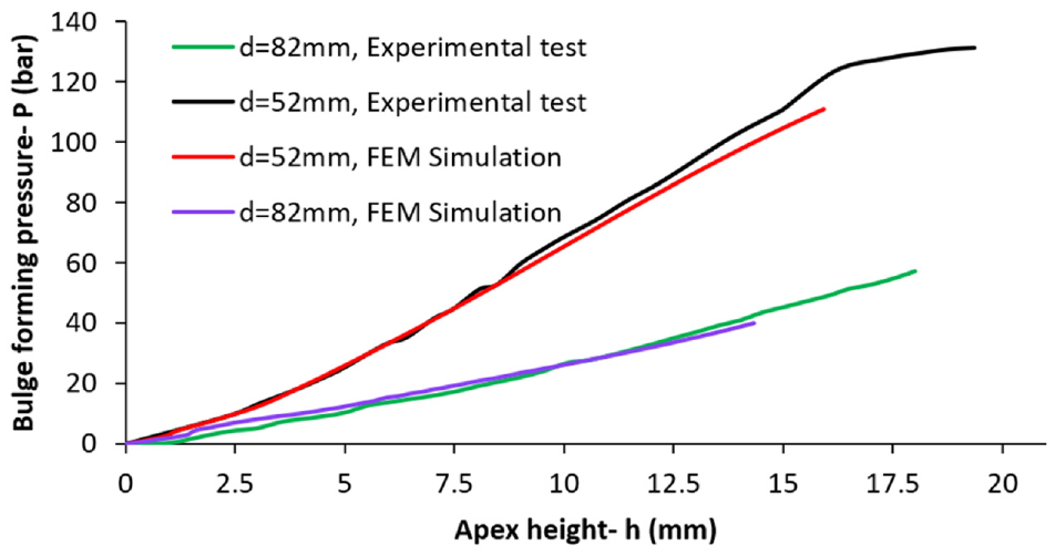
Pressure-height curves of bulge-forming based on experimental and simulation results.
According to FEM simulation results, the plastic strain distribution is not similar in the discs formed at different apex heights (h). At any bulge height (h), the maximum plastic strain occurs in the apex. Also, right before burst pressure, according to FEM simulations, the plastic strain distribution in each specimen with different bulge height from the center of the disc to the peripheral of the dome is shown in Figure 6. While the strain distribution before the burst test is as Figure 7.
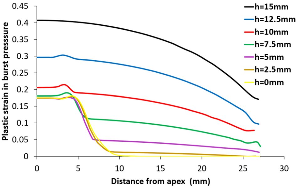
Plastic strain distribution at burst pressure in the specimen with different apex heights (t = 0.3 mm, d = 52 mm, dc = 8 mm, s = 1 mm).
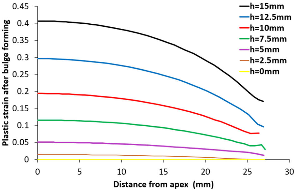
Plastic strain distribution at the initial of the burst test in bulge-formed discs with different apex heights. (t = 0.3 mm, d = 52 mm, dc = 8mm, s = 1 mm).
The approximate failure strain is obtained using FEM simulations. For this purpose, the strain from the simulation model is measured at the pressure that the composite rupture disc burst in the experimental test. Figure 6 shows the strain distribution at the burst pressure. The rupturing occurs at a distance of 4 mm from the center of the disc. The strain in this location is considered the failure strain. According to Figures 6 and 7, the specimens with no or little plastic deformation caused by the bulge-forming have more plastic deformation during the burst test, and their failure plastic strain is not more than 0.2. As the forming height (h) before slotting increases, less permanent deformation occurs during the burst pressure test after slotting. According to Figures 6 and 7, in bulge-formed discs with bulge forming diameter d = 52 mm and the apex heights higher than h = 10 mm, the failure strain at the burst pressure is equal to the strain caused by bulge-forming. The plastic strains occur in bulge forming and after slotting, are caused by different types of stress. When the bulge forming height to diameter ratio (h/d) is higher than 20%, after slotting when the disc is subject to pressure until it reaches burst pressure, approximately there is not plastic strain that causes a nonlinear strain path. In this study, the rupture pressure after the first stage of bulge forming has been investigated. So, in the second stage of forming, which is apply of pressure to reach the rupture point, the strain path is linear. Therefore, in this step, we can use the linear equations governing the problem, which are described in the next section.
Analytical relations
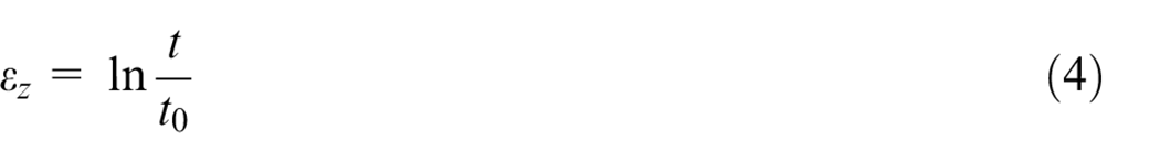
The metallic disc that the slots are created on its dome by laser after bulge forming determines the burst pressure of the composite rupture disc. The bulge forming is the first step of manufacturing composite rupture disc from the sheet metal blank. The pre-bulged disc is very stable and resists flexing and further bulging from the increasing system pressure, permitting static system pressures up to 80% of the marked burst pressure. 2 Based on experimental results and FEM simulations, the bulge forming increases the failure strain and the burst pressure of the composite rupture disc. The hydraulic bulge forming and hydraulic bulge test are similar. In the bulge test, the sheet is under biaxial tensile stress. This test is used to investigate the mechanical properties of the sheet under biaxial tension. In the bulge test, the maximum achievable strain before necking is much larger than in the tensile test. 13 In the bulge test, the periphery of the metal sheet is restrained by a draw bead, which prevents its radial displacement. 24 The schematic of the hydraulic bulge forming, composite rupture disc burst test, and the specimen after bulge forming and burst test are shown in Figure 8.
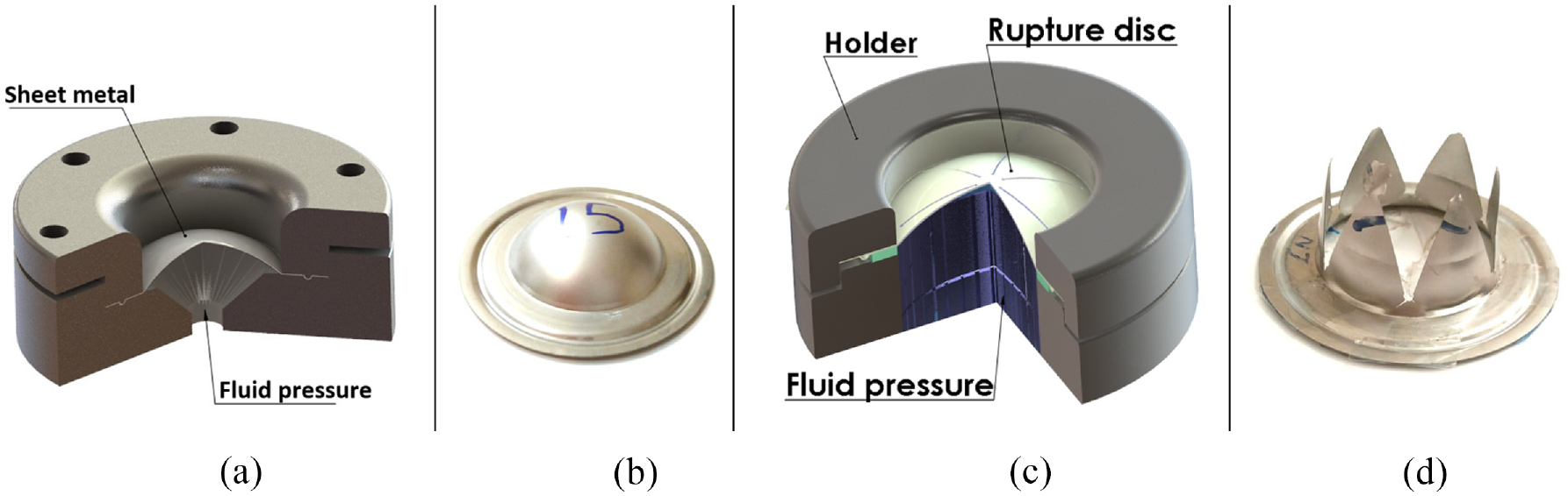
(a) Schematic of hydraulic bulge forming (b) The specimen after bulge forming (c) Section view of composite rupture disc in burst pressure test, and (d) The disc after burst test.
In a monotonic, proportional process the effective, or equivalent strain
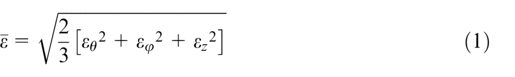
The

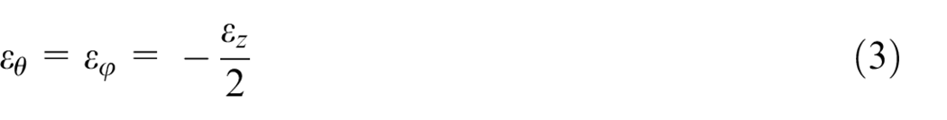

Therefore, during bulge forming, the equivalent strain in the center of the disc is equal to the strain in the sheet thickness direction. The thickness reduction is not the same across the sheet, and the apex of the disc has the maximum thickness reduction and plastic strain. Figure 9 shows the dimensional parameters of the bulge forming.
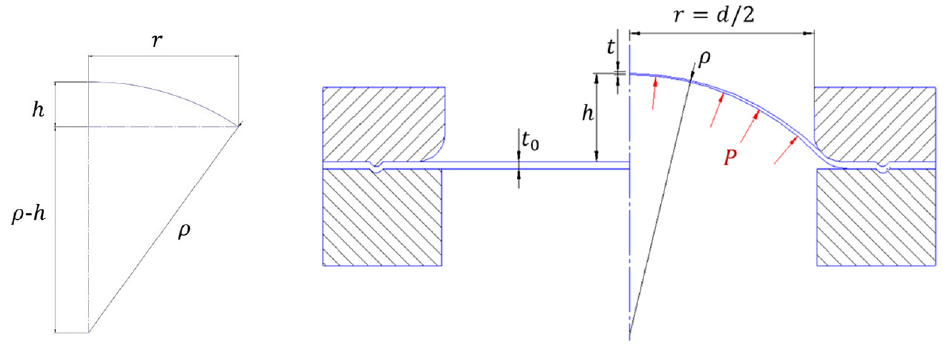
dimensional parameters of the bulge forming.
Koc et al. 26 examined the relationships presented to estimate the thickness reduction in the central region or apex in the bulge test. They concluded that equation (6) is more accurate than others. Marandi et al. 27 used this equation to investigate the relationship between height and pressure in two-layer hydraulic bulge forming.
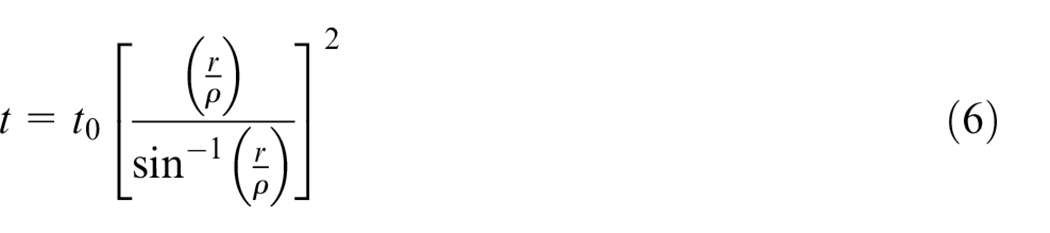
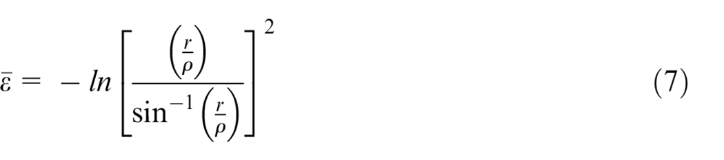
Therefore, according to equations (4)–(6), the amount of strain created at each height (h) before slotting, is equal to:
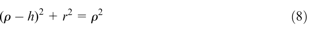
Based on the geometric relations of Figure 9:
Therefore 28 :
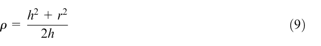
Therefore, according to equations (6)–(9), as the bulge height (h) increase, the equivalent strain increase, and the thickness of the apex (t) decrease. The ratio of
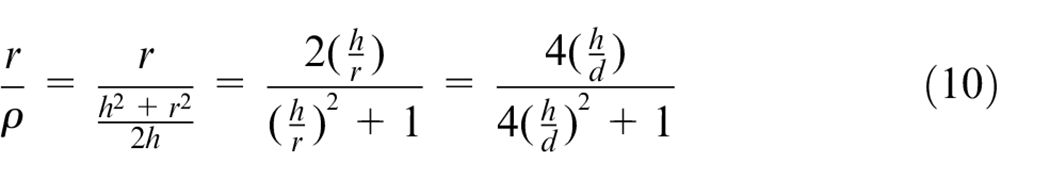
Based on equations (7) and (10), the strain created in the center of the sheet in each height to diameter ratio is equal to:
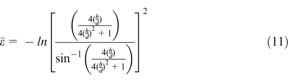
According to equation (11) in specimens, when bulge forming height to bulge-forming diameter ratios (h/d) are equal, the amount of created strain is equal.
In the following, analytical equations are presented for slotted disc after bulge forming. The slot pattern divides the disc into six or other numbers of petals. Figure 10 shows the free body diagram of each petal of the composite rupture disc. In the burst test, the forces resulting from the fluid pressure and the reaction forces created in the sheet are in equilibrium.
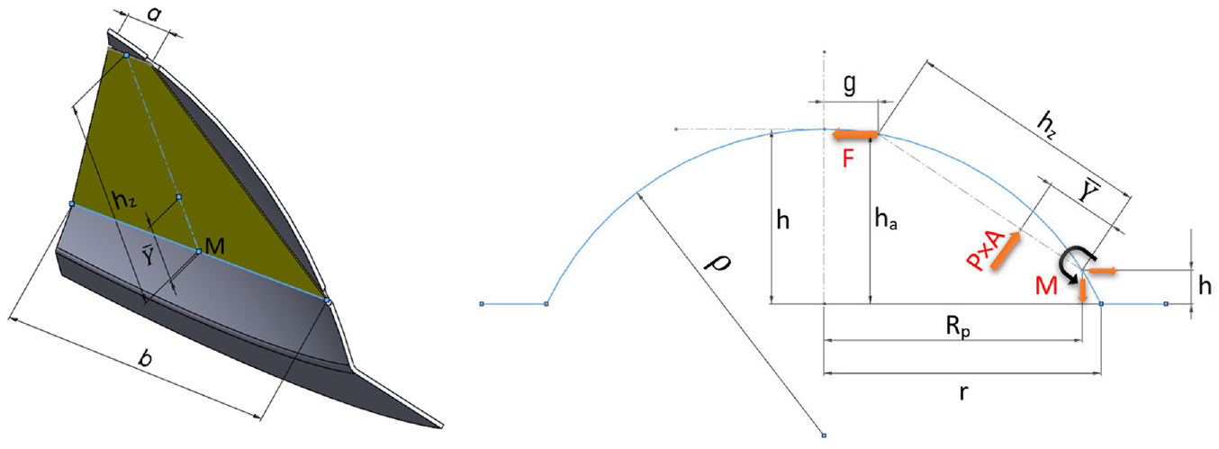
Free body diagram of each petal of the composite rupture disc.
Each petal has a trapezoidal shape. For writing the equilibrium equation of moments, the equivalent force from the fluid pressure can be considered on the center of the trapezoidal shape (
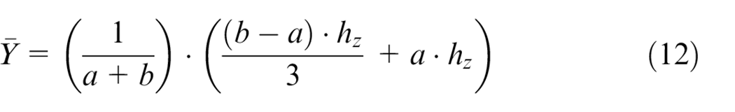
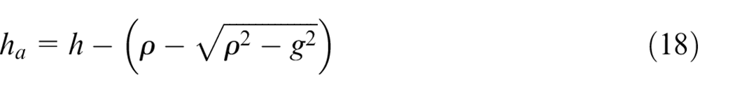
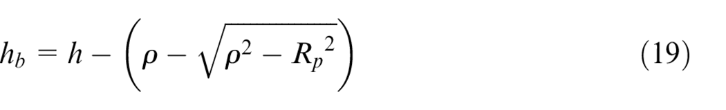
The lengths of


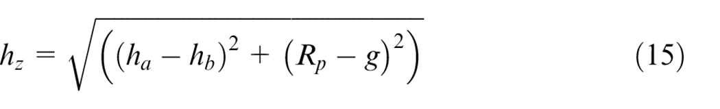
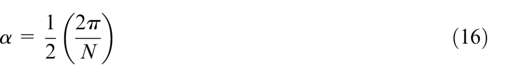
The N is the number of petals that are divided by slotting. The

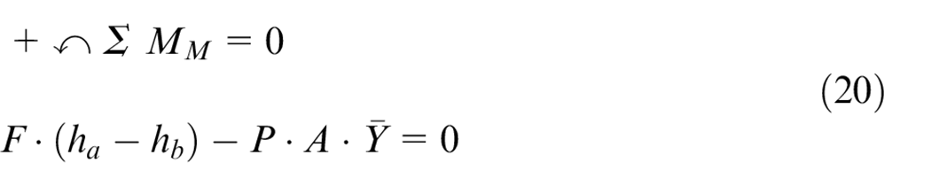
For obtaining the burst pressure of the composite rupture disc, the moment equilibrium equation about M needs to be written for the petal. The moment required to bend the sheet is negligible. The equation of moment equilibrium about the M axis due to the fluid pressure P and the reaction force F in the sheet is as follows:
A is the area of the trapezoid which the fluid pressure is applied:
Based on experimental tests, the bulge-forming increases the burst pressure and prevents the rupture disc has plastic deformation in operating pressure. Bulge-forming causes the disc to have a higher allowable working pressure to burst pressure ratio. According to equation (11), when the height to diameter ratio (h/d) in bulge forming is the same, the amount of strain due to the bulge forming is equal. According to the FEM simulation result, if the height to diameter ratio (h/d) in bulge forming is more than 20%, the strain due to the bulge forming is approximately equal to the failure strain in the burst test of the rupture disc. In other words, if the sheet has enough plastic deformation under the biaxial stress in the bulge-forming (h/d > 20%), it will not have more plastic strain after slotting in the state that it is under uniaxial tensile stress. The maximum stress

The t is the thickness of the sheet after bulge forming and obtained from equation (6). According to Figure 3, the L is the length of the zone that connects each petal to the center of the disc. This zone is under the reaction force F. The maximum force Fmax. that the sheet of the rupture disc can withstand in the burst test is equal to:

The L is equal to:

By substituting derived equations to equation (20), the burst pressure of composite rupture disc is obtained by the following equation:
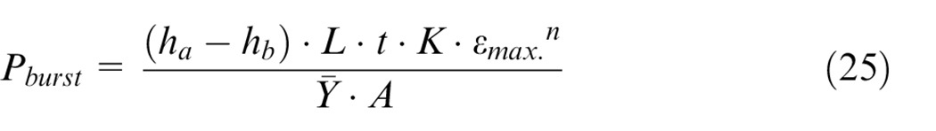
Equation (25) can be used for all sheet metals used for manufacturing composite Rupture discs such as Hastelloy C-276, Inconel 600, and Monel 400.
Results and discussion
For predicting the burst pressure of the composite Rupture discs by an analytical equation, the FEM simulation was used, and the results were compared with experimental tests. The simulations were performed to find the relation between failure strain and bulge-forming strain. According to the simulation results, if the ratio of bulge-forming height to diameter (h/d) is more than 20%, the failure strain in the burst test is approximately equal to the created strain in the bulge forming. According to this result, analytical equations were obtained to predict the burst pressure of the composite rupture disc and compared with the experimental results. The bulge-forming before slotting prevents plastic deformation at operating pressure and increases the maximum allowable operating pressure to the burst pressure ratio. The extracted analytical relation can predict the burst pressure when the bulge forming height to diameter ratio (h/d) is higher than 20%, and therefore no plastic deformation occurs after slotting. Figure 11 shows the effect of apex height (h) on the burst pressure.
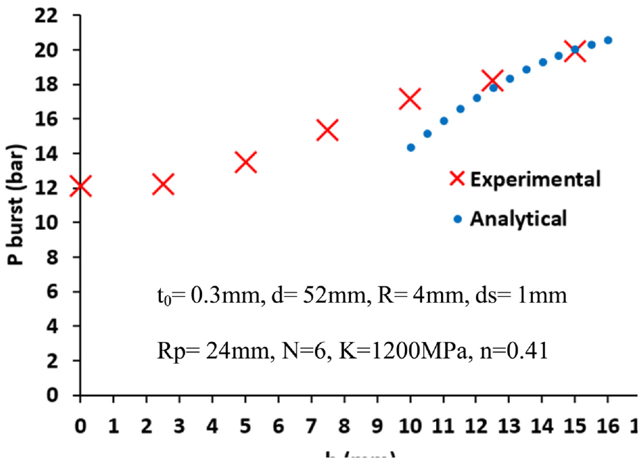
The effect of apex height (h) on the burst pressure after slotting.
More difference between estimated burst pressure by analytical equation and the experimental test in the less bulge-formed specimens is related to the plastic deformation in the burst test, which is ignored in the analytical equations. In the case of low apex height in bulge-forming (h/d = 0.19), the slot pattern was changed. The slot pattern parameters were defined as follows: R = 7.5 mm, ds = 2 mm, Rp = 24 mm, N = 6. Also, in this case, due to the lower h/d ratio, the burst pressure was estimated 23% less than the actual burst pressure. Also, in the specimen with a larger forming diameter (d = 82 mm, h = 14 mm, R = 3.7 mm, ds = 1.2 mm, Rp = 40 mm) due to its small forming ratio (h/d < 0.2), the burst pressure was estimated 21% lower than the 5 bar burst pressure in the experimental test.
To investigate the effect of the parameters on the burst pressure of the composite rupture disc, the effect of parameters on the burst pressure is shown in the diagrams by the obtained analytical equation. Figure 12 shows the effect of bulge-forming diameter (d) on the burst pressure. According to Figure 12, the burst pressure under the same conditions decreases by increasing the bulge-forming diameter (d).
The effect of bulge-forming diameter (d) on the burst pressure of the composite rupture disc.
Figure 13 shows the effect of the initial thickness of the disc on the burst pressure. As the thickness of the disc increases, the burst pressure increases.
Effect of the disc thickness on the burst pressure of the composite rupture disc.
Another parameter that changes the burst pressure of the composite rupture disc is the R parameter of the slot pattern. The effect of this parameter is shown in Figure 14.
Effect of R parameter of slot pattern on the burst pressure.
According to the diagrams, the thickness and the R parameter have the most effect on the burst pressure. Each material has a different strength coefficient (K) and hardening exponent (n). The effect of these parameters and other geometric parameters can also be investigated by equation (25).
Conclusions
For protecting the system from overpressure damages, the rupture disc must burst at the specified pressure. The burst pressure of the composite rupture disc depends on various parameters such as the thickness and material of the sheet, the amount of bulge-forming, the slot pattern, and the bulge forming diameter (d). Without an analytical equation in the design process, trial and error are needed during the manufacturing process. During bulge forming in the manufacturing process, the sheet is under biaxial stress. After slotting the bulge-formed disc, when the composite rupture disc protects the system from overpressure until it burst, the disc is under uniaxial tensile stress. Therefore, the sheet metal of the disc has a nonlinear strain path and constant failure strain cannot be used when the amount of bulge forming is changed. According to the FEM simulations, if the sheet is sufficiently bulge-formed (h/d > 20%), the equivalent bulge forming strain is equal to the failure strain at the burst pressure. It is necessary to have a bulge forming height to diameter ratio greater than h/d > 20% to avoid plastic deformation at operating pressure. In this situation, according to experimental tests, the analytical equation for predicting the burst pressure of the composite rupture disc predicts the burst pressure for each diameter and slotting pattern with an average error of about 13%. The higher bulge forming height to diameter ratio (h/d) than 20% causes the calculation error for predicting the burst pressure to be reduced.
Footnotes
Declaration of conflicting interests
The author(s) declared no potential conflicts of interest with respect to the research, authorship, and/or publication of this article.
Funding
The author(s) received no financial support for the research, authorship, and/or publication of this article.