
Abstract
The chemical vapor deposition (CVD) method has become a new choice for the fabrication of diamond grinding tools with excellent wear resistance. Different diamond abrasive particles were deposited on the lapping and sandblasting pretreated silicon nitride ceramic substrate by hot filament chemical vapor deposition (HFCVD) method to fabricate CVD diamond abrasive tools. To analyze the influence of pretreatment methods on adhesion strength, the micromorphology, surface roughness, Raman stress, and Rockwell indentation of CVD diamond abrasive tools with different parameters were characterized. Meanwhile, grinding tests on cemented carbide wire drawing dies were carried out, and the grinding performance of different abrasive particles was evaluated. The results show that sandblasting pretreatment can increase the matrix surface roughness, accelerate the growth of diamond abrasive particles and improve the adhesion between the abrasive layer and substrate, and the CVD diamond grinding tool with sandblasting pretreatment substrate and coarse particle has the best dust removal ability and the longest grinding life. The cemented carbide grinding tests of the CVD diamond grinding tool and electroplated diamond grinding tool with the same particle size are processed and compared, it shows that the grinding life of the CVD diamond grinding tool is longer, and the surface roughness value of the workpiece is lower than that of the electroplated diamond grinding tool.
Introduction
Diamond abrasives with high hardness, good thermal conductivity, and excellent wear resistance have been widely used for grinding hard and brittle materials such as cemented carbide, 1 ceramics, 2 metals, 3 glass, 4 and fiber-reinforced composites, 5 which the most widely used tools are electroplated diamond abrasive tools and brazed diamond abrasive tools. However, the abrasive particles of electroplated diamond abrasives are only embedded in the plating layer by physical embedding, which lacks a solid chemical bond, resulting in poor bonding between the abrasive particles and the plating layer, and the abrasive particles are easy to fall off. 6 For the brazed diamond abrasive tools, the thermal expansion coefficients of diamond abrasive particles and brazing materials are quite different, resulting in higher residual stress after the brazing is cooled. Some harmful elements (Ni, Fe) in the brazing material can further accelerate the graphitization of the diamond, resulting in reduced wear resistance of the abrasive particles. 7 Therefore, how to fabricate diamond abrasive tools with high adhesion strength and good wear resistance has become a current research hotspot.
The chemical vapor deposition (CVD) method can deposit the diamond abrasive layer in situ on the ceramic or cemented carbide substrate. The fabricated abrasive layer and the substrate have good adhesion strength, and the diamond abrasive particles have high purity and excellent wear resistance. Gäbler et al.8,9 used cemented carbide as the substrate to fabricate diamond precision abrasive tools with a diameter of 0.06–2 mm by hot filament chemical vapor deposition (HFCVD) method, and the diamond tips on the surface of the abrasive tools were used as bumps for grinding. After grinding the glass surface, the CVD diamond abrasive tool wears less and no abrasive particles fall off. Suzuki et al. 10 prepared a conductive diamond precision grinding wheel by the CVD method and used this wheel to machine tungsten carbide material, which obtained a mirror finish with high dimensional accuracy. Hoffmeister and Wittmer 11 fabricated diamond precision structural grinding wheels using the CVD method and performed grinding tests on aluminum nitride ceramics. The results showed that CVD diamond grinding wheels have better grinding life and showed only slight clogging after grinding aluminum nitride for a long time. Thus, the CVD method has become a new choice for the fabrication of diamond grinding tools with excellent wear resistance. However, the diamond grinding tools mentioned above have the problem of fine particle size and insufficient grinding ability. Therefore, how to fabricate CVD diamond grinding tools with higher grinding ability is also a problem that needs to be solved.
In the grinding process, grinding parameters such as abrasive particle size, surface roughness, grinding speed, feed rate, and grinding time have a great influence on the grinding quality. Shrestha et al. 12 investigated the effects of abrasive particle size, feed rate, and grinding speed on cutting edge radius and grinding force in CVD diamond grinding tools, and the results showed that abrasive particle size has the greatest effect on grinding quality. Guo et al. 13 fabricated diamond grinding wheels with different particle sizes and performed grinding tests on optical glass, and the results show that the abrasive grain size has a significant effect on the surface roughness of the tool. Therefore, particle size is an important parameter in the grinding process, and how to choose a suitable particle size for the fabrication of high-performance abrasives is a key issue in the grinding process.
In this study, silicon nitride ceramics with a low coefficient of thermal expansion and good toughness were selected as the substrate for diamond abrasive tools, and the substrate was pretreated by lapping and sandblasting, respectively. The diamond abrasive layers with different particle sizes are deposited in-site by the HFCVD method on the substrates to fabricate CVD diamond abrasives tools. Microstructure and adhesion strength of different abrasive layers are characterization and measurement. The cemented carbide grinding test are processed to investigate the influence of the pretreatment method and abrasive particle size on the grinding life and grinding quality. Finally, the contrast test with electroplated diamond abrasive tools is processed to evaluate the grinding performance and wear mechanism.
Preparation methods
Pretreatment of silicon nitride ceramic substrate
The silicon nitride (Si3N4) ceramic round rod with the size of φ6 × 50 mm was used as the substrate, and the diamond abrasive layer with a length of about 20 mm was deposited on one end of the silicon nitride substrate using the HFCVD method. One of the difficulties in fabricating CVD diamond abrasive tools is depositing a diamond abrasive layer with a uniform surface. Therefore, the substrate was pretreated by the lapping and sandblasting method before the deposition, respectively, and compare the effect of pretreatment on the properties of deposited diamond abrasives. For the lapping pretreatment, the diamond powders with 14 μm are used for lapping and scribing on the substrate surface. For the sandblasting pretreatment, the 320 mesh (∼45 μm) silicon carbide sand is used for sandblasting and etching on the silicon nitride substrate (sandblasting volume is 0.55 g/s, sandblasting speed is 30 m/s). 14 The silicon nitride substrates before and after pretreatment were observed using a scanning electron microscope (SEM) (VEGA3, TESCAN) and a confocal microscope (LEXT OLS5000, Olympus).
Figure 1 shows the SEM and 3D morphology of the silicon nitride substrates before and after the two pretreatments. For the untreated specimen, the surface is existed machining marks and unevenly distributed machining grooves that result from the turning process. After lapping treatment by diamond micro powder, the machining grooves still exist, and small scratches can be seen in the local enlargement and 3D morphology. Moreover, the surface roughness has reduced from 0.175 to 0.145 μm compared to the untreated specimen. For the sandblasting specimen, the machining grooves were eliminated and the surface has appeared bumpy and undulating. The surface roughness of the bumpy area has increased to 0.537 μm, and the moderate surface roughness could enhance the mechanical interlocking and improve the adhesion strengthen between the diamond abrasive layer and substrate. 15 Moreover, the bumpy area could provide sufficient nucleation of diamond particles and the subsequent growth process.
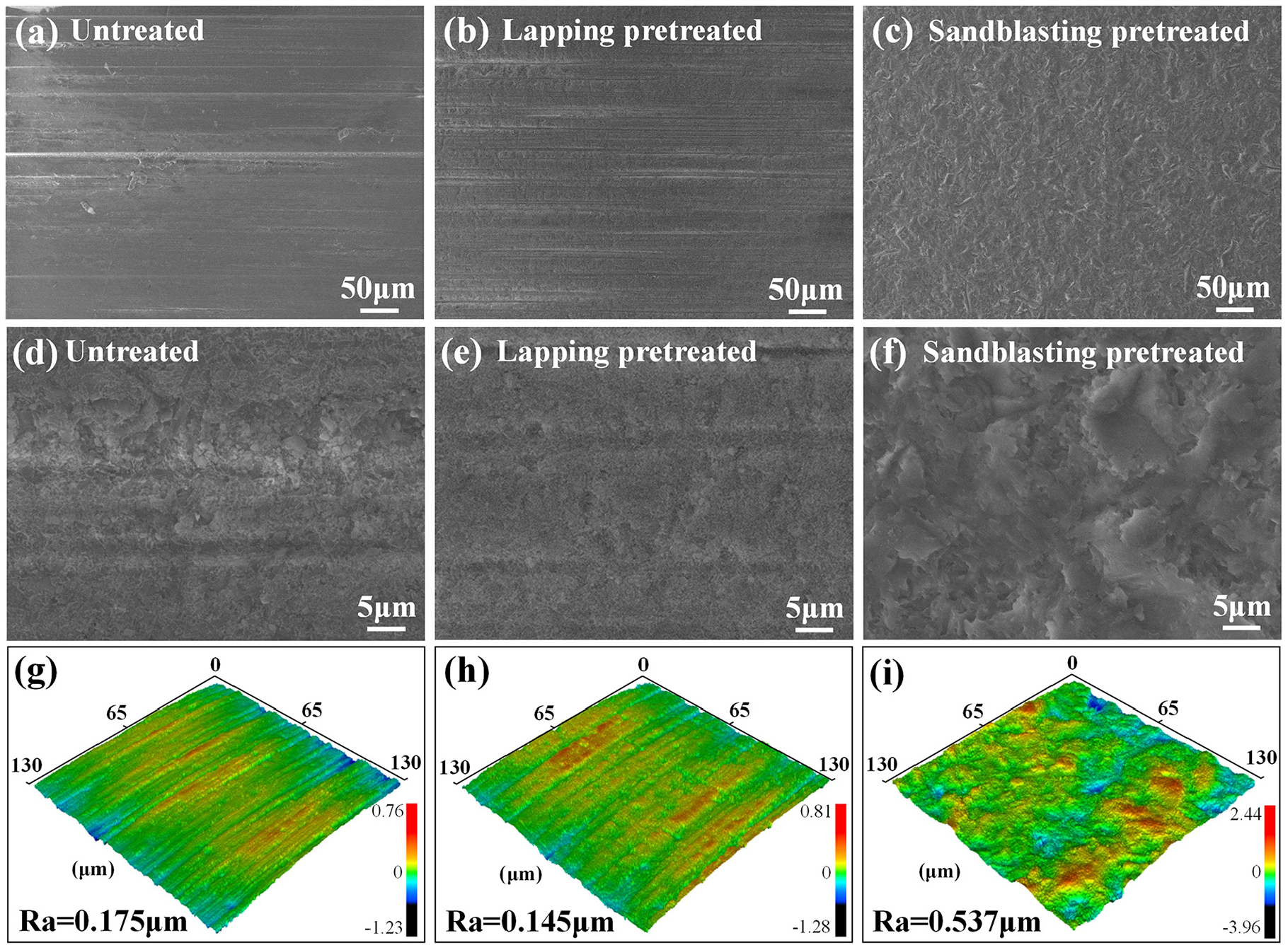
(a–f) SEM micrographs and (g–i) 3D morphology of silicon nitride ceramic substrate (a, d, and g) untreated specimen,(b, e, and h) lapping pretreated specimen, (c, f, and i) sandblasting pretreated specimen.
Fabrication of CVD diamond abrasive tools
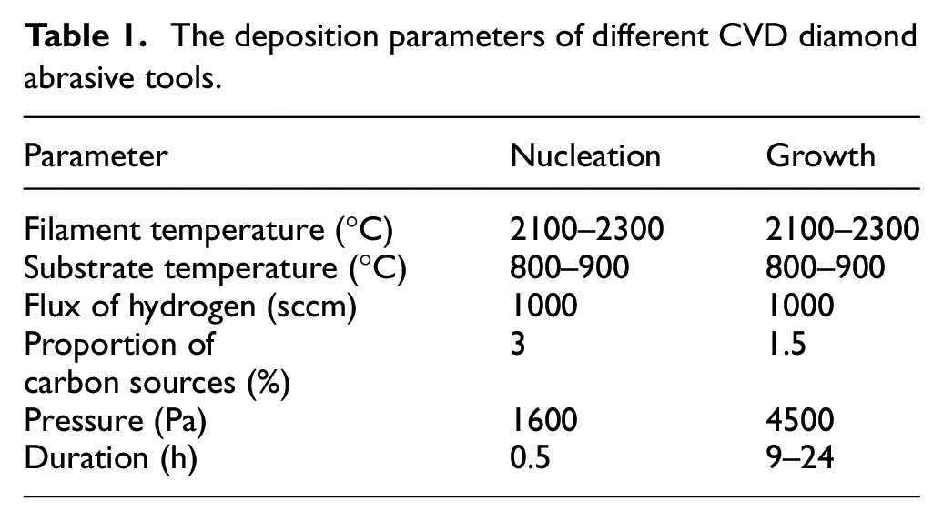
The lapping and sandblasting pretreated silicon nitride substrates were put into the hot filament chemical vapor deposition equipment (HFCVD350, Shanghai Jiao Tong University) to deposit the diamond abrasive layer and fabricate the diamond abrasive tools. Another difficulty in fabricating CVD diamond abrasive tools is how to deposit diamond abrasives with large particle sizes. Therefore, a lower carbon source concentration and a longer deposition time are used to fabricate diamond abrasive tools with different particle sizes. The deposition parameters are shown in Table 1, and the deposition time was varied to fabricate diamond abrasive particles with different sizes.
The deposition parameters of different CVD diamond abrasive tools.
Grinding tests
To evaluate the grinding performance of CVD diamond abrasive tools with different parameters, the cemented carbide drawing dies are selected as grinding workpieces, and the grinding quality and grinding life are the evaluation basis. Figure 2 shows the schematic diagram and processing scenario of the cemented carbide grinding test. The specific material is tungsten carbide with 6% cobalt content (YG6) and a hardness of 90 HRA, and the diameter of the workpiece inner is 18 mm. The purpose of this grinding test is to evaluate the precision grinding effect of CVD diamond grinding tools, so a lower feed rate is used. The feed rate and rotate speed of diamond abrasive tools are 0.5 μm/min and 500 r/min, respectively, and the rotate speed of the workpiece is 100 r/min. The grinding test is carried out in a precision high-speed die trimming machine. The surface morphology of the diamond abrasive tools and workpiece was observed after grinding to determine the grinding quality and grinding life, and the observations were made every 2 min.
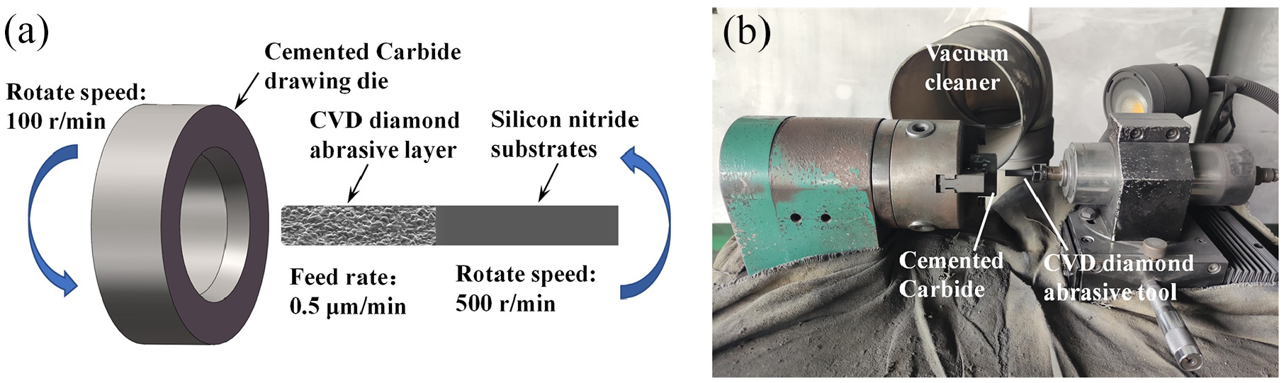
The cemented carbide grinding test: (a) schematic diagram and (b) processing scenario.
Results and discussion
Surface and cross-sectional morphologies
The surface and cross-sectional morphologies of the abrasive layer for different diamond abrasive tools were observed, and the results are shown in Figure 3. The diamond abrasive particles grown by the sandblasting pretreated substrate are 6–8 μm, which are larger than the 5–7 μm abrasive particles grown by the lapping pretreated substrate. The diamond abrasive deposited on different pretreated substrates have different sizes, this is because the sandblasting pretreatment can increase the surface roughness of the substrate, thereby providing more nucleation sites for diamond deposition. Then the diamond growth rate has been accelerated. For the specimen with sandblasting pretreated substrate, the effect of substrate surface roughness on diamond growth is decreased when the deposition time is 24 h. Meanwhile, the diamond abrasive particles deposited by the two pretreated substrates were almost the same, and the sizes were 16–20 μm as seen in Figure 3(c) and (d). From the cross-sectional view, it can be seen that the surface particles of the four specimens were protruding, and the protruding tips could be used for grinding. Meanwhile, the surface of the ceramic substrate changes after lapping pretreatment is smoother, so the growth surface of the diamond abrasive grain layer is relatively straight. The surface of the ceramic substrate pretreated by sandblasting is more tortuous, and the growth surface of the diamond abrasive layer is more tortuous, which could be increasing the effect of mechanical interlock. In addition, the fine abrasive particles of 5–8 μm are about W7 size, and the coarse abrasive particles of 16–20 μm are about W20 size. Therefore, according to the different pretreatment methods of lapping and sandblasting and the different abrasive particle sizes, the four specimens were named L7, L20, S7, and S20, respectively.
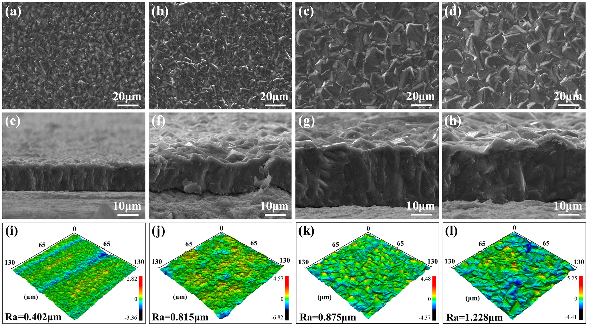
Surface, cross-sectional morphology, and 3D morphology of diamond abrasives with different deposition processes:(a, e, and i) L7, (b, f, and j) S7, (c, g, and k) L20, and (d, h, and l) S20.
The 3D morphology of the diamond abrasive surface with different processes were also shown in Figure 3. For the lapping pretreatment tools, the machining groove marks were still present in the surface of the diamond abrasive layer for the L7 specimen, and the groove marks disappeared when the deposition time reached 24 h. For the specimens pretreated by sandblasting, irregular bumpy undulations caused by sandblasting have existed on the surface of the diamond abrasive layer when the deposition time was 9 h, and the bumpy areas were covered by the abrasive layer after the deposition time reached 24 h. Besides, the surface roughness of Ra values was counted for the four diamond abrasive tools. The Ra values of sandblasting pretreatment tools were higher than that of lapping pretreated tools under the same abrasive particles. This is because sandblasting pretreatment increased the roughness of the substrate surface and inherited to the surface of the diamond abrasive layer. The higher surface roughness value has increased material removal efficiency during the grinding process, and the gap between the abrasive particles has facilitated the transfer of dust.
Measurement of residual stress and adhesion strength
Figure 4 shows the Raman observation results of the abrasive particles for different diamond abrasive tools, it can be seen that the Raman curves of the four specimens are in substantial agreement. The 1332.5 cm−1 peak representing the diamond sp 3 phase is relatively high, and the 1560 cm−1 peak representing the graphite sp 2 phase is relatively low, indicating that the diamond has higher purity and less graphite content. Moreover, the sp 3 peaks of synthetic diamond are existed migration phenomenon owing to the residual stress 16 or defectiveness in diamond. 17 The diamond peaks of lapping pretreated specimens have shifted to 1331.5–1332 cm−1, which means those specimens have tensile stress and it is detrimental to the adhesion strength between abrasive layer and substrate. For the specimens with sandblasting pretreatment, the diamond peak overlaps with the standard peak of 1332.5 cm−1,18 which means the sandblasting pretreatment does not produce stress and the adhesion strength between the abrasive layer and substrate will not be weakened.
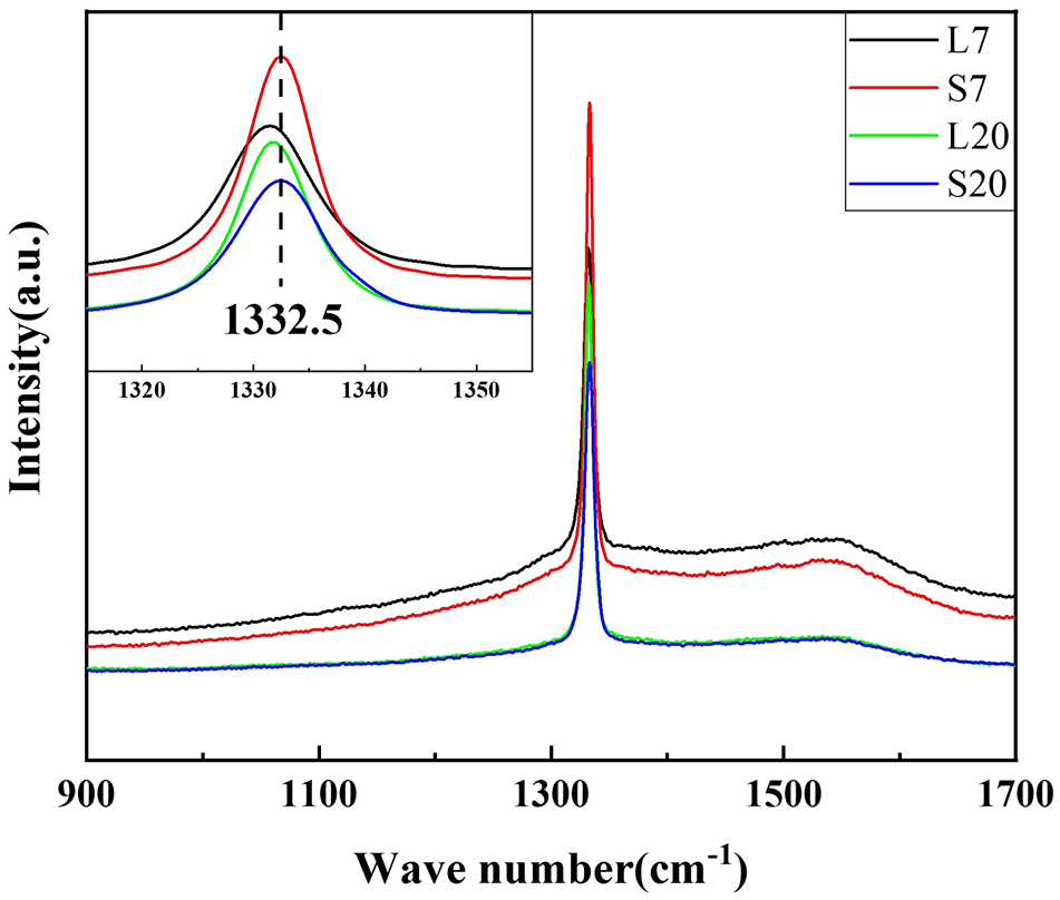
Raman curves of different diamond abrasive tools.
To further evaluate the adhesion strength between the abrasive layer and the substrate, an indentation test was conducted on the head face of the diamond abrasive tool using an HRA-1500 Rockwell hardness test with a load of 1000 N, and the indentation morphology is shown in Figure 5. For the specimens with the same pretreatment method, the abrasive layer with higher thickness has a lower creaking area owing to the better crack expansion resistance. Meanwhile, the creaking area of sandblasting pretreated specimens is significantly smaller than that of the lapping pretreated specimens. For the abrasive particle with W7 size, the creaking radius has reduced from 398 to 216 μm, which was reduced by 45.7%. For the abrasive particle with W20 size, the crack expansion resistance has strength and the creaking radius is reduced from 159 to 144 μm, which the reduced ratio has changed to 9.4%. In addition, the surface of the CVD diamond abrasive tool after lapping pretreatment is cracked after the Rockwell indentation test, indicating that its toughness is poor and it is easy to crack under stress. After sandblasting pretreatment, the interface between the diamond abrasive layer and the substrate is more tortuous, which effectively blocks the expansion of cracks. The indentation results show that the cracking surface is also more tortuous, and the crack length is significantly smaller than that of lapping pretreated specimens. Therefore, sandblasting pretreatment can effectively improve the adhesion strength of the abrasive layer and the substrate as well as the resistance to crack expansion.
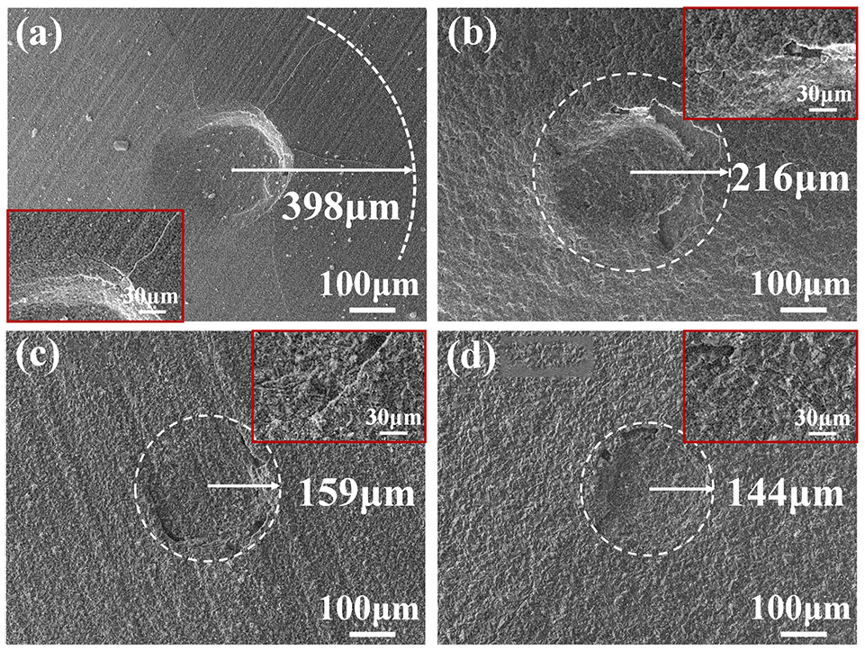
Rockwell indentations of different diamond abrasive tools: (a) L7, (b) S7, (c) L20, and (d) S20.
Cemented carbide grinding test of different CVD diamond abrasive tools
Grinding results analysis
The surface morphology of four CVD diamond abrasive tools after grinding cemented carbide for 5 min was observed, and the results are shown in Figure 6. For the diamond abrasive tools of W7 size, the surface of the abrasive layer has presented the abrasive dust accumulation phenomenon. For lapping pretreatment tools of Figure 6(a), the abrasive dust is mainly distributed presented long flake shape, which is corresponding to the grooves of the untreated specimen in Figure 1(a). Meanwhile, the abrasive dust of the sandblasting pretreatment tools is mainly distributed in the pits that originate from sandblasting. Due to the accumulation of abrasive particles, the grinding process gradually becomes a friction process between the abrasive particles and the workpiece, which reduces the grinding effect. It shows that the grinding capacity of the abrasive tools with a small particle size is insufficient, and the grinding capacity is reduced due to the accumulation of abrasive dust on the surface. Furthermore, the diamond abrasive tools of W20 size have large particles and sufficient space for dust between adjacent particles, 19 and most of the dust can be discharged from the surface. Therefore, only a small of dust adheres during the grinding process, and the accumulation of abrasive dust will not occur, thus the good grinding effect can be maintained continuously. The abrasive particle with a large size is more suitable for grinding.
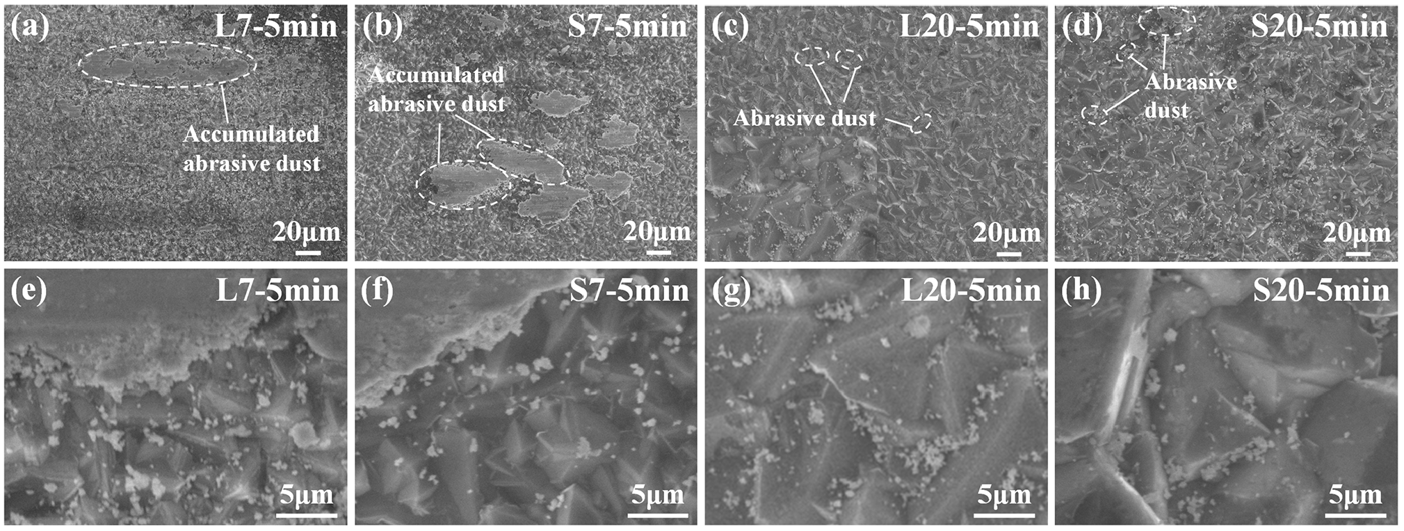
Surface morphology of the grinding abrasive tools after grinding for 5 min: (a and e) L7, (b and f) S7, (c and g) L20, and(d and h) S20.
The energy dispersive spectroscopy (EDS) analysis results of the abrasive particles after grinding are shown in Figure 7(a) to (d). The accumulated abrasive dust on the surface of the L7 and S7 grinding tools is overlapping with the positions of the W and Co elements and blocks the positions of the C element, so the accumulated dust is mainly the ground tungsten carbide dust. Moreover, the position of the abrasive dust coincides with the O element, indicating that the abrasive dust has been partially oxidized and is broken by the workpiece. The less abrasive dust presented in L20 and S20 tools is also detected as the above components. Meanwhile, the content of the O element of W20 tools is similar to the W7 tools in the condition of less abrasive dust, and the positions of the O element are completely coincident with abrasive dust, indicating that the abrasive dust is completely oxidized and was ground from the workpiece. The EDS results can assist in illustrating that the W20 abrasive tools have a better grinding ability and dust removal capacity.
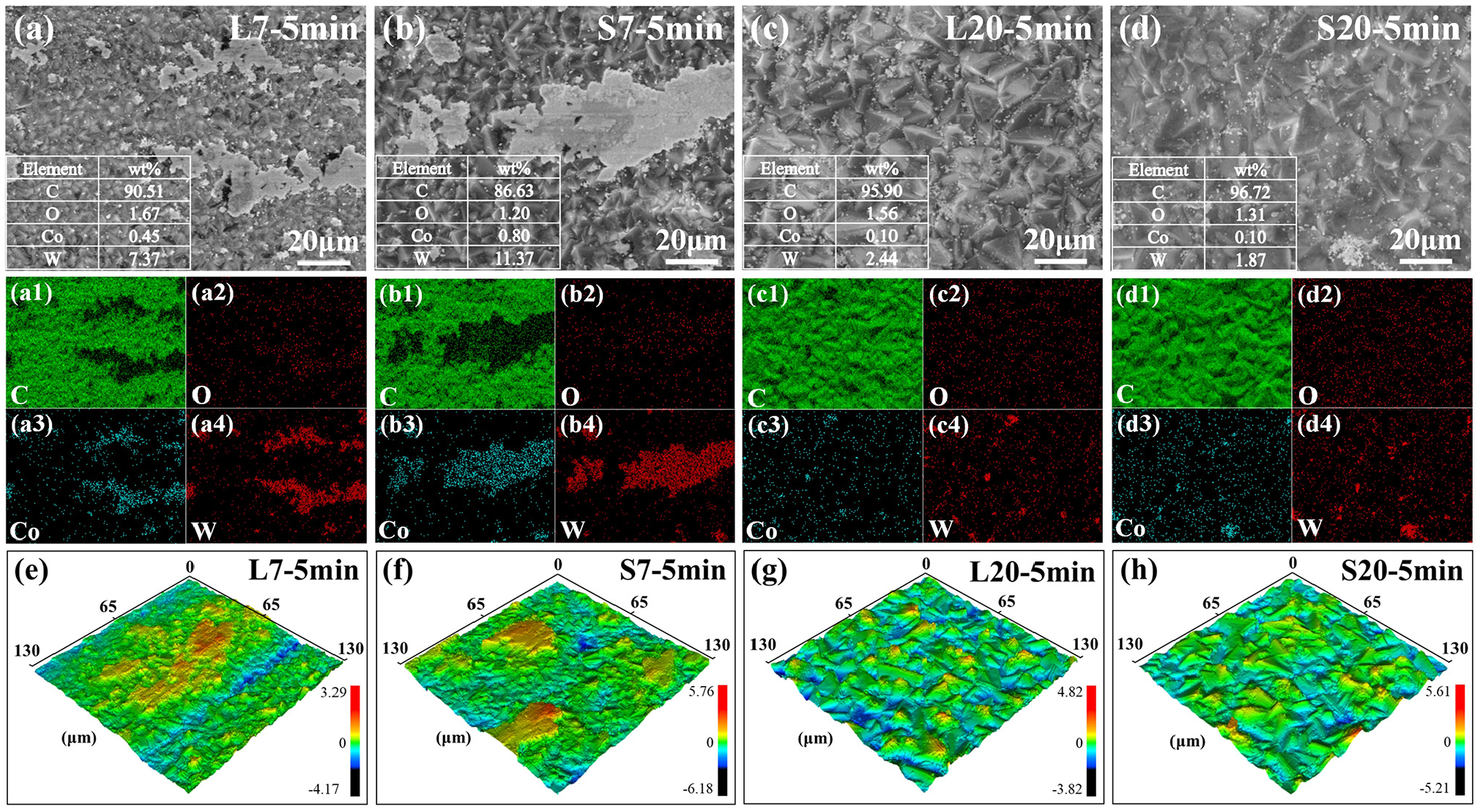
EDS result and 3D morphology of the surface after grinding 5 min of the four tools: (a and e) L7, (b and f) S7, (c and g) L20, and (d and h) S20.
From the above results, effective grinding is maintained for the W20 tools, and the grinding efficiency of W7 tools has decreased due to the accumulation of abrasive dust. To further understand the grinding behavior of different diamond abrasive tools, 3D morphology observations were carried out on the four types of tools after grinding, and the results are shown in Figure 7(e) to (h). For the W7 tools, the height of the dust accumulation position is significantly higher than the height of the diamond abrasive layer, which can indicate that the direct contact between the accumulated dust and the cemented carbide is disappeared, and the dust existed between the diamond abrasive particles and the workpiece has reduces the grinding effect. For the W20 tools, there is no accumulated dust on the surface, and only the particle dust adheres to the surface of the diamond abrasive particles. Therefore, when the grinding time reaches 5 min, the grinding effect of W7 abrasive particle tools is reduced, and the grinding effect of W20 abrasive particle tools is still better.
Grinding life comparison
In addition to the grinding effect, the grinding life is also an important evaluation index for grinding tools. The four grinding tools were ground continuously until the abrasive layer shedding to evaluate their grinding life, and the failure times were 8 min for the L7 tool, 12 min for the S7 tool, 14 min for the L20 tool, and 20 min for the S20 tool, respectively, as shown in Figure 8. The comparison of failure time shows that the life of W20 tools is higher than that of W7 tools under the same pretreatment method, which is owing to the space between the abrasive particles of W7 tools being too small and the dust holding space being insufficient. During the grinding process, the dust adheres to the surface of the tool and continues to accumulate, and change the contact behavior between the abrasive particle layer and the cemented carbide from grinding to friction. Finally, the increase in friction causes local stress generation, which leads to the shedding of the abrasive layer and reduces the grinding life.
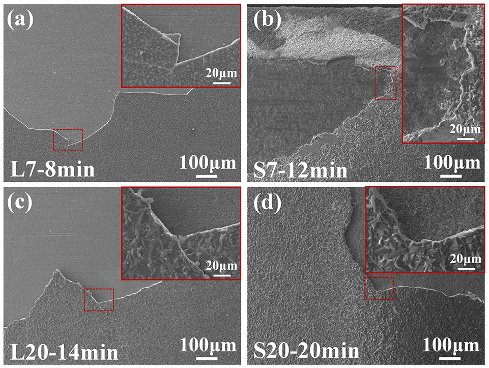
The failure morphology of four tools after grinding: (a) L7, (b) S7, (c) L20, and (d) S20.
From the failure morphology of different tools, the pretreatment method has produced a significant effect on the failure behavior. Under the same abrasive particle size, the grinding life of the sandblasting pretreated tools is longer than that of the lapping pretreatment tools. The fracture parts for the abrasive layer of the lapping pretreatment tools are very straight, which is a brittle fracture, and it can be seen from the local magnification that there is crack extension at the fracture parts for the abrasive layer. For the two kinds of sandblasting pretreated abrasive tools, the broken part of the abrasive layer is tortuous. It can be seen from the partially enlarged view that the fracture spreads along the grain boundary direction, that is, the grain boundary has a certain obstructive effect on the crack propagation, and there is no obvious crack propagation on the surface of the abrasive layer. Therefore, combined with the previous section, the S20 tools not only have high adhesion strength and crack propagation resistance but also have the advantage of better dust removal capacity, which shows the highest grinding life.
Grinding performance comparison of CVD diamond abrasive tool and electroplated diamond abrasive tool
To further illustrate the grinding performance of CVD diamond abrasive tools, CVD diamond abrasive tools and electroplated diamond abrasive tools were subjected to cemented carbide grinding tests to compare their grinding life and grinding quality. The tool of S20 with the better grinding ability and dust removal capacity in the previous section was selected for comparison with the electroplated diamond abrasive tool. The abrasive size of the electroplated diamond abrasive tool remains the same as that of the CVD diamond abrasive tool, both with W20 size, and the electroplated diamond abrasive tool is named ED20 in the following.
Surface morphology and roughness of electroplated diamond abrasive tool
Figure 9 shows the SEM and 3D morphology of the ED20 tool. The abrasive particle size of the ED20 is about 18 μm, which is similar to the size of the diamond abrasive for the S20 tool in Figure 3. In addition, the diamond abrasive particles for the ED20 are synthesized by the high-temperature and high-pressure (HTHP) method and further crushed, so the abrasive particles show an irregular shape and have more defects. The diamond abrasives vary in their shape, size, orientation, and distribution on the tool surface, resulting in variations in the protruding height from the tool surface. The surface roughness Ra value of the ED20 is 2.01 μm, which is 63.4% higher compared with 1.23 μm of the S20 tool. The thin electroplated layer leads to high exposure of abrasive particles and large surface roughness than that of the CVD diamond abrasive tool.
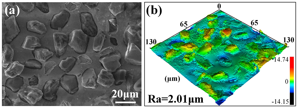
Surface morphology of electroplated diamond abrasive tool with W20 particle size: (a) SEM morphology and (b) 3D morphology.
Comparison of grinding results
In the previous section, the tool of S20 is failed after grinding for 20 min. To compare the grinding performance, the grinding time is controlled within the failure time. In the comparative grinding test of S20 and ED20 tools, the grinding times of 5, 10, and 15 min were selected to compare the surface morphology of tools and surface roughness of the workpieces at different grinding stages. The grinding experimental parameters were the same as in the previous section.
Figure 10 shows the surface morphology of S20 and ED20 tools at different grinding times. When the grinding time is 5 min for the CVD abrasive tool, only some cemented carbide dust remained on the surface and the distribution was relatively uniform, and the diamond abrasive particles were not worn and broken. After 10 min of grinding, a large amount of abrasive dust remained on the surface, but there was no accumulation of abrasive dust, and a large amount of diamond abrasive particles was exposed to continue the grinding behavior. When the grinding time is increased to 15 min, a large amount of abrasive dust covered part of the diamond abrasive particles. At the same time, some of the abrasive particles began to wear, which appeared in the form of abrasion wear, but there are still a large number of intact abrasive particles and the effective grinding behavior could be continued.
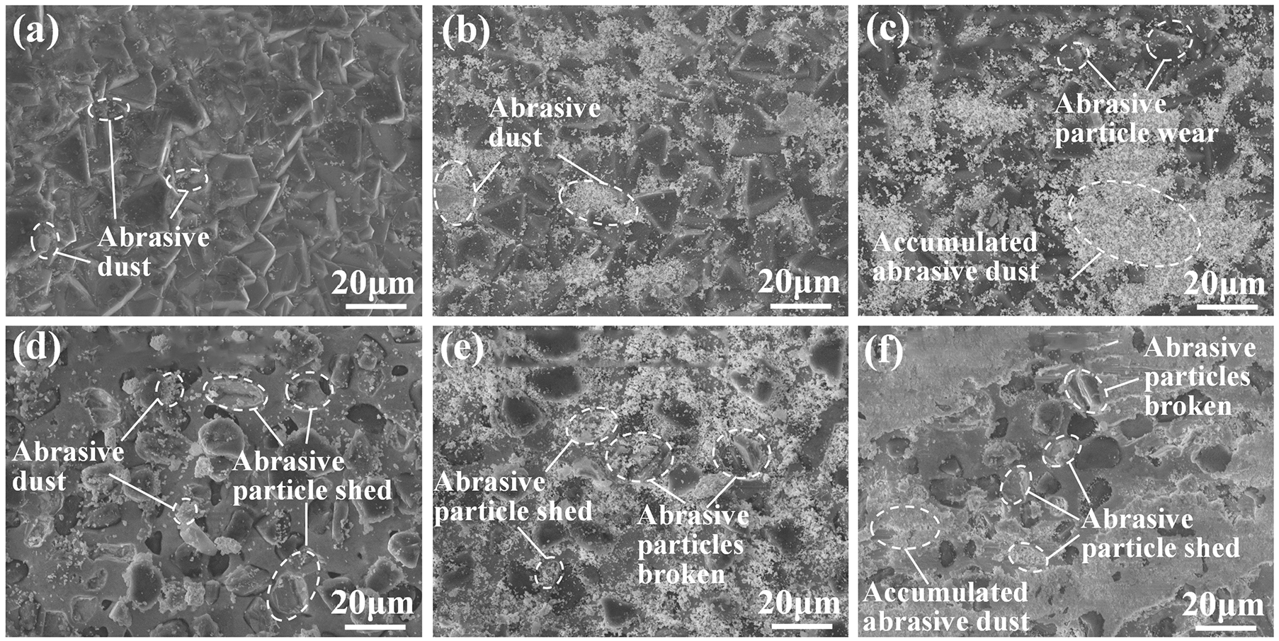
Surface morphology of S20 and ED20 tools after grinding for different times: (a) S20-5 min, (b) S20-10 min,(c) S20-15 min, (d) ED20-5 min, (e) ED20-10 min, and (f) ED20-15 min.
As the electroplated diamond abrasive tool of ED20, after 5 min of grinding the cemented carbide, the granular some clustered abrasive dust has remained on the surface, and some of the diamond abrasive particles begin to fall off. This is because there is a physical embedding effect between the electroplated diamond abrasive particles and the matrix, and the shape of the diamond abrasive particles is different, causing some of the particles to fall off in the role of local stress off. After 10 min of grinding, a large amount of abrasive dust remained on the surface of the diamond abrasive tool, and the phenomenon of abrasive particle breaking and shedding could be observed. Moreover, the plating void after the abrasive particles shed has been filled by the abrasive dust and embedded blockage occurs. With the abrasive particles breaking and shedding, the electroplated diamond abrasive tool starts to fail and the grinding effect is weakened. After the grinding time increased to 15 min, a large number of abrasive particles are fell off and broke, and the abrasive dust continued to accumulate. The accumulated abrasive dust covered the abrasive particles, and the contact between the abrasive particles and workpiece had changed from grinding to friction so that the abrasive tool lost the grinding effect.
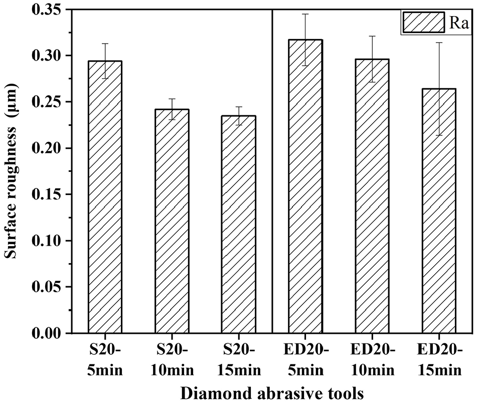
The roughness of the workpiece after grinding by the two kinds of abrasive tools was measured using a roughness measuring instrument (SJ210, Mitutoyo), and the measured values are shown in Figure 11. The surface roughness values of the workpieces in both tests are decreased as grinding proceeded. When the grinding time is 5 min, the Ra value grinding by the ED20 was higher than that of the S20, because of the high Ra value of the electroplated diamond abrasive tool, which led to the high surface roughness of the machined part after grinding. When the grinding time reached to 10 min, the Ra value of the machined surface by the S20 tool was rapidly reduced to 0.242 μm. Meanwhile, the shape of the abrasive particles was complete and no wear occurred, and the grinding efficiency was high and the roughness decreased significantly. However, the Ra value of the surface grinding by ED20 tool was decreased less, which is only 0.296 μm, because the electroplated diamond abrasive particles were broken and fell off, resulting in the decrease of grinding effect of abrasive tools.
Surface roughness values of cemented carbide after grinding by the tools of S20 and ED20 at different times.
After 15 min of grinding, the Ra value of workpiece grinding by the S20 tool was decreased to 0.235 μm, which was not obvious compared with the previous stage. The decrease of Ra at this stage was mainly due to the blunting of the CVD diamond abrasive particles, and the sharp part of the particles was smoothed out, which made the surface roughness value of the machined parts decrease. Meanwhile, the Ra value of workpiece grinding by the ED20 tool has dropped significantly, but the Ra error value is high, and the Ra value varies greatly and shows unevenness. At this time, the shed and broken of electroplated abrasive particles are obvious, and there is much accumulated dust on the surface of abrasive particles and the tool of ED20 has lost its grinding effect. The surface roughness of the workpiece is reduced by the extrusion of abrasive dust under the action of friction. Therefore, the effective grinding time of the ED20 tool can be regarded as 10 min, and the effective surface roughness after grinding is 0.296 μm. In summary, the surface roughness of CVD diamond abrasive tools is reduced by 25.96% compared with that of electroplated diamond abrasive tools.
Analysis of the wear mechanism
Figure 12 shows the wear mechanism of the CVD diamond abrasive tool and electroplated diamond abrasive tool. For the CVD diamond abrasives tool, the difference in the surface shape of grinding particles is smaller. In the early stage of grinding, the grinding force on the abrasive particles is more even, and the number of abrasive particles per unit area is more than that of electroplated diamond abrasive particles. Because only a portion of the particles on the surface of ED20 interacts with the workpiece, the average grinding force on the abrasive particles of the S20 tool is less than that of the ED20 tool. At the same time, the adhesion strength between the abrasive layer and the substrate in CVD diamond abrasive tools is high, and the abrasive particles are not easy to fall off. As the grinding progresses, only some of the abrasive particles are worn out, and the grinding force between different particles has changed after wear. However, since the abrasive particles do not fall off, the change of average force for the abrasive particles is relatively small, which makes CVD abrasive tool has a longer grinding life.
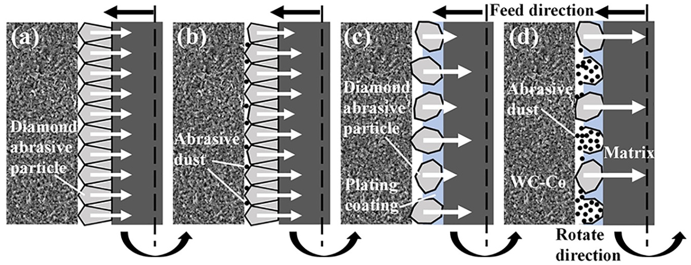
Schematic diagram of the wear mechanism of S20 and ED20 grinding tools: (a and c) early stage of grinding and (b and d) after grinding.
For electroplated diamond abrasive tool, the irregular shape of the surface causes a large difference in the contact area and grinding force between the abrasive particles and the cemented carbide at the early grinding stage, which is shown in Figure 12c. As the grinding progresses, some abrasive particles begin to fall off under the action of the local stress, and the abrasive dust generated during the grinding process quickly fills the void between the abrasive particles. Meanwhile, the abrasive particles in contact with the cemented carbide during the grinding process will decrease after part of the abrasive particles fall off. As a result, the average grinding force experienced by the abrasive particles increases, and the increase in the grinding force causes the abrasive particles to fall off quickly. Suzuki and Konno 20 reported that the abrasive particles are easy to fall off and fail as the grinding force of a single abrasive particle continues to increase, which is consistent with the failure mechanism of electroplated diamond abrasive tools in this study. Therefore, the abrasive particles of the ED20 tool are easy to fall off during the grinding process, and the grinding force of the unshed abrasive particles increases when other abrasive particles are shed, so that the grinding life is significantly shorter than that of CVD diamond abrasive tools.
Conclusion
CVD diamond abrasive tools were fabricated using the HFCVD method on the silicon nitride ceramic substrate pretreated by lapping and sandblasting. The effect of the pretreatment method and abrasive particle size on the basic properties such as morphology and adhesion strength are studied, and the cemented carbide grinding test is proceeded to evaluate the grinding performance of the CVD diamond abrasive tool and electroplated abrasive tool. The summary is listed as the following:
The sandblasting pretreatment could increase the surface roughness of the nitride silicon substrate and provide sufficient nucleation for the growth process of diamond abrasive particles. Meanwhile, owing to the sandblasting pretreatment can reduce the residual stress of the abrasive layer, the adhesion strength between diamond abrasive particle layers and the substrate of the specimen is higher than the lapping pretreated specimen, and the resistance to crack extension was also better.
Grinding tests were conducted on diamond abrasive tools that pretreated with the lapping and sandblasting method. The tools with fine particles have the phenomenon of abrasive dust accumulating on the surface, which leads to a decrease in the grinding ability. Meanwhile, the tools with coarse particles have a better grinding ability because the dust is not easy to adhere to the surface. The abrasive tool with coarse particles fabricated after sandblasting pretreatment has the longest grinding life.
For the CVD diamond abrasive and electroplated abrasive tools with the same particle size, the abrasive particle of electroplated diamond abrasive tools is prone to shedding and breakage during the grinding process. The CVD diamond abrasive tools only have abrasion wear during grinding, which leads to the passivation of abrasive particles. After passivation, the abrasive tools still have the grinding effect, and the surface roughness of the workpiece is lower than that of electroplated diamond abrasive tools.
Footnotes
Declaration of conflicting interests
The author(s) declared no potential conflicts of interest with respect to the research, authorship, and/or publication of this article.
Funding
The author(s) disclosed receipt of the following financial support for the research, authorship, and/or publication of this article: This research is supported by the National Natural Science Foundation of China (No. 52175424).