
Abstract
Plunge milling has significantly improved the rough machining efficiency of 3D impeller channels. However, in conventional plunge milling cutter position planning, interferences occurring at the end of every cutter position due to the sudden increase of radial depth is inevitable. This can seriously compromise the service life of the machine tool and cutter, and also reduce the efficiency at the interferential phase. This study optimised the tool path cutter axis vector of conventional rough machining of 3D impeller variable-axis plunge milling, thus making the angle between the normal vector of workpiece surfaces at the cutter contact point, and the cutter-axis vector of the adjacent tool position, gradually increase from the outlet to inlet on a very small scale. Based on this, an iterative algorithm for the tool centre position and cutter safety height was obtained, thus making the hub allowance of the optimised tool path for plunge milling as small as possible without affecting subsequent machining by avoiding the interferential phenomenon. Finally, the proposed method was verified by relevant numerical examples.
Keywords
Highlights
In order to avoid the interferential phenomenon in the rough machining of variable axis plunge milling of 3D impeller, cutter axis vector optimisation was performed for the tool position for variable axis plunge milling, in which the angle between the normal vector for workpiece surface at the cutter contact point and the cutter-axis vector of adjacent tool position was increased gradually from outlet to inlet at the smallest scale.
An iterative algorithm for tool centre position and safety height for the cutter was provided, thus making the hub allowance of the optimised tool path for plunge milling as small as possible without affecting the subsequent machining on the premise of avoiding the interferential phenomenon.
Introduction
Centrifugal compressors are an important product in the equipment manufacturing industry, and are broadly applied in fields such as metallurgy, petrochemistry, natural gas transportation and air separation. A centrifugal 3D impeller is the core component of a centrifugal compressor, and many studies have attached high importance to its processing efficiency and manufacturing accuracy. For 3D impellers, about 70%–80% of the material needs to be removed at the rough machining stage, 1 indicating that improving the processing efficiency of the impeller should start with rough machining.
The development of 3D impeller rough machining originates from traditional 5-axis side milling. Young 2 proposed a method for 3D impeller channel rough machining with a layered side milling strategy which overcomes the collision issue between the cutting tool and impeller. Lim 3 proposed a statistical method to optimise the rough cutting parameters in traditional 5-axis side milling by response surface methodology, and an efficient strategy to divide the cutting region which significantly improved 3D impeller rough machining efficiency. Fan et al. 4 proposed an approximated blade with ruled surfaces as a simpler target for impeller rough machining to solve the free-form blades side milling problem. Fan et al. 5 calculated the largest cutter and smallest tool path length with an efficient impeller 5-axis machining method based on regional milling, which further improved the rough machining efficiency of 3D impeller side milling. Zhou et al. 6 moved the five-axis machining of impellers towards a new paradigm. A tool-path generation method that considers both the machining efficiency and the aerodynamic performance of impellers is proposed for five-axis flank milling, which mitigates the negative effects on the aerodynamic performance of impellers by blindly enhancing processing efficiency.
Undoubtedly, the processing stability of 3-axis milling is better than 5-axis milling, and based on this, Pei et al. 7 proposed a novel 3D impeller rough machining method named 3 + 2 axis high-speed milling. This is where two rotation axes of the 5-axis machine tool are locked and only three linear axes participate in the linkage cutting during processing. Feng et al. 8 proposed a tiling micro-arc mapping algorithm for rough machining of impellers, which maps the three-dimensional boundary to the two-dimensional parameter domain plane. This succeeded in making the processing area in 3 + 2 axis high-speed milling more precise. In this way, high efficiency parameters can be used, and processing efficiency is greatly improved. However, impeller manufacturers still demand more.
In plunge milling, the tool is mainly subjected to axial force, while its rigidity in the axial direction is far better than that in the radial direction. In addition, Ozoegwu and Eberhard 9 developed a method for defining and analysing the geometry of cylindrical milling tools with various free-form helix angle variations, by which the axial force that occurred during plunge milling could be reduced on a large scale. However, a problem persists whereby the cutting force in plunge milling is still large and unstable if the process parameters are not correctly selected. Furthermore, plunge milling is prone to back-off and tool radial runout, which significantly impacts the processing efficiency and cutter life. To resolve this issue, Ventura and Hassui 10 developed a cutting force model based on process kinematics and the tool’s special features to predict the mean forces generated during the plunge operation. This model can reduce the flank wear of the cutter to a certain degree. Liang et al. 11 proposed an original approach to schedule the feed-rate in open blisk multi-axis plunge milling, based on the material removal rate, to smooth the variance in cutting forces and torque. Li et al. 12 established a plunge milling force model based on the combination of analysis and a three-dimensional finite element method to obtain the modified cutting layer parameters and optimise the cutting force. Gao et al. 13 established an instantaneous chip thickness model which considers the tool radial runout effect and a plunge milling force prediction model. A stability lobe diagram of the plunge milling process was also obtained in this research which could provide optimised process parameters for plunge milling. Huang et al. 14 investigated the influences of the tool engagement angle and tool geometry on tool wear in plunge milling, based on multiple sets of machining tests. The results showed that an optimal engagement angle can be achieved when the radial distance is equal to the tool radius, and the tool life of an insert without cutting edge chamfer is 3.6 times that of an insert with cutting edge chamfer. This could be useful for manufacturers to optimise tool geometry and machining parameters. In addition, Cheng et al. 15 proposed another idea to solve the impeller problem in plunge milling by designing a plunge milling tool with a finite element method. The strength of the tool and the stability of the plunge milling were then verified through static and modal analysis. Furthermore, experiments on the titanium alloy were also conducted via a novel designed tool to analyse and verify the rationality of the tool design and strength. Based on this, the plunge milling vibration problem caused by the large cutting force could be alleviated. In addition, Zhang et al. 16 conducted experimental studies and theoretical calculations on the tool lives of free-cutting steel. The conclusion that the free-cutting steel with added Bi (MB) presented the best tool life of about 9200 s and 5200 s at a speed of 150 and 200 m/min gives a good guide for cutting parameter selection in impeller plunge milling. As a result, compared with end and side milling methods, plunge milling is the more stable process.
In view of its potential advantages, plunge milling has attracted extensive global attention recently, and is already being applied in blisk machining. Ren et al. 1 applied a 4-axis plunge milling method for open blisk rough milling in 2009. Sun et al. 17 proposed a new plunge milling tool path generation method using medial axis transformation which could be used to control the radial depth to improve the cutting efficiency and cutter life. As for the cutting mode, in conventional plunge milling, the tool axes of every tool position are parallel to each other. This mode is called fixed axis milling, 18 or 3+2 axis plunge milling. Before processing, the angle of the two rotation axes for the 5-axis machine tool is determined and locked, and during processing, only three straight axes are involved in the cutting process. If the tool axes of every tool position are not parallel, this is known as variable axis plunge milling. 19 Zhang et al. 20 created a layered model of impeller variable axis plunge milling which considered the maximum tool and tool length, thus improving the large machining allowance in impeller single layer plunge milling. Han et al. 21 conducted research on plunge cutter selection and a tool path generation algorithm and applied it to variable axis plunge milling of free-form surface impeller channels. Additionally, during plunge milling, the tool axis sometimes changes continuously. 22 This method may also be classified as 5-axis end milling, but is generally called continuous variable axis plunge milling. In rough plunge 3D impeller milling, no matter which way the slotting take place, the interferential phenomenon occurring at the end of each cutter position is inevitable, which can seriously compromise the service life of both the machine and cutting tools. Sun et al. 23 attributed this phenomenon to the sudden increase of radial depth occurring at the end of the plunging phase, and presented its influences on the service life of both the machine tool and the cutter. A solution was also proposed, based on decreasing the plunge depth to avoid radial depth increasing at the end of the plunging phase. However, although suitable for the plunge milling of axial flow blades, it is not suitable for plunge milling a centrifugal impeller, as it would leave a large machining margin on the hub surface which would cause problems in subsequent hub finish machining. Dong et al. 24 established an in-process 4-axis plunging model which could represent the part’s geometry during plunging so that the residual and overcut of the material could be evaluated. It is a pity that the residual material considered in this research was based on a projection of the tool envelope surface on one section of the tool axis direction, as the interference of residual material at the side of the workpiece on the next tool position is predictable. However, the slotting depth and interference of residual material at the bottom of the workpiece on the next tool position is ignored. Huang et al. 25 developed a new plunge milling toolpath generation method with adaptive intervals to restrict the maximum scallop height within a given value, which could relieve the interference at the end of every cutter position due to a sudden increase of radial depth, to a certain degree. However, the cusp of the constant scallop is still there, and the given value is not small enough to completely eliminate the interference at the end of each cutter position. There is no other research available concerning this problem.
Interference during 3D impeller plunge milling
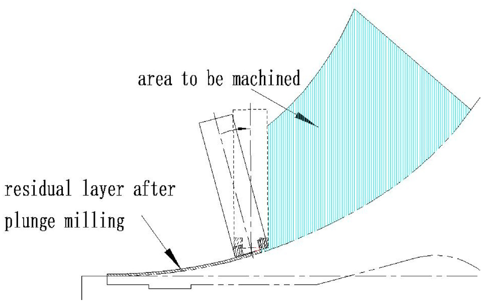
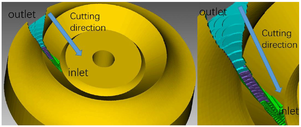
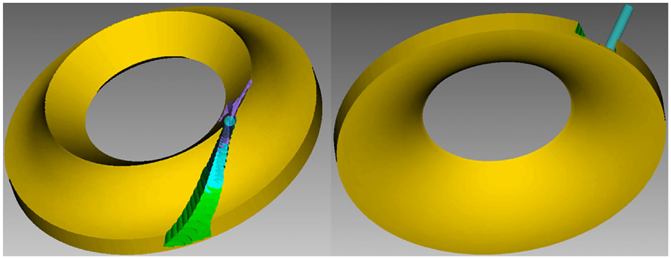
The interferential phenomenon refers to the difficulty in tool feeding during the plunge milling process, resulting from the part without a cutting blade at the bottom of the flat-bottomed cutter, as shown in Figure 1. In industrial production, variable axis milling is the most commonly used method for the rough milling of 3D impellers, because of its high cutting efficiency. However, during programming the interferential tool position cannot be avoided (Figure 2). This is because during plunge milling, due to the distortion of the impeller hub surface, even if the planned radial cutting width is less than the cutting blade length at the bottom of the tool, there will still be a section without a cutting blade involved in cutting the residual layer of the hub left by the previous tool position when the bottom part of the flat-bottomed cutter is close to the hub surface (Figure 3). Thus, interference occurs. Even if all the cutting blades passed through the bottom surface cutter centre, due to the zero-cutting speed at the centre, interference may still occur, resulting in cutting trouble accompanied by increased noise and tool vibration.
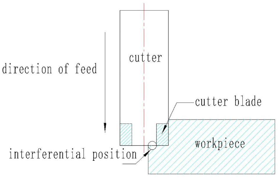
Schematic diagram of interferential phenomenon Non-interferential tool position.
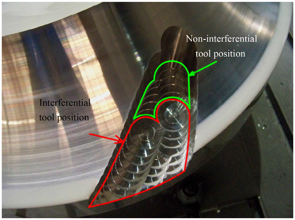
Interferential tool position and non-interferential tool position.
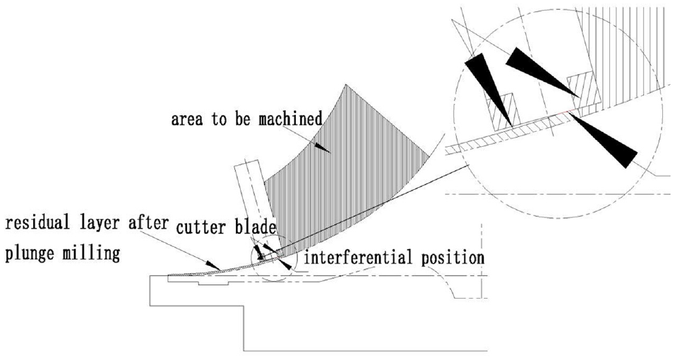
Interferential phenomenon for impeller plunge milling.
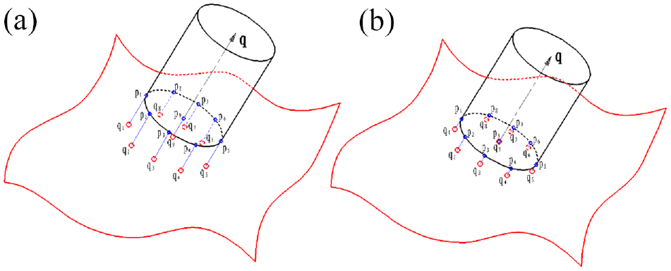
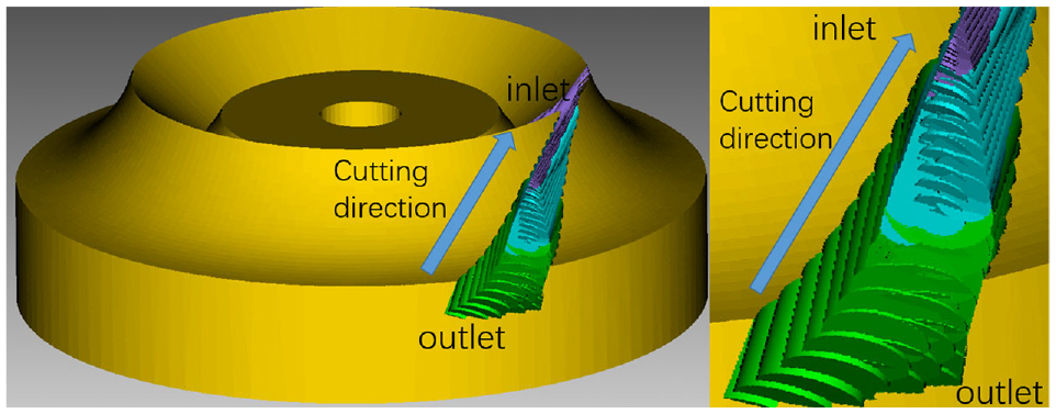
Obviously, the most direct method for avoiding interference is to adjust the cutter-axis vector which can be verified by a cutting simulation. Before adjusting the cutter-axis vector, as shown in Figure 4(a) to (c), it is clear that sections of the tool bottom are in contact with the hub surface residual layer, left by the first tool position at the end of the second cutter location, and the same phenomenon occurs at the third cutter location, undoubtedly causing interference. The cutter-axis vector of the second tool position is then adjusted to tilt 0.5° towards the cutter-axis vector of the third tool position, and the cutter-axis vector of the third tool position is adjusted to tilt 1° towards the cutter-axis vector of the fourth tool position, as shown in Figure 5. Obviously, the latter cutter positions effectively avoid the hub surface residual layer, and interference will not occur, as shown in Figure 4(d) to (f), but a rational inclination angle must be decided discreetly. If the tilt angle is too small, the residual hub layer left by the previous tool position cannot be avoided, and if the tilt angle is too large, the residual hub layer will be excessively large, which may affect the overall tool position planning and subsequent finish machining of the hub surface.
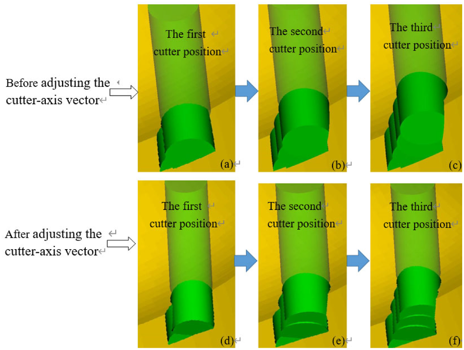
Cutter positions before and after adjusting the cutter-axis vector: (a) The first cutter position before adjusting the cutter-axis vector, (b) The second cutter position before adjusting the cutter-axis vector, (c) The third cutter position before adjusting the cutter-axis vector, (d) The first cutter position after adjusting the cutter-axis vector, (e) The second cutter position after adjusting the cutter-axis vector, and (f) The third cutter position after adjusting the cutter-axis vector.
Schematic diagram of the tilted direction of the cutter-axis vector.
Interferential tool position correcting algorithms
Step inspection
As shown in Figure 6, with regards to fixed-axis rough plunge milling, if S > w, whereby the gap between the cutter axis of two cutter positions exceeds the radial width of the cutting edge, then interferential phenomenon is highly likely to occur. Similarly, before optimising the cutter axis vector of variable-axis rough plunge milling cutter positions, it must be ensured that the rough plunge milling step is shorter than the radial width of the cutting edge. If the cutting edge crosses the centre of the bottom of the milling cutter, then the rough plunge milling step must be shorter than the radius of the cutter. With regards to the variable-axis rough plunge milling cutter position which needs to be optimised, the steps of all neighbouring cutter positions must be checked. If the step exceeds the cutter radius, an isoparametric method can be adopted to add middle cutter positions between the two cutter positions until the requirements are met. This process is known as step inspection.
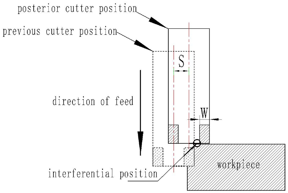
Schematic diagram of an interferential tool position due to step failure.
Tool axis vector optimisation
Provided that all cutter position steps meet the requirements, by combining with the above analysis, the tool axis vector optimisation can be summarised as follows: The angle between the normal workpiece surface vector at the cutter contact point and the cutter-axis vector of the adjacent tool position must increase gradually from outlet to inlet. The specific method is as follows:
① The cutter centre point for the tool position in centrifugal 3D impeller variable axis rough plunge milling, and the corresponding shroud surface data points calculated by an isoparametric method are extracted as shown in Figure 7. Only a set of tool positions close to the suction surface of the blade is listed in the figure. Two NURBS curves are fitted by cutter centre points Mi (i == 1, 2, 3, …, n) and the corresponding shroud surface data points Wi (i = 1, 2, 3, …, n) respectively, as shown in Figure 8.
② Perform discrete processing for the NURBS curves. The smaller the walking distance, the smaller the cutter-axis vector adjusting angle to avoid interference. According to previous studies, it is advisable to set the walking distance as 10−5 to obtain some discrete points, as shown in Figure 9.
③ Establish the cutter axis vector optimisation model as shown in Figure 10. The feeding direction is from the outlet to the inlet. The tool position of the variable axis plunge milling for each impeller channel is the m set. Take the tool position set of variable axis plunge milling near the suction surface of the impeller, and assume that there are f tool positions in this set. Then set the angle between the normal vector of the workpiece surface at the cutter contact point, and the cutter axis vector as α i (i = 1, 2, 3, …, f) as shown in Figure 11(a). Subsequently, set the intersection point of the cutter axis and the corresponding isoparametric line in the shroud surface as Wi (i = 1, 2, 3, …, f) as shown in Figure 11(b). After optimisation begins, the first tool position remains unchanged, calculating α2 and α1 for a comparison. If α2 > α1 is not satisfied, starting from W2, search for the discrete point sequence successively to the impeller inlet direction until a discrete point satisfying α2 > α1 is obtained. This discrete point is updated as point W2, and so on. Update the Wi (i = 1, 2, 3, …, f) point sequence, and consequently, α n >αn–1……α2 > α1. According to the cutter centre point sequence Mi (i = 1, 2, 3, … f), and the intersection point sequence of the cutter axis and corresponding isoparametric line in the shroud surface Wi (i = 1, 2, 3, … f), a new tool position sequence can be obtained through one-to-one calculations, and the interferential phenomenon will not occur in this set of tool positions, and so on, until all tool position sets are calculated.
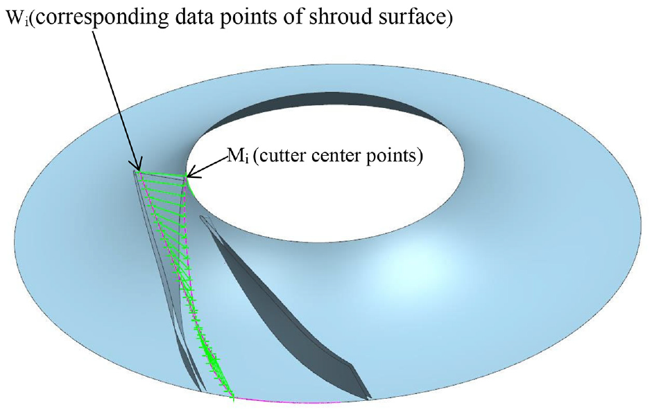
A series of cutter centre points and the corresponding shroud surface data points extracted.
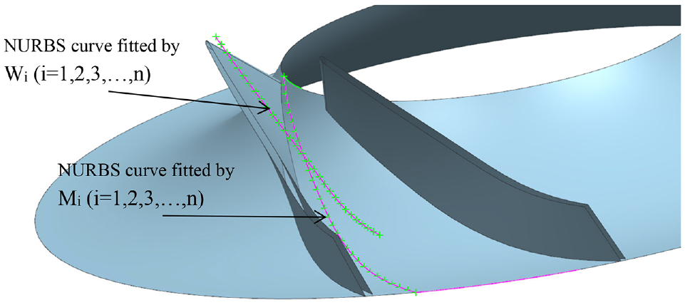
Fitted NURBS curves.
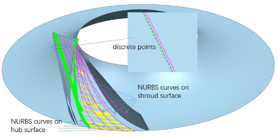
Some discrete points obtained through discrete processing of NURBS curves.
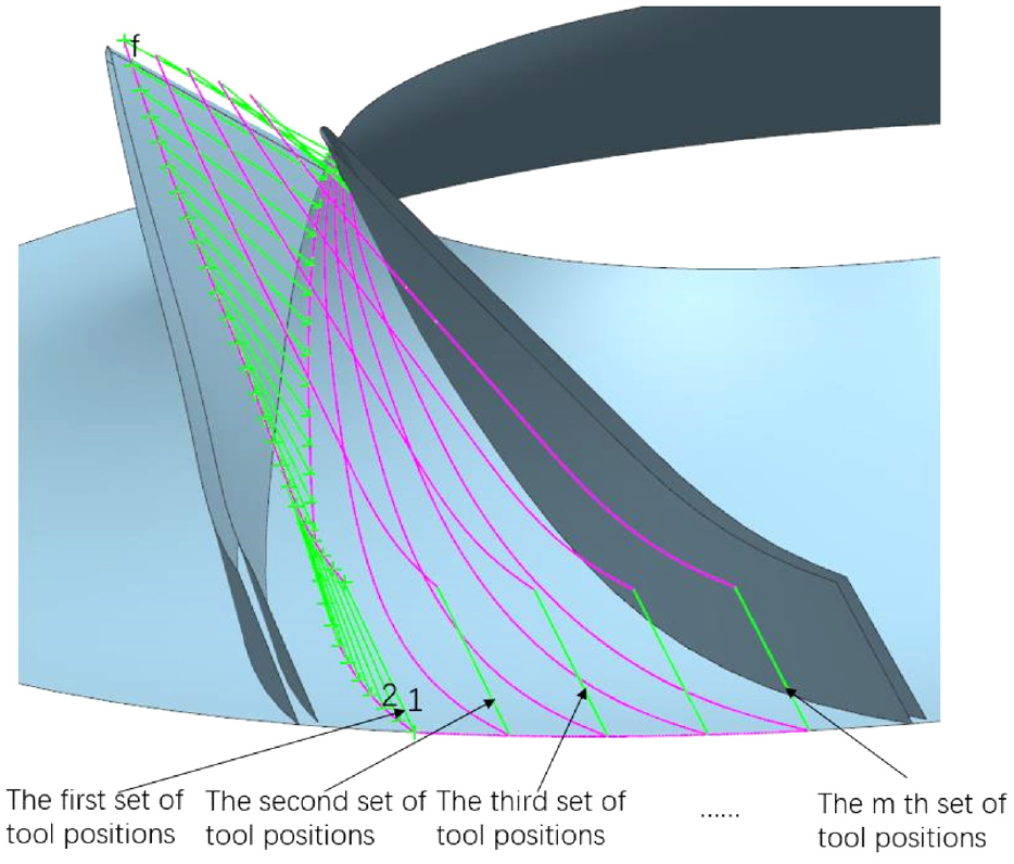
Cutter positions sequence.
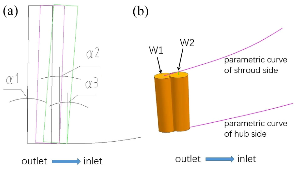
Schematic diagram of cutter axis vector optimisation: (a) Schematic diagram of cutter axis vector optimisation in cutter’s axial cross-section drawn, and (b) Schematic diagram of cutter axis vector optimisation in cutter’s three-dimensional diagram.
Determination of the slotting depth and the safety cutter height
The tool positions after optimisation cannot be used directly in the plunge milling of the impeller channel. Due to the fact that the cutter axis vectors are changed, hub surface overcutting might occur in some tool positions, as shown in Figure 12. The working allowance left for hub surface finish milling will be very small, even without any overcutting, which will affect the quality of the hub surface after hub surface finish milling. Likewise, a variation of the cutter axis vector will make the safety height less than the pre-set value, which will bring security risks when processing. Consequently, both the slotting depth and the cutter safety height need to be recalculated.
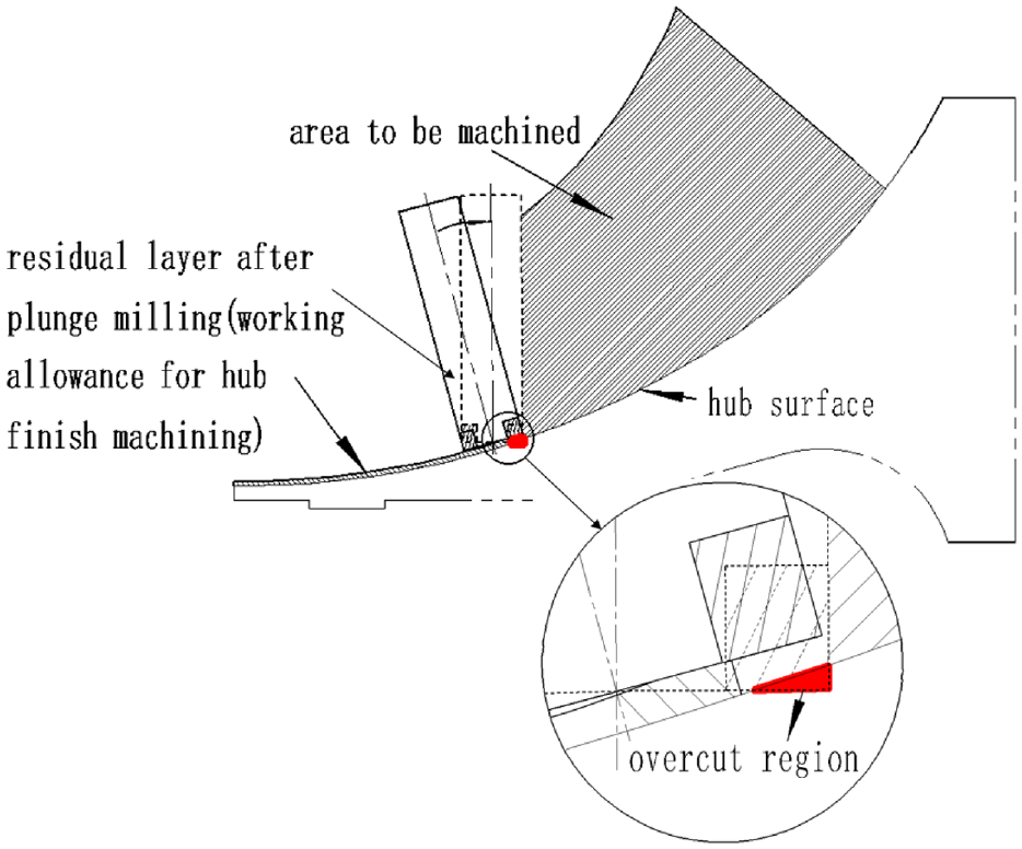
Overcutting at the hub surface.
The hub surface of the impeller Yintersection line of the suction surface and hub surface) rotating around the rotary axis Z. The vector equation is as follows:

Where
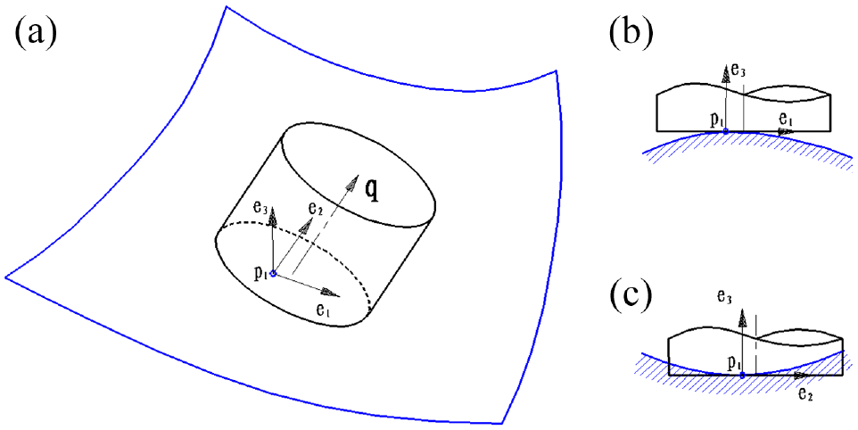
After determining the plunge milling cutter axial position, make the milling cutter move along the optimised direction of the cutter axis until the bottom plane of the milling cutter is in contact with the hub, or shroud surface, without interference. If the hub and shroud surfaces are arbitrary free surfaces, the bottom plane of the milling cutter can be discretised to determine the axial position of the cutter. As shown in Figure 13(b), after the projection point qi of each discrete point pi on the hub surface along the direction of the cutter axis is calculated, the axial position of the cutter can be determined from the minimum distance between corresponding points such as p7q7, as shown in Figure 13(a).
Determination of the cutter’s axial position in plunge milling of an arbitrary free-form surface: (a) Relative location of the cutter and arbitrary free-form surface before optimization, and (b) Relative location of the cutter and arbitrary free-form surface after optimization..
Considering that the hub and shroud surfaces of the impeller are rotative surfaces composed of hyperbolic points, calculating the projection points of multiple discrete points on the milling cutter’s bottom plane, on the surface to be processed, is highly time-consuming. If the projection of the cutter bottom plane on the hub surface does not exceed the hub surface boundary, the free contact point between the cutter bottom plane and the hub or shroud surface must be on the maximum excircle of the cutter bottom plane, meaning the cutter axial position can be obtained more efficiently. Here is a counter example to prove the correctness of this conclusion. It is assumed that the interference free contact point between the milling cutter bottom surface and the hub surface occurs at point p1 within the maximum excircle, as shown in Figure 14(a). Two normal sections would need to be made along the main direction of the impeller hub surface over point p1 as shown in Figure 14(b) and (c), respectively. Figure 14(b) shows the interference free contact point p1 between the cutter bottom plane and the hub surface is within the maximum excircle. Since both the hub and shroud surfaces are composed of hyperbolic points, the bottom plane must interfere with the hub surface or the shroud surface, as shown in Figure 14(c). Therefore, the hypothesis is disproven. That is, the free contact point between the milling cutter bottom plane and the hub or shroud surface must occur on the maximum excircle of the bottom plane of the cutter.
Interference-free CC point between the flat end of plunge milling cutter and hyperboloid: (a) Relative location of the plunge milling cutter and hyperboloid, (b) Interference-free CC point between the flat end of plunge milling cutter and convex hyperboloid, and (c) Interference-free CC point between the flat end of plunge milling cutter and concave hyperboloid.
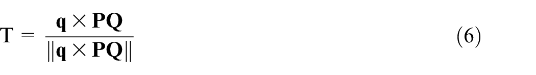
To determine the interference free contact point between the bottom plane of the cutter and the hub surface, and considering that the contact point occurs on the maximum excircle c on the bottom surface of the cutter, it is necessary to ensure that the bottom circle c and the hub surface not only contact at the cutter contact point, but are also at a tangent. This ensures that there is no local interference between the bottom surface of the tool and the hub surface at the cutter contact point. As shown in Figure 15, the cutter contact point Q is found using the following two formulas:


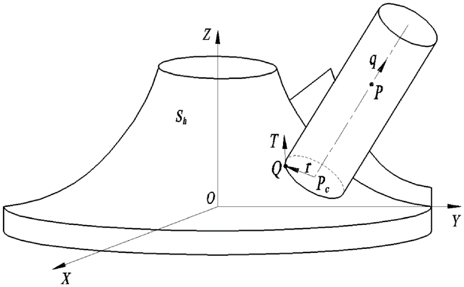
Determination of the cutter axial position in plunge milling hub surface.
where P is a given point on the cutter axis;
As vector
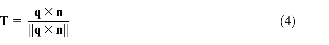

Formula (4) is invalid if
where
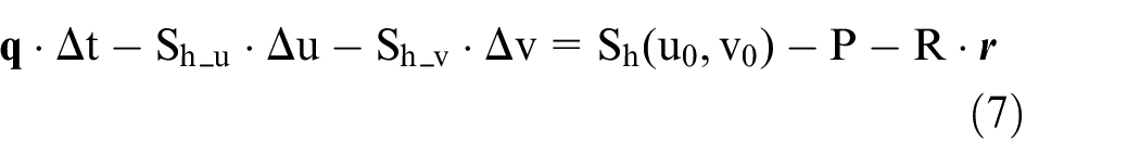
where
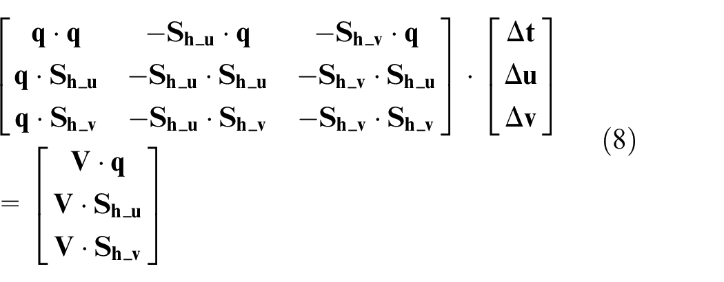
Through solving the formulas,

The same method is used to calculate the tangent point between the tool bottom plane and the impeller shroud surface. The cutter safe lifting height for plunge milling can then be determined along with the appropriate safety distance. If there is cutter tip fillet, the hub surface needs to be offset along its normal direction to the tool tip fillet radius. The process for determining the cutter axial position is similar to above.
After the axial positions of the cutter positions are updated, a subsequent step inspection is required. If middle cutter positions are added, the cutter axial vector optimisation and axial position determination must be conducted again in order several times until the process ends. A flow chart of this process is shown in Figure 16.
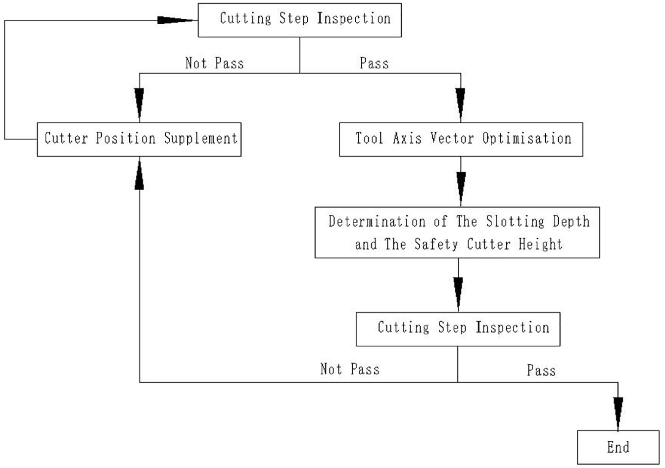
Algorithm flow chart.
Numerical examples
Centrifugal 3D impellers are divided into three types, closed, semi-open and open, amongst which, an open impeller is usually called a blisk. As a blisk has no shroud or hub disk, the interferential phenomenon discussed in this paper does not exist. Closed impellers are classified into whole milling and two-piece welding impellers due to their different processing methods. In whole milling impeller processing, feeding can only be done from the inlet and the outlet due to the constraints of the shroud disk, and is therefore not suitable for plunge milling. Without the shroud disk constraints, two-piece welding and semi-open impellers are more suitable for the optimisation algorithm proposed in this paper. With two-piece welding closed impellers, blades and hub disks are produced from a blank, and the method has no obvious differences from semi-open impellers, before it is welded together with the shroud disk. Plunge milling is more suitable for large size impellers and impellers with not severely twisted blades. Plunge milling cutters used for small impellers are also small and flexible, therefore side milling is more appropriate than plunge milling for rough machining small impellers. In addition, side milling is generally more appropriate for impellers with very twisted blades, as they are difficult to feed owing to the narrow and twisted channels used in plunge milling. For large sized impellers, particularly when the impeller diameter is greater than 1 m, plunge milling is the most suitable method. The advantages are easy tool path planning and a high processing efficiency. Although impellers with a diameter of 500–800 mm are also suitable for plunge milling, difficulty in tool path planning limits the CNC programmer’s work. Consequently, it is the primary target of the optimisation algorithm proposed in this paper.
A centrifugal semi-open 3D impeller is given as a simulation example, with the following major parameters; impeller diameter 532mm; blade number 17; width of the narrowest position of the channel 12.5 mm; blade outlet height 32 mm. These parameters are representative and typical of a primary target for the optimisation algorithm presented in this paper.
The channel is divided into three sections to simplify the rough machining of variable axis plunge milling. The cutting direction is from the outlet to the inlet. For the outlet section, use a ∅30 flat bottom plunge milling cutter, a ∅16 one for the middle section, and a ∅8 for the inlet section. The simulation results before optimisation are shown in Figure 17. Clearly, the overall hub surface residual layer presents a down-step trend, indicating that at each stage, before the feed for plunge milling near the hub, parts of the tool bottom other than the main cutting blade are in contact with the hub surface residual layer left by the previous tool position, therefore interference occurs.
Cutting simulation results before optimisation.
Figure 16 shows the tool position optimisation cycles through three main algorithms. The first one being the cutting step checking, the second one being the cutter axis vector optimisation algorithm, and the third being an update in the slotting depth and cutter safety height. Optimisations were carried out for all three sections of plunge milling tool position. When the tool, cutting parameters, and cutting direction were unchanged, the post-optimisation simulation results were as shown in Figure 18. It can be seen that the overall residual layer on the hub surface shows an up-step trend after optimisation, and thus, every time the plunge milling feeds near the hub, the residual layer left by the cutter location may be avoided, and the interferential phenomenon will not occur.
Cutting simulation results after optimisation.
The magnified image of the cutting stage near the outlet before cutter axis vector optimisation is shown in Figure 19. In the first cutting row, parts of the tool bottom of the second cutter position were in contact with the residual layer on the hub surface left by the first tool position. Likewise, parts of the tool bottom at the third cutter position were in contact with the residual layer on the hub surface left by the second tool position, and so on. The same thing occurs in every cutting row. The enlarged drawing of the same cutting stage after cutter axis vector optimisation is shown in Figure 20. No part of the tool bottom of the posterior cutter position encountered the residual layer on the hub surface left by the previous tool position, and so interference was eliminated.
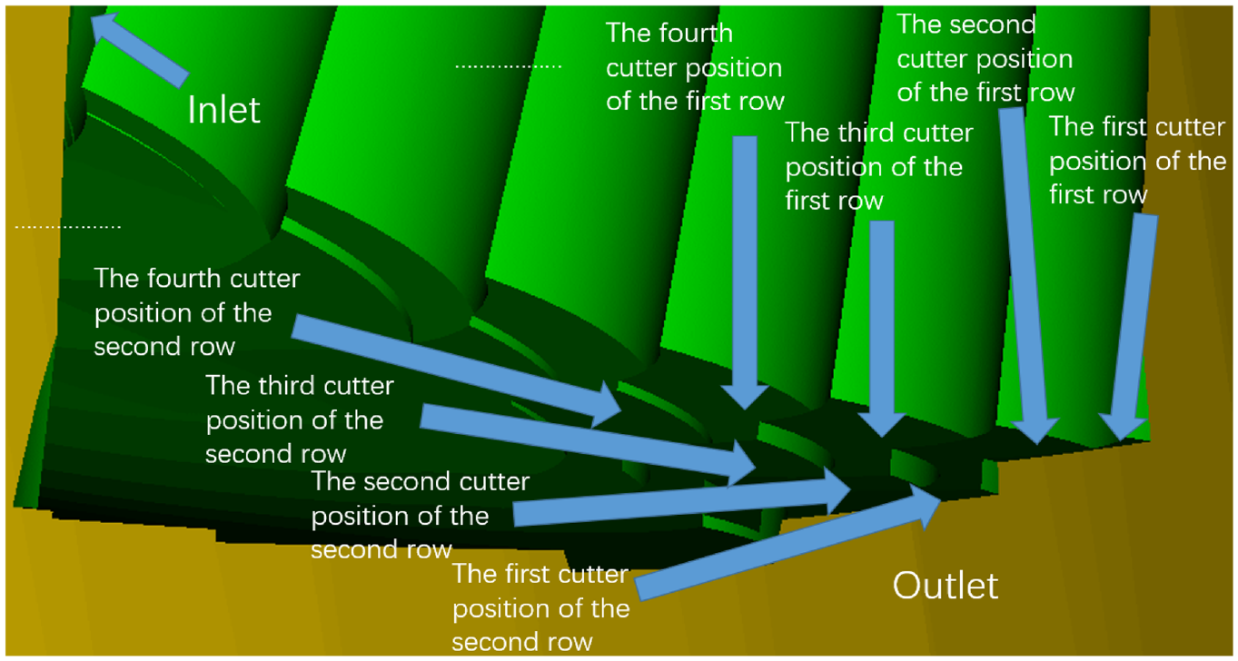
The enlarged drawing of the cutting stage near the outlet before optimisation.
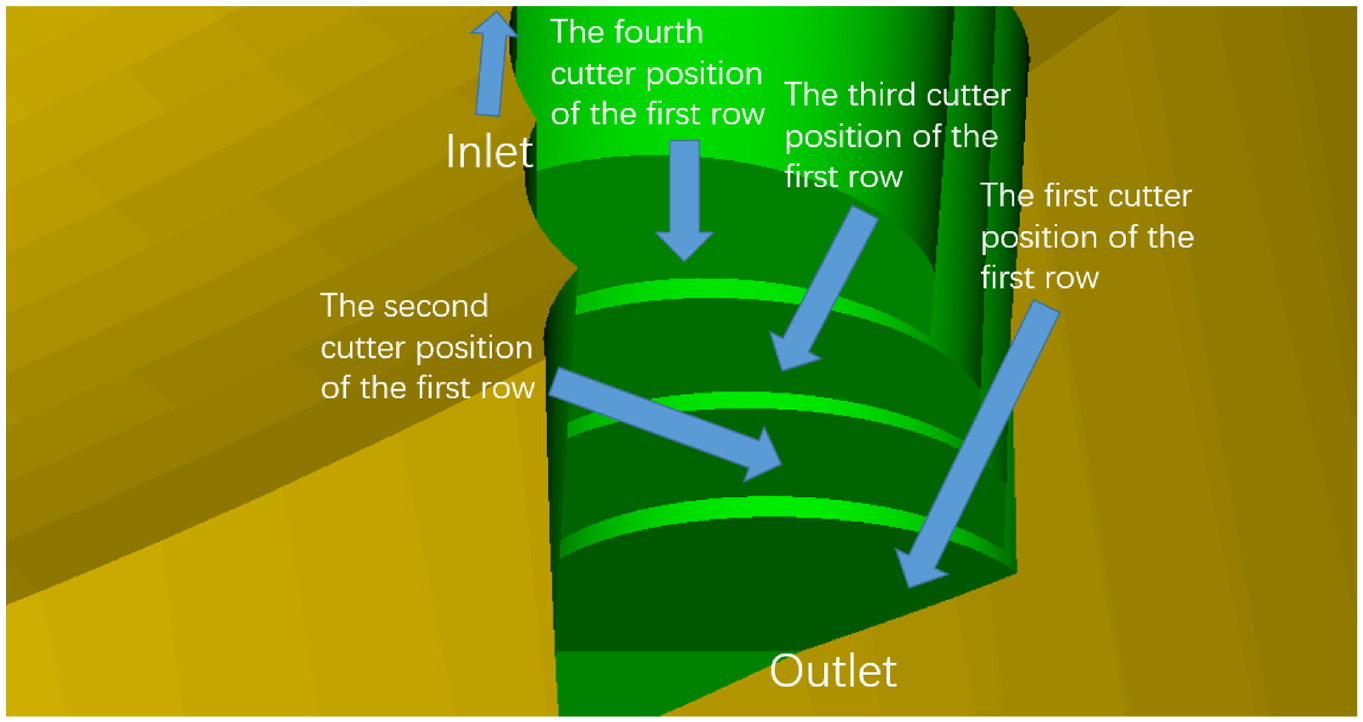
The enlarged drawing of the cutting stage near the outlet after optimisation.
The cutting simulation was redone with the work blank without the region under the hub surface, as shown in Figure 21. In view of the three cutting sections’ simulation, the material was not cut through, meaning that overcutting at the hub surface did not occur and the updated slotting depth was correct. By observing the cutting simulation process, the work blank was not scraped by the cutter tip at the first stage of each plunge milling feed, which means the updated cutter safety height was also correct.
Cutting simulation with the work blank without the region under the hub surface.
Summary
In slot plunge milling of centrifugal 3D impellers, parts of the tool bottom are often in contact with the residual layer on the hub surface left by the previous tool position at the end phase of every cutter location, which causes interference. To solve this, cutting step inspection and cutter axis vector optimisation were performed for the variable axis plunge milling tool position. In cutter axis vector optimisation, the angle between the normal vector for the workpiece surface at the cutter contact point, and the cutter-axis vector of the adjacent tool position slightly increased in a gradual manner from the outlet to the inlet. After optimisation, in order to avoid overcutting at the hub surface, sufficient and even working allowance must be left for the subsequent hub surface finish milling, and the safety height must be retained at a rational scale. An iterative algorithm for the tool centre position and cutter safety height was provided. In the numerical simulation, a typical 532 mm diameter impeller was adopted, and a three-step optimisation was conducted on the three sections of the plunge milling tool positions. The simulation results show that the interference was eliminated, and the slotting depth and cutter safety height were also correct.
Footnotes
Appendix
Authors’ contributions
Improve processing efficiency and machining precision of centrifugal 3D impeller
Declaration of conflicting interests
The author(s) declared no potential conflicts of interest with respect to the research, authorship, and/or publication of this article.
Funding
The author(s) disclosed receipt of the following financial support for the research, authorship, and/or publication of this article: The research was supported by National Natural Science Foundation of China (no. 12002198).
Ethics approval
Not applicable
Consent to participate
Yes
Consent for publication
Yes