
Abstract
The machining of porous materials is commonly accompanied with high and irregular cutting forces, high cutting temperature, poor surface integrity, and severe tool wear. The porous materials are considered difficult to be machined. Porosity reduces the rate of heat transfer; moreover, it impairs the continuous cutting and therefore leads to cyclic loads. The main objective of the present study is to investigate the influence of superimposing ultrasonic vibration to the cutting motion of the cutting tool on the surface integrity of the porous materials. For this purpose, the mechanism of chip removal in vibration assisted machining of porous materials was analyzed and porous stainless steel 316L specimens were machined by ultrasonic vibration assisted turning. It was illustrated by the porosimetry of the machined surfaces that the surfaces machined by conventional turning had higher rate of surface porosity compared with ultrasonic vibration assisted turning. In the latter process, the SEM images of the machined surfaces manifested the existence of a kind of rubbing mechanism and material overlaps, which was attributable to the friction existing between the cutting tool with micro scale reciprocating motion and the surface of the workpiece. The overall impact of imposing ultrasonic vibration to the cutting tool motion in the cutting direction was the achievement of a trade-off between preserving the porosity and improvement of the surface quality. This effect was bolstered by increasing the vibration amplitude.
Keywords
Introduction
In recent years, the use of porous materials has been growing rapidly not only in the medical industry but also in many other industries. A wide range of base materials can be used in porous structures. For example, porous carbon has been used as an air bearing and porous silicon in Li-ion batteries and solar cells. The porous titanium is a suitable material for orthopedic and dental applications due to its excellent biocompatibility.1,2
Recently, the use of porous Nitinol has been considered as a bone substitute.3–5 Stainless steel (type 316 low carbon) is another common material for implants. Porous stainless steel is widely used for biomedical materials due to its high strength-to-weight ratio and excellent corrosion resistance. 6 The austenitic stainless steels are often used in medical applications such as orthopedic implants due to their properties such as corrosion resistance, high fatigue and high fracture resistance. However, the main problem with orthopedic metal implants is the Young’s modulus mismatch between non-porous metal and bone. 7 Although open-pore metals are preferred for implant use due to bone growth facilitation, closed-pore metals may be used in orthopedic load-bearing implants. 7
The porous metals can be produced by different processes such as sintering and powder metallurgy, metal deposition on polymer foams, and anodizing. These materials are made by near-net shaping and only require a light machining for improved surface quality and dimensional accuracy. The two important factors of nominal porosity and pore size must be controlled during the manufacturing processes to make the porous material suitable for their applications. Porosity is the ratio of the total cavity volume to the apparent volume of the material. The size of the pore is also expressed based on the average diameter of the cavities. However, there are some difficulties in the use of porous materials. The pressed and sintered powder metallurgy alloys are difficult to machine due to the presence of porosity. The porosity not only causes a low heat transfer rate, but also leads to discontinuous cutting, thus imposing a cyclic load on the tool tip.6,8 In order to control the influence of the surface porosity on the machinability, the mechanism of cutting the porous materials should be analyzed. This has not been given sufficient consideration except for very limited cases, mainly on micro scales. It should be noted that the porous workpieces undergo structural changes during machining. The selection of the best machining method is, therefore, a challenge to apply positive control on the workpiece’s structural changes. New manufacturing technologies and hybrid machining methods are expected to meet these requirements.
Zurecki et al. 9 performed two examinations for turning of powder metallurgy (PM) steel using cryogenic cooling. They used 7.7% porosity (high density) and 14.5% (low density) porosity of PM steel in sintered and hardened states. They reported that the filling of pores reduced for both high and low density PM steels. The surface density of the hardened workpiece was also reduced due to the presence of a white layer. It should be noted that the surface porosity is not desirable for some applications of PM steels. Many applications for machined PM steel pieces require high geometric accuracy and low surface roughness to reduce wear on the workpiece and ensure proper alignment with the other workpiece. 10 Therefore, surface density (e.g. lack of surface porosity) is desirable to increase the strength of machined parts, especially the surface layer. 11 Surface compaction is also associated with an increase in residual compressive stress that can improve the fatigue strength of machined workpieces. 9 The term pore filling in these cases is used to describe the irregular plowed surfaces. Tutunea-Fatan et al. 12 and Fakhri et al. 13 have shown that in micro processing of porous titanium foams (54% porosity), the large size of the pores in the workpiece (0.5–1.5 mm) and the small size of the cutting tool (less than 1 mm diameter) lead to discontinuity in the cutting process. The fine folds created in the material result in filling of the surface pores. For the large pores compared to the radius of the cutting tool edge, the materials at the edge of the pores are not removed by cutting but are driven into the pore cavities. Heidari and Yan 14 observed that the morphology of the chip and the topography of the surface depended on the pore size and the undeformed chip thickness. The majority of the smaller pores were closed during machining due to the welding phenomenon. This resulted in an average reduction of the pores from 30% to 1%. The large pores changed to holes on the machined surfaces. Qiao et al. 15 conducted experimental studies on the shear angle in machining of powder alloy parts of super alloys. The results of their studies illustrated the relationship that could exist between the shear flow stress, shear strain and strain velocity in high-speed machining. They also found that the cutting speed had a significant effect on the shear angle and shear strain. Sun et al. 16 studied the model of wear mechanism and shear band formation, using powder metallurgy material of Ti-6Al-4V titanium alloy prepared using hot isostatic pressing (HIP) technology. They observed variation of the cutting force in the machining of the powder metallurgy material that confirmed the drift of the shear band due to the micro-pore. It means that the cutting band in powder metallurgy machining is not a straight line/plane. They found that the presence of micro-pores in the shear band could improve the concentration of local thermal softening or plasticity instability. This phenomenon was also reported by other researchers.17,18 Yang et al. 19 investigated the mechanism of orthogonal machining of green powder metallurgy parts (before final hardening. Their results show that the surface roughness of the machining surface decreases with increasing the undeformed chip thickness and radius of the cutting edge of tool and it increases slightly with increasing the rake angle. These results are in contrast with the traditional notion of machined surface roughness. They introduced three types of peeled off, shear deformation, and plowing mechanisms for material removal.
The advantages of superimposing ultrasonic vibration to the cutting and feed motion in the machining processes have vastly been investigated. Babitsky et al. 20 and Suzuki et al. 21 reported that adding ultrasonic vibration reduces the length of the adhesive contact on the rack surface of the tool, which reduces or eliminates the build-up-edge. Also many researchers (e.g. Xu et al., 22 Jamshidi and Nategh, 23 Lotfi et al. 24 ) have reported that the addition of ultrasonic vibration reduces the cutting force. This leads to a reduction in the tool wear25–27. The vibration assisted machining is a discontinuous cutting process. In a discontinuous process, the workpiece cools during separation between the tool and the cutting area. This adds to the advantage of decreased tool wear in vibration assisted machining. Some researchers28,29 have reported that by adding ultrasonic vibration to the tool, the depth of the hardened surface layer on the surface of the workpiece in vibration turning would be about half of traditional turning and its hardness is close to the base metal. This can be due to the reduction of the radial force component and the thermal behavior and chip formation mechanism, which are different in the conventional turning and ultrasonic vibration assisted turning.
As already mentioned, the porous materials are considered difficult to be machined. Considering the advantages of adding ultrasonic vibration to the cutting tool, it can be expected that vibration assisted turning can be an appropriate candidate to help overcome the machining difficulties of the porous materials. Recently, the results of a study have been published on the ultrasonic vibration assisted drilling of powder metallurgy parts. 30 The authors reported that the depth of the compacted layer reduced by about 40%, together with the reduction of the tool wear. To the best knowledge of the present authors, no other report is available on the application of ultrasonic vibration assisted turning of porous materials. In the present study, the material removal mechanism and surface integrity in ultrasonic vibration assisted turning of porous stainless steel 316L have been experimentally investigated. For this purpose, the porosities of the specimens were first examined by mercury intrusion porosimetry and scanning electron microscope (SEM) images. Subsequently, the specimens were machined by the traditional and vibration assisted processes. The cutting forces, the surface porosities of the specimens and the microstructure of machined surfaces were then compared.
Material and methods
Measurement of the porosity
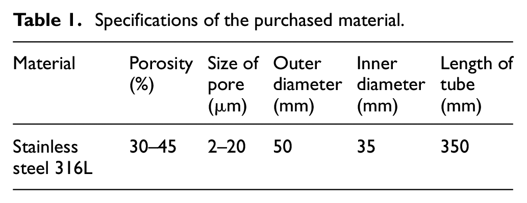
For the experiment, a cylindrical porous stainless steel 316L was used. The diameter of the specimen was 50 mm, and its length was 350 mm. The composition of alloying elements and its properties are given in Table 1.
Specifications of the purchased material.
Two methods were used to measure the size of porosity, SEM images and mercury porosimeter. For this purpose, first several SEM images (six images) were prepared from different regions of the sample and measurements were made several times for each of them. As a result, the mean and standard deviation of the porosity size were obtained. Image-J software was used to measure the size of the pores.
To prepare the SEM images of the surface of the workpiece before machining, electrification was implemented by using conductive aluminum adhesive tape and subsequently by PVD method in COXEM machine made in South Korea (Figure 1).
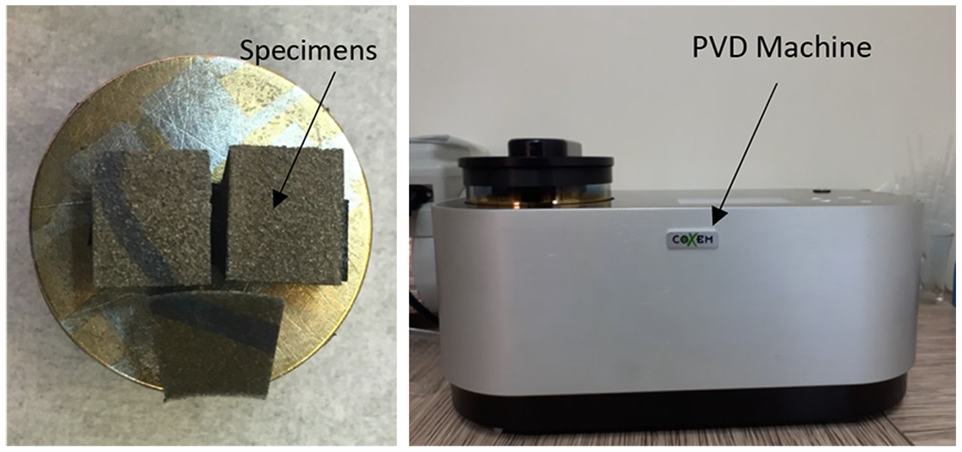
COXEM device for surface conditioning of samples (right) specimens after golden coating (left).
A sample of the images of the specimen produced by the scanning electron microscope in different magnifications is shown in Figure 2. To determine the percentage of porosity, the gray images were converted into binary ones by Image-J software. These images are a collection of dark and light spots. The ratio of the dark spots to the total surface is considered as an indicator of the percentage of porosity. This was performed on six SEM images, which were taken from a sample before machining, to determine the surface porosity and the results were as 40.966%, 39.368%, 42.154%, 41.623%, 44.802%, and 43.725%. The mean value is 42.106% and the variance is 3.7842%.
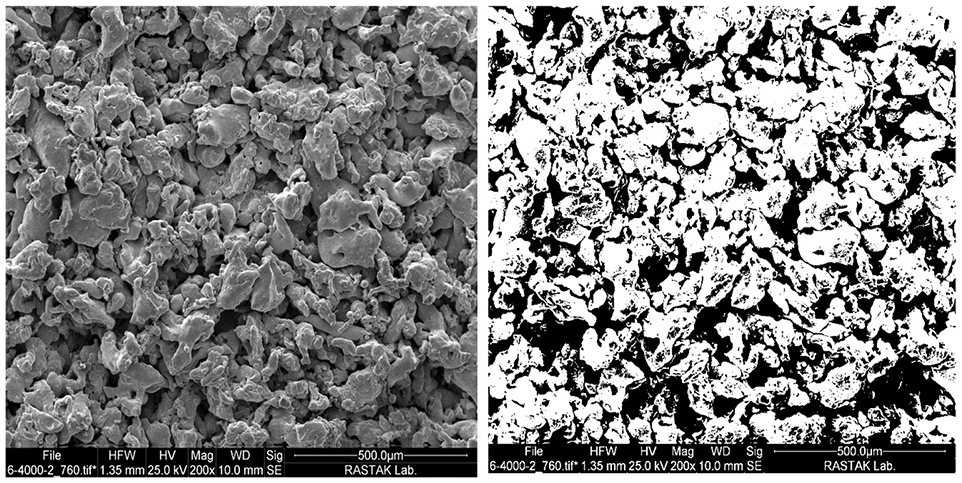
SEM image (left) and binary image (right) of the workpiece surface before turning; magnification 200.
In machining of porous material, size and distribution of pores are important. Because of it in the second method, low pressure mercury porosimetry was employed to investigate the size and distribution of porosity in the surface and volume of the material. The basis of this method is on a non-wetting fluid such as mercury so that this fluid enters the porous body with high pressure. Due to the high wetting angle of mercury, an external pressure is required to penetrate the pores. In this method, mercury penetrates into the pores in an autoclave with different pressure values. The pressure required is inversely proportional to the size of the pores, so for the larger sizes of the pores, the less pressure is required. The pressure sensors make it possible to determine the pressure drop in a porous body. These results are substituted in the Washburn equation, and the diameters of the pores can be calculated, as follows 31 :
where P is the mercury pressure (kPa); D, the pore diameter (μm); γ, the surface resistance of mercury, equal to 485 mN/m (485 dyne/cm); θ, the contact angle of mercury and sample (commonly 140°).
In this experiment, a PASCAL 140 mercury porosity device made by the Italy-based Thermo Finnigan Co. was used to measure pore sizes and their distribution (Figure 3). The PASCAL 140 is a low pressure porosity device for determining macro-pores. The measuring range of the pore radius is between 1.9 and 58 μm (up to 900 μm with super macro pores) and the pressure range for measurement is 0.01–400 kPa (4 bar). The pressure is applied through the PASCAL system with variable speed according to the pore size and the actual penetration rate of mercury.
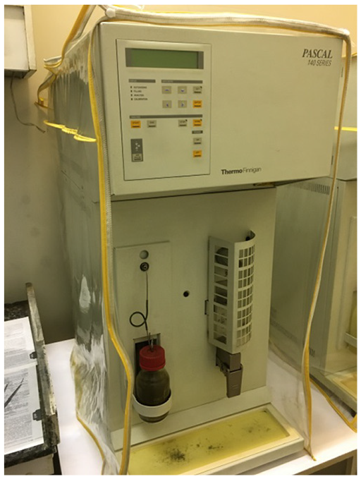
Mercury porosimeter.
Figure 4 shows the standard graph of the cumulative volume of mercury (left axis) in terms of the pore size (horizontal axis). When the mercury pressure is low, the larger pores are filled with mercury. With the increase of pressure, the mercury enters the smaller pores. The cumulative volume of mercury in smaller pores increases due to their larger surface area. The blue diagram shows the size of the pores and the volume percentage of the pores (right axis).
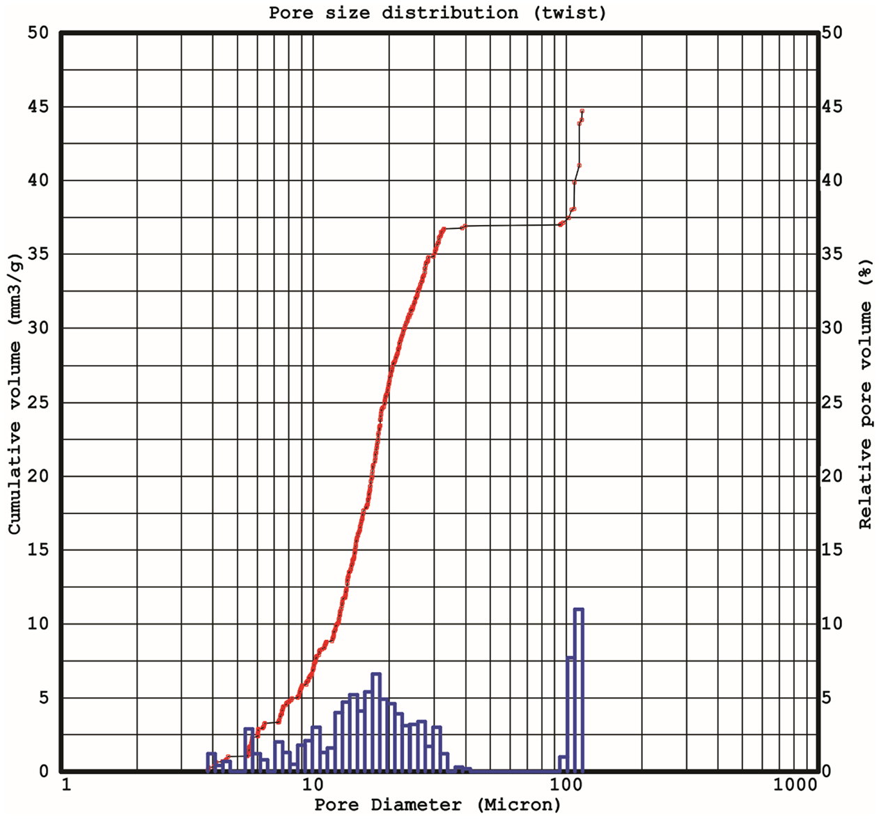
Pore size versus cumulative mercury volume.
As can be seen from Figure 4, pores with a diameter of 107.65 μm have the highest frequency. For the measured sample, about 15% of the pores are less than 10 μm in diameter, 65% are 10–30 μm in diameter, and 20% of are 95–110 μm in diameter.
Machining experiments
The setup of machining experiments is shown in Figure 5. In the machining experiments, a flatbed type CNC lathe model TME40 made by Tabriz Machine-Building Company equipped with Siemens802c control system has been employed. A dynamometer made by the Swiss company KISTLER, model BA 9257, was used to measure the machining forces. This dynamometer is able to measure forces dynamically and with 5 N resolution in all three coordinate directions.
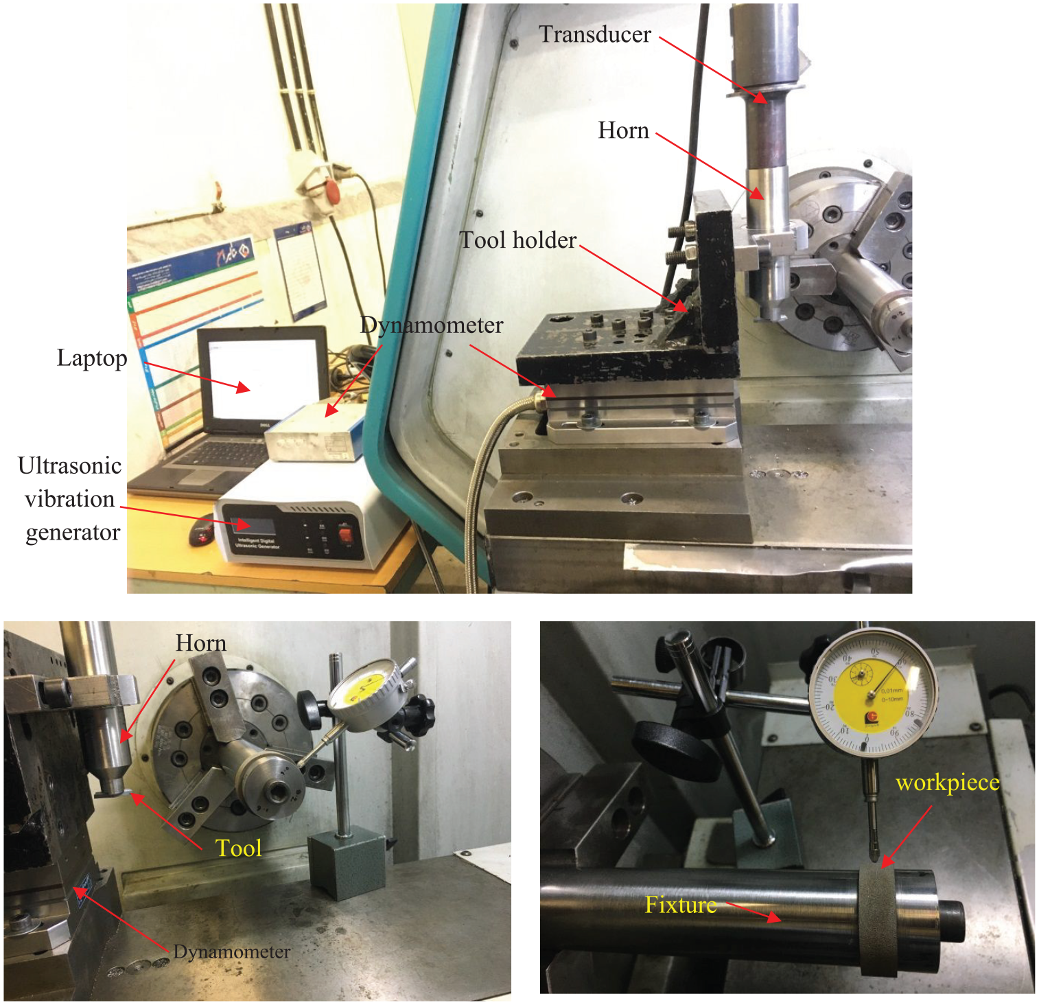
The setup of machining experiments.
All tests were performed by AH645 type tool with VBMT 160404-PS. The angles and the geometry of the cutting tool used were measured with the video/vision measuring machine (VMM) shown in Figure 6, the results of measuring which are shown in Table 2. VMM is non-contact type of measuring machines which use optics as source of inspection.
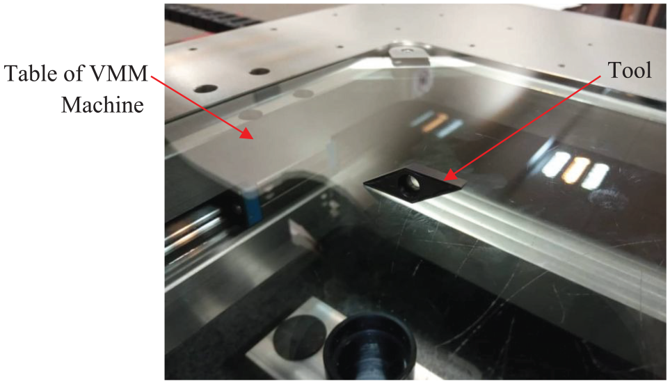
Turning tool in VMM machine.
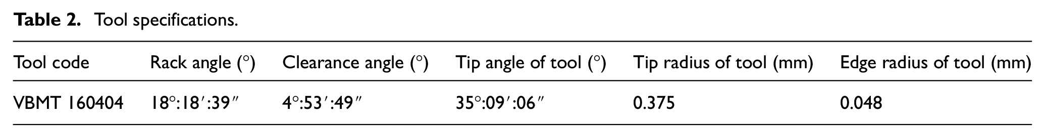
Tool specifications.
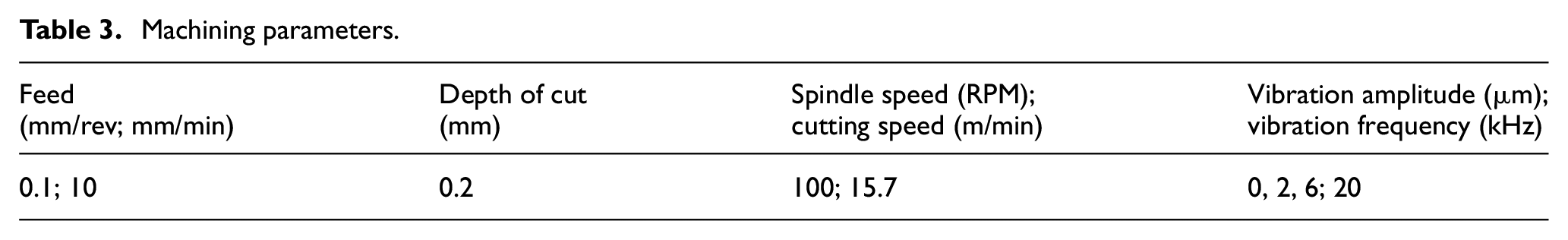
It is noteworthy that runout has an effect on the turning process and its results. The tip radius of the indicator is larger than the size of the surface porosities and has no negative effect on the runout measurement results. The total length of the workpiece held in the fixture in Figure 6 was divided into three equal parts. The first part was machined by traditional turning; the second part by ultrasonic assisted turning with a low-amplitude, near the critical speed (the speed at which the linear velocity of the vibrating tool was equal to the linear velocity of the rotating part; and the third part by ultrasonic assisted turning with a high-amplitude. The three turning operations were carried out at the same conditions: feed rate, 0.1 mm per revolution (10 mm/min): depth of cut, 0.2 mm; and the number of spindle rotation, 100 rpm (15.7 m/min). The machining and vibration parameters are summarized in Table 3. The cutting forces were measured in three directions: tangential (cutting), radial and feed. The forces were measured for porous stainless steel 316L.
Machining parameters.
Results and discussion
Since the sampling speed of a dynamometer (maximum 3 KHz) is several times slower than the frequency of ultrasonic vibrations (about 20 KHz), the dynamometer is not able to measure the actual instantaneous forces in each vibration cycle and the reported results are in fact the average of the cutting forces. The values of the forces obtained experimentally during the various stages of the experiments in terms of different vibration amplitudes, are shown in Figures 7 and 8.
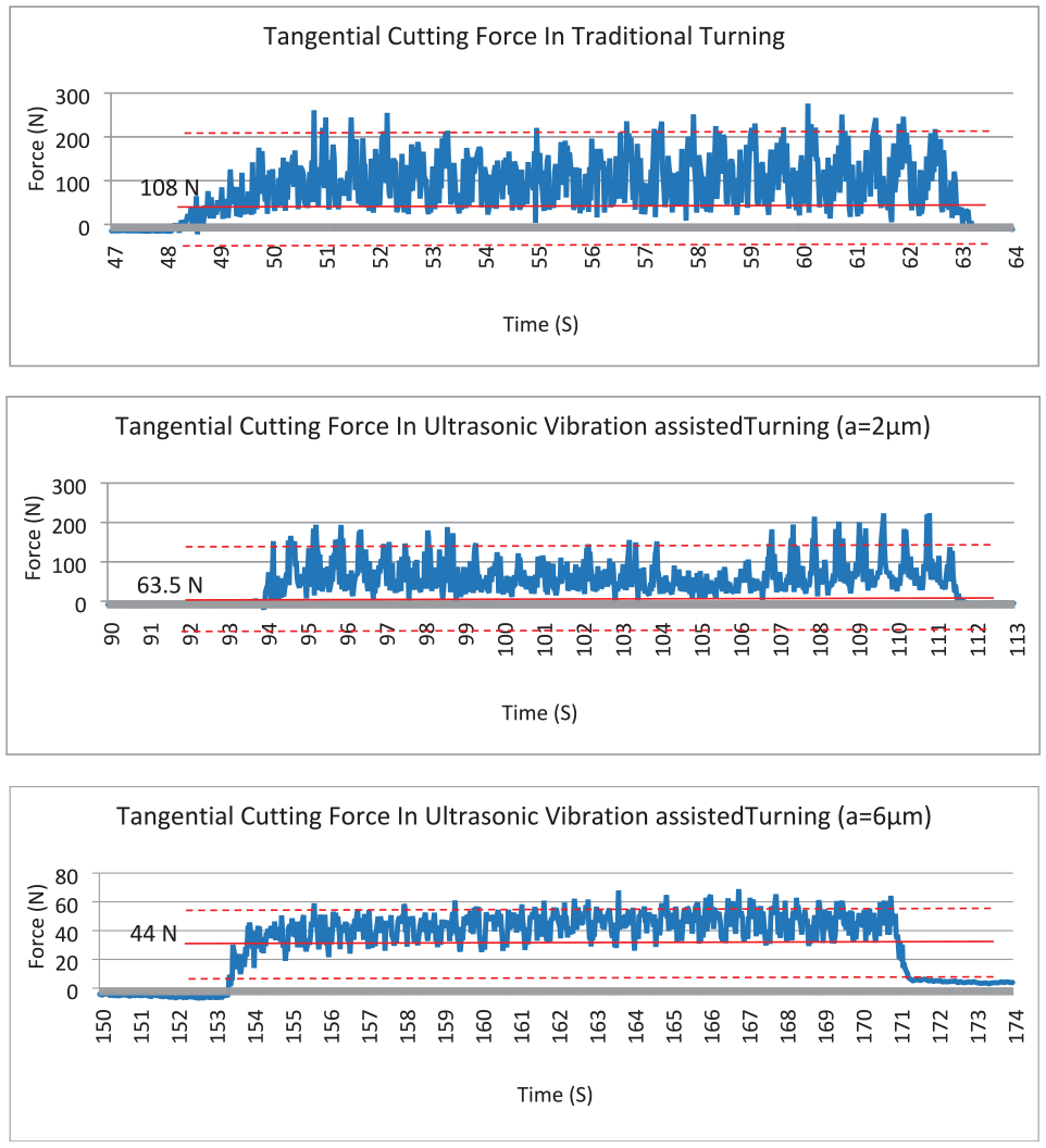
Cutting force in conventional and vibration-assisted turning with low (a = 2 µm) and high (a = 6 µm) amplitudes; frequency 20 kHz; cutting speed 15.7 m/min, depth of cut 0.2 mm, feed rate 10 mm/min.
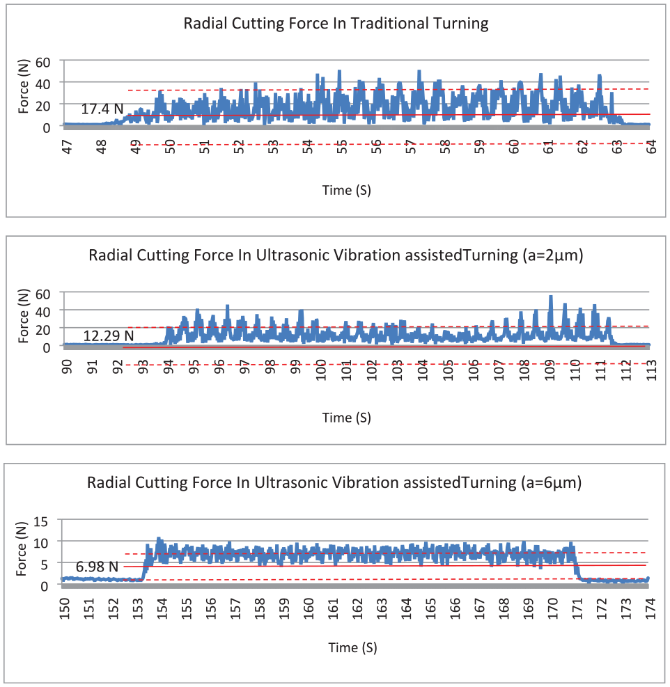
Radial force in conventional and vibration-assisted turning with low (a = 2 µm) and high (a = 6 μm) amplitudes; frequency 20 kHz; cutting speed 15.7 m/min, depth of cut 0.2 mm, feed rate 10 mm/min.
As shown in Figures 7 and 8, the cutting forces decreases with the addition of ultrasonic vibration. The average tangential and radial cutting forces were decreased about 30%–40% and 60%, respectively, by using low and high amplitudes of ultrasonic vibration, compared to the traditional turning. This result is consistent with the results of several researches already mentioned in Introduction.22–24 Increasing the vibration amplitude leads to a decrease in the average cutting force in vibration-assisted turning, which is due to the increase in tool separation time and cutting area in the ultrasonic vibration cycle.
The presence of fluctuations in the cutting forces during machining of porous materials is a common effect. This has been verified by several researchers (e.g. Abolghasemi Fakhri et al. 13 ). The decrease of the amplitudes of these fluctuations is an additional advantage of ultrasonic vibration assisted turning compared with the conventional process. This can be evidenced in Figures 7 and 8. The main reason for this is that in traditional turning of porous materials, the presence of pores causes intermittent break of the chip, which leads to fluctuations in the cutting forces. However, the addition of ultrasonic vibration to the cutting tool leads to lesser porosity-induced cutting discontinuity. This can be verified by the study of the morphology of the chips.
The morphology of chips produced in conventional and vibration assisted turning is shown in Figure 9. The conventional turning chips have short lengths and small curvatures (folds). Chips of high-amplitude vibration assisted turning are longer and almost straight. Chips of low-amplitude vibration turning are shorter in length and smaller in curvature compared with the higher amplitude.
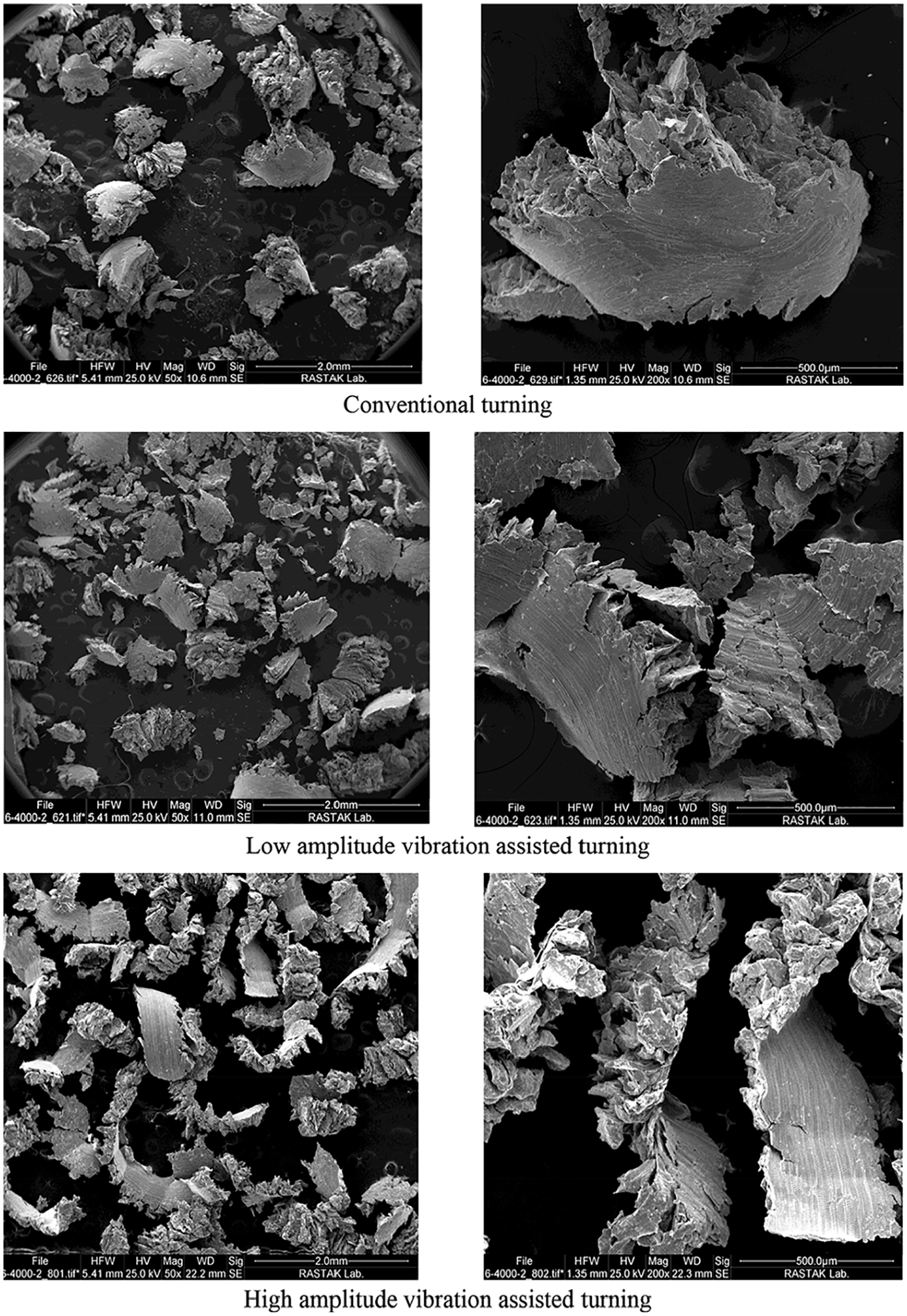
SEM images of chips in conventional and vibration assisted turning; magnification 50 (left) and 200 (right).
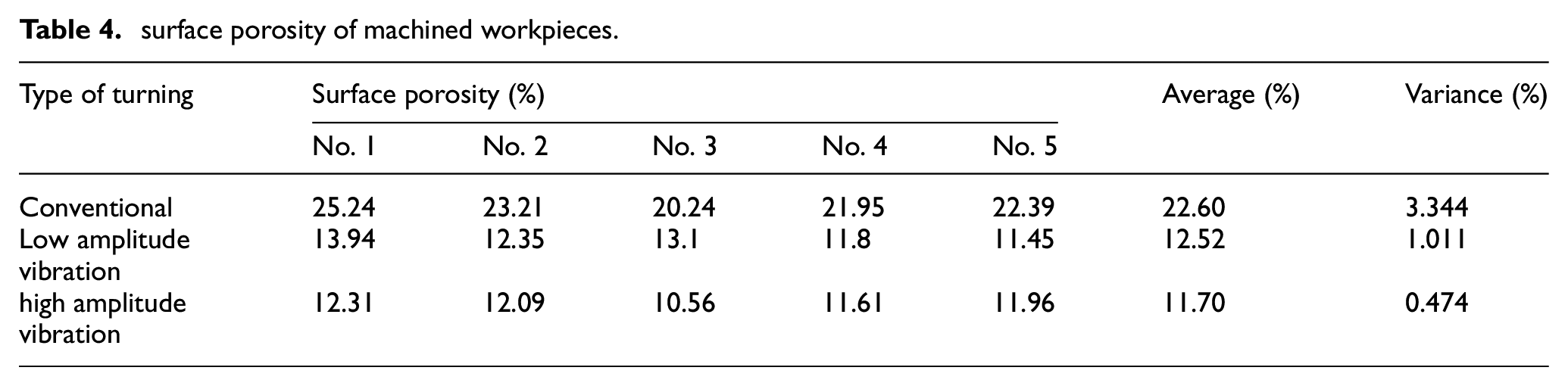
The SEM image of the workpiece’s surface machined in the conventional process is shown in Figure 10. The concavities in this image indicate that the larger pores have not been filled. The traces of shear deformation and the overlaps occurring due to the frictional rubbing of the tool tip on the workpiece’s surface are evident in Figure 10. The overlaps lead to the filling of smaller pores. Cracks have also been observed next to the surface pores (Figure 10). The density of the machined workpiece’s surface porosity measured by the processing of the SEM images is presented in Table 4.
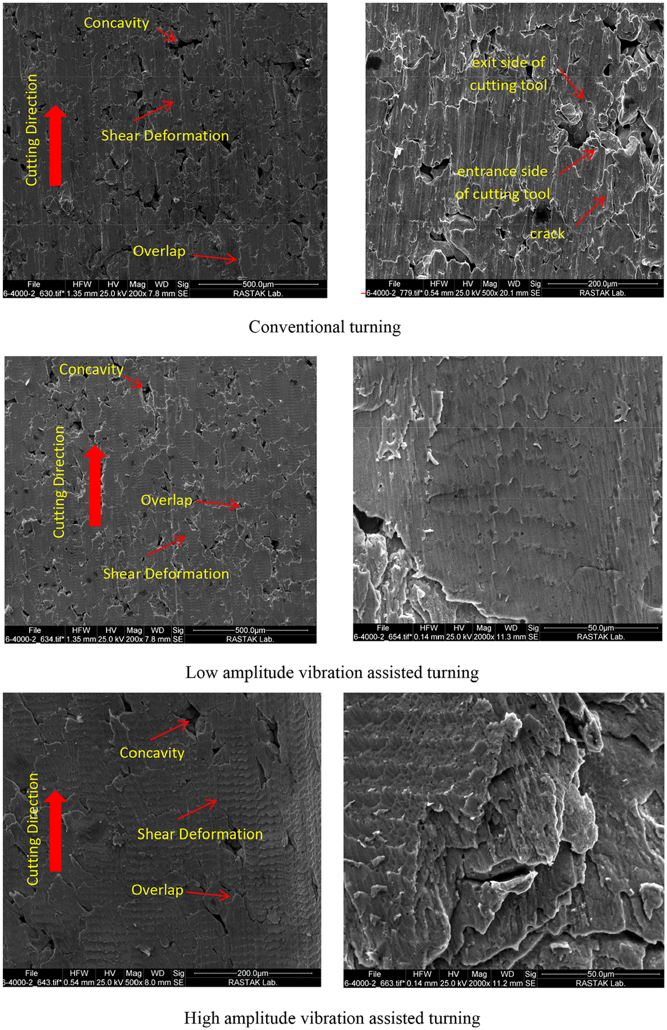
SEM images of workpiece’s surface machined: (a) conventional turning; magnification 200 (left) and 500 (right), (b) low amplitude (a = 2 µm) ultrasonic vibration assisted turning; magnification 200 (left) and 2000 (right), and (c) high amplitude (a = 6 µm) vibration assisted turning; magnification 500 (left) and 2000 (right).
surface porosity of machined workpieces.
The SEM image of the workpiece’s surface machined in Low amplitude vibration assisted turning (2 µm) is shown in Figure 10. The overlap and shear deformation are evident in the left image (part b in Figure 10). In a highly magnified image (right), the traces of the withdrawal and forward motion of the cutting tool in the ultrasonic vibration assisted machining can be seen in the form of consecutive serrations. This effect has already been reported and analyzed by Nategh et al. 32 and Razavi et al. 33
The SEM image of the workpiece’s surface machined in high amplitude vibration assisted turning (6 µm) is shown in Figure 10. The overlap of the material and the traces of shear deformation are evident in this figure. In the image with a magnification of 2000, the topography of the surface and the traces of the vibratory tool are clearly visible.
A careful examination of the conventional material removal mechanism for the porous workpieces already discussed in this paper indicate that the final topography of the workpiece’s surface is dependent on the cutting direction. The pores at the entrance side of the cutting tool are exposed to rubbing by the tool. This creates irregular edges on this side of the pores. At the other side where the cutting tool leaves pores, the edges of the pores are dug. This is in accordance with the results of Heidari and Yan. 34
It is clear from the image in Figure 10 that the pores have no cracked edges. The reciprocating (rubbing) motion of the cutting tool on the workpiece’s surfaces has probably been the reason for this positive effect. The rubbing of the cutting tool has, indeed, a burnishing effect which is beneficial to the surface quality. An in-depth study has been conducted by Nategh et al.
32
and Razavi et al.
33
on this phenomenon. A schematic of the machining forces in a vibration cycle is shown in Figure 11. In this figure, ta is start of engaging and cutting, tb is end of engaging and cutting and start of disengaging, and tc is end of disengaging and start of engaging too. The frictional force
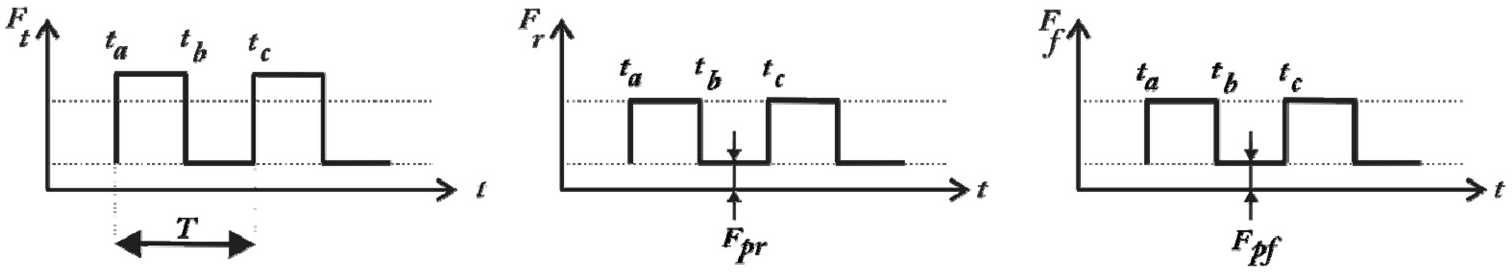
A schematic view of machining forces in a vibration cycle.
The metallography of specimens revealed further evidences of the burnishing effect of the superimposed ultrasonic vibration. The results are illustrated in Figure 12 depicting the cross sections of the upper surfaces of the machined specimens. As is clear from this figure, the depth of the compacted layer of specimen in the conventional turning is difficult to observe. Some traces of grain separation and surface roughness can be distinguished on the machined surface. The depth of the compacted layer is quite visible in the specimen turned in high amplitude vibration assisted turning. The depth of this layer is about 15 μm. The machined surface is quite smooth and free of any visible defect. These results are inconsistent with the results of Lotfi et al. 24 This implies that the addition of vibration has different influences in the turning of porous and non-porous materials.
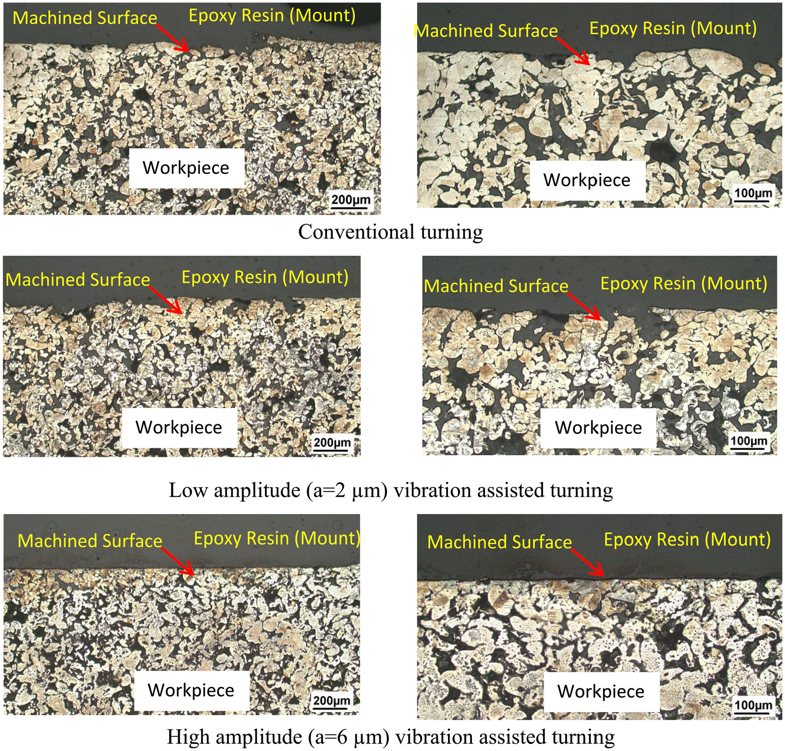
Microscope images of cross section in conventional and vibration assisted turning; magnification 50 (left) and 100 (right).
Conclusion
In this study, the effect of adding ultrasonic vibration to the cutting motion of the cutting tool in turning of porous stainless steel 316L has been investigated. The average cutting forces and the amplitude of the fluctuations of these forces reduced by superimposing vibration. The SEM images of the chips indicated that in high-amplitude vibration assisted turning, the chips were longer. This implied that the intermittent breaks of the chips in conventional turning led to fluctuations in the force components. The measurements indicated that machining of porous workpieces by ultrasonic vibration assisted turning resulted in more decrease of the surface’s porosity than the conventional turning. In SEM images of surfaces machined by the vibration assisted turning, material overlaps were observed, which was due to the frictional motion of the tool tip on the surface of the workpiece. The examination of the surface topography showed crack propagation near the edges of the pores when the workpiece was machined in conventional turning. The rubbing phenomenon occurring in the ultrasonic vibration assisted turning, however, prevented abrasion and crack to develop at the edges of the pores. The addition of ultrasonic vibration to the cutting motion could thus improve the integrity of the machined surfaces. The frictional force during the withdrawal and forward motion of the cutting tool was responsible for the improvement of the surface integrity. It was also one of the main factors in filling the surface pores. The authors’ future work focuses on optimizing the conditions by the appropriate objective function and the relevant constraints for achieving the optimal conditions of ultrasonic vibration assisted turning of porous materials.
Footnotes
Acknowledgements
The authors would like to acknowledge the help of Dr. Fatolahi, Dr. kokabi, Dr. Alamdarnejad, and personnel of Rastak laboratory.
Declaration of conflicting interests
The author(s) declared no potential conflicts of interest with respect to the research, authorship, and/or publication of this article.
Funding
The author(s) received no financial support for the research, authorship, and/or publication of this article.