
Abstract
In laser cladding, the development of rapid heating and cooling cycles generates high residual stresses and thermal gradients that lead to induce unwanted distortion in the parts. The paper deals with online monitoring of temperatures and the associated distortions in multi-layer laser cladding using pyrometers and laser displacement sensors. The alloys deposited in the present work are Stellite 6 and Inconel 718, having similar thermo-mechanical properties. The results show that variation in thermal gradients due to rapid heating and cooling allows the material to expand and contract, generating substantial distortions. In the current investigations, Stellite 6 deposits generated 28%, 21%, 15% higher deflection at 12 mm/s, 16 mm/s, 20 mm/s scan speeds respectively; and 23%, 20%, 17% at 2400 W, 2900 W, 3400 W laser power compared to Inconel 718. Irrespective of the coating material, the second layer cladding induced 10% to 30% lower distortion than the first layer because of the reduction in temperature gradient. However, Inconel 718 clads measured 10% to 15% less melt pool temperatures than Stellite 6. The study reveals that different cladding materials deposited under similar process conditions have greater impact on distortion and temperature. At last, the investigations provide an optimum set of parameters to produce homogeneous cladding with moderate deflection and temperature for both the alloys.
Introduction
Laser cladding (LC), also known as Direct Energy Deposition (DED) process, is an advanced surface modification technique used to repair and/or refurbish the damaged/worn-out parts. 1 The process uses a laser heat source to melt, the coaxially fed powders and the substrate material simultaneously to form a thin layer. 2 In cladding, mainly the deposition materials are in powdered form which provides higher flexibility to produce a variety of functionally graded coatings. 3 The LC process can build high wear and corrosion resistant coatings, upto 2 mm thick. 4 It has various advantages like low dilution, high deposition rates, repeatability, metallurgical bond formation, etc.5,6 Despite of that, the high rate of thermal cycles (≈105 k/s) induced in cladding lead to the generation of large thermal gradients (G) (due to melting). 7 As a result, residual stresses and out-of-plane distortions are developed in the components, 8 affecting geometrical accuracy, 9 mechanical, 10 and microstructural properties. 11 Hence, these distorted parts require high end post-machining operations, adding cost to overall repair and also affecting the clad quality. To understand and minimize this distortion problem during laser cladding, several studies on monitoring aspects, such as in situ, post-processing, numerical models were conducted; out of which in situ measurements are widely used these days due to their real time data acquisition and repeatability.
Several investigations were carried out to understand the distortion mechanism in LC using different online monitoring techniques, setups, and sensors. Such as, Ocelík et al. measured the strains generated in LC using 3D digital image correlation (DIC) method and found that strain gets reduced at high scan rates and low temperatures. 12 Corbin et al. studied the effect of preheating temperature and substrate thickness on distortion in cladding Ti6Al4V using laser displacement sensors (LDS) and thermocouples. It is observed that the decrease in substrate preheating gives low distortion in thin substrates and vice versa. 13 Heigel et al. tracked in situ out-of-plane distortion (LDS) and temperature (Pyrometers) while cladding at different process conditions, 14 and found that the longitudinal bowing and transverse angular distortion mode were developed simultaneously in the laser cladding process. Further, a study on the effect of interlayer dwell time on residual stresses and distortion by Denlinger et al., noticed that increase in dwell time for Inconel 625 reduces distortion and increases for Ti6Al4V. 15 Heigel et al. reported that powder feedstock generated larger deformation and temperature compared to wire form cladding. 16 Moreover, the distortion and temperature generation in cladding with unconstrained substrate condition performed by Thawari et al. have shown that low scan speeds and high laser powers generate higher distortion. 17 However, Dunbar et al. measured distortion using Differential Variable Reluctance Transducer (DVRT) sensor for rotating and constant deposition with different scan patterns; against which rotating patterns induced 38% low distortion than constant one. 18 Whereas, Coherent Gradient Sensing (CGS) technique was used by Li et al. to determine the deflection rates. 19
The above literature investigates and compare different aspects like scan pattern, interlayer dwell time, forms of cladding material, substrate thickness, preheating, etc. Further, few studies indicate that different depositing materials have different effect on distortion,20,21 and is noteworthy to consider this aspect while depositing different alloys having similar thermomechanical properties. However, despite of the past investigations, available data was found to be insufficient to understand the role of cladding materials on temperature and distortion accumulating during multi-layer deposition. Also, previous studies were carried with a single displacement sensor which only provides the information at a particular location. Apart from this, past attempts on distortion monitoring with laser cladding were performed mainly with constrained conditions which may further induce additional residual stresses.20,22 Hence, an attempt was made to bridge this gap and to better understand the effect of cladding materials on in-process temperature and distortion.
In the present study, Stellite 6 (ST6, Co-based) and Inconel 718 (IN718, Ni-based) alloys were used as two different cladding materials and are deposited under identical process conditions. The selected alloys possess near to similar thermo-mechanical properties, that is, melting point, thermal expansion coefficient, specific heat capacity and density. Moreover, both the alloys have the ability to maintain their structural properties at elevated temperatures with good corrosion resistance.23,24 Owing to this, Almstrom et al. used Inconel 718 and Stellite 6 coatings for valve seat applications and found that IN718 is superior. 25 Thawari et al. compared ST6 and IN718 claddings for geometrical, mechanical, and microstructural properties. 26 The work attempted includes study of melt pool and substrate temperature history using multiple pyrometers and distortion with the laser displacement sensors. The online monitored data is analyzed to evaluate the effect of cladding powder on temperatures and the associated distortions. The study reveals that the rate of deflection is mainly affected by thermal gradients generated due to rapid heating/cooling. It is found that ST6 and IN718 deposits generate different magnitudes of distortion. The work concludes that scan speeds have a greater impact on distortion than laser power for both the alloys. Finally, an optimum set of parameters are obtained for Stellite 6 and Inconel 718 cladding which can induce minimum distortion.
Experimental procedure
Materials
In the present study, multilayer cladding of commercially available Stellite 6 and Inconel 718 alloys were performed on SS316 substrate (size: 120 mm × 65 mm× 8 mm) covering a clad area of 100 × 55 mm. 2 Both ST6 and IN718 powders are having a particle size range: 30 µm to 100 µm in dia. Table 1 summarizes the elemental composition of clad powders obtained through X-ray fluorescence (XRF) analysis (SHIMADZU EDX-7000) and the substrate through atomic emission spectroscopy (AES). Prior to cladding, samples were cleaned with acetone for oil and dust particles removal to avoid non-uniform absorption of laser energy.
Elemental composition (Wt%).
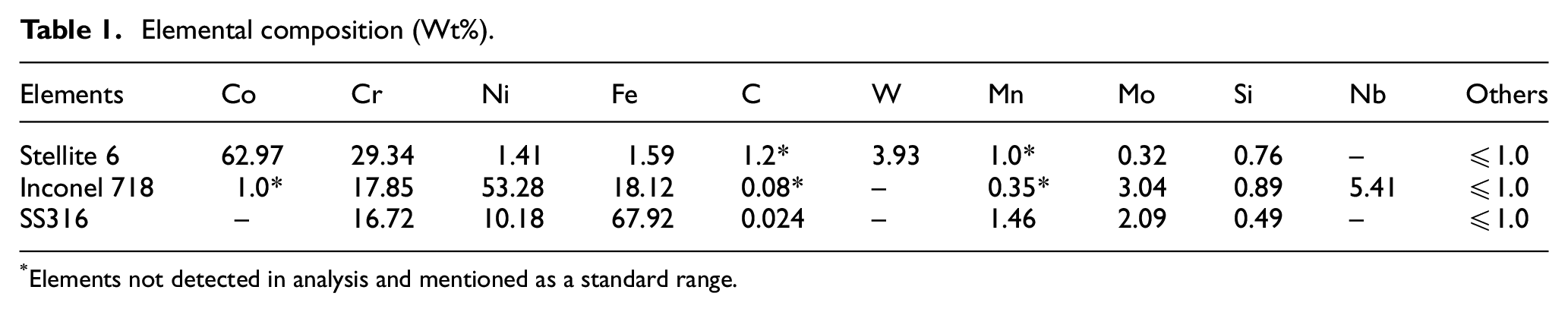
Elements not detected in analysis and mentioned as a standard range.
Setup
The experimental setup consists of a fiber-coupled diode laser cladding system (Laserline LDF 4000-100) having 4 kW maximum discharge power with spot dia. of 5.5 mm. A gravimetric powder feeder (UNICOAT, USA) was used for powder feeding with Ar as carrier and shielding gas to avoid contamination and oxide formation in the melt region.
Process parameters
Initial trials were performed with single track deposition of both the alloys that gave optimum process parameters. A total of 18 samples (9 for each alloy) were prepared at different parameters, listed in Table 2, keeping other parameters constant. Each sample consists of two layers of cladding with sixteen unidirectional longitudinal tracks in each layer and having a 30 s dwell time between layers. Additionally, the combined effect of laser power and scan speed was studied using Linear Heat Input (LHI) metric as defined by equation 1:
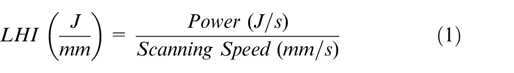
Process parameters.
Monitoring
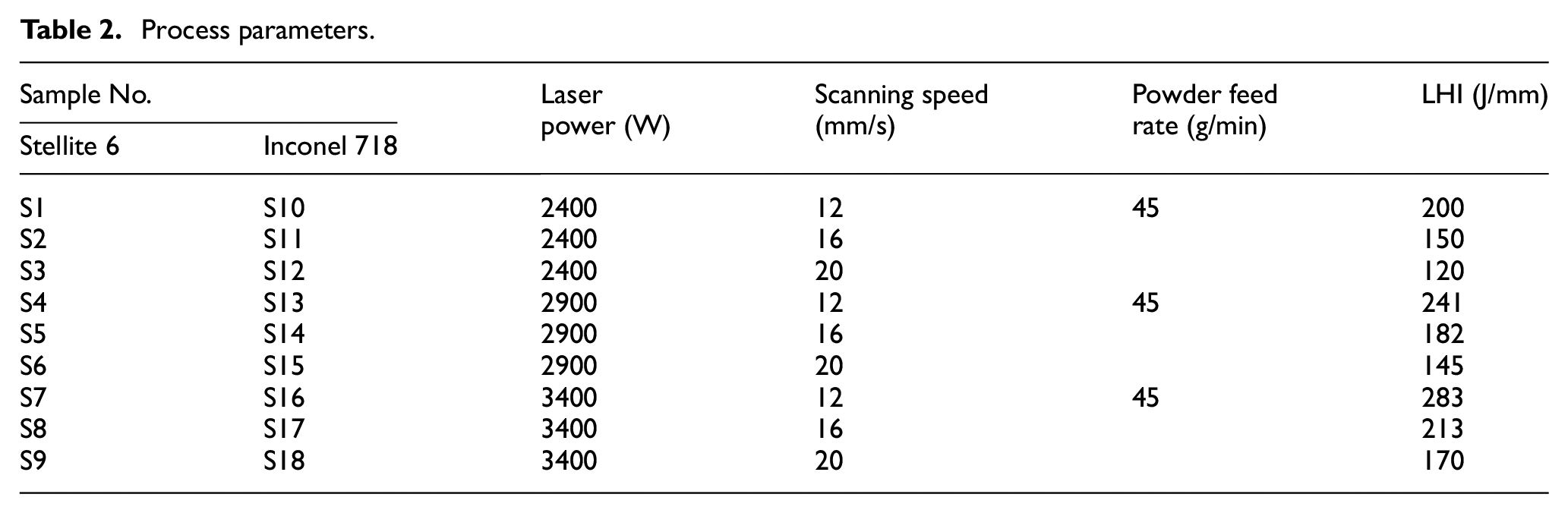
The distortion monitoring was performed using five displacement sensors (Model-LE250, Banner, USA) having 1 mm laser spot dia. and accuracy of ±1 µm, placed beneath the substrate. The data acquisition system consists of NI9205 (National Instruments, USA) and LabVIEW software for data processing. The melt pool temperature was captured using a non-contact pyrometer, CTM-2CF75H1 (Micro-Epsilon, USA) with a measuring range: 450 to 2000°C and ±0.3% accuracy. The substrate temperature was measured with five K-type pyrometers, CS-SF15-C1 (Micro-Epsilon, USA) and installed beneath the substrate. These sensors can measure temperatures from 0 to 1030°C with ±1.5% or 1.5°C accuracy and data acquisition through NI9213 (National Instruments, USA). Figure 1 shows the sensor position schematic with ±1 mm positioning error. To avoid any data loss, data acquisition was started 20 s prior to cladding and stopped 2 min after the deposition.
Sensor position schematic (left) and experimental setup (right).
A fixture was designed and fabricated to accommodate all sensors and the substrate. The plate was supported with four steel balls that act as point contact in an unconstrained condition. The out-of-plane displacement of the substrate during cladding is restricted with the help of four loosely tightened bolts. A 1 mm thick MS plate was attached to the fixture to prevent the sensors from laser heat and unmelted powders. The complete experimental setup with all sensors and substrate holding is shown in Figure 1. Further, the post-process deflections were also measured with the same setup and sensors.
Results and discussion
Distortion
The in situ deflections through LDS are investigated to understand the effect of depositing materials and process parameters in multi-layer laser cladding process. Figure 2 shows the distorted samples, graphical representation, and the deflections measured during cladding for samples S6 (ST6) and S15 (IN718). The results show near-similar deflection trends for both the alloys, that is, corners moving upward (D1-D4) and downward at center (D5). Further, it is observed that the corner sensors have shown similar deflections despite of their different locations. Hence, an average of these four recordings is considered to be the maximum corner distortion. Also, similar deflection profiles were observed for the remaining samples. The deflection plots in Figure 2(c) and (d) are in good agreement with the actual deflections developed, Figure 2(a) and (b); which is in line with other research findings.14,27 The results indicate that cladding in longitudinal direction induces mainly longitudinal bowing mode of distortion irrespective of clad materials.
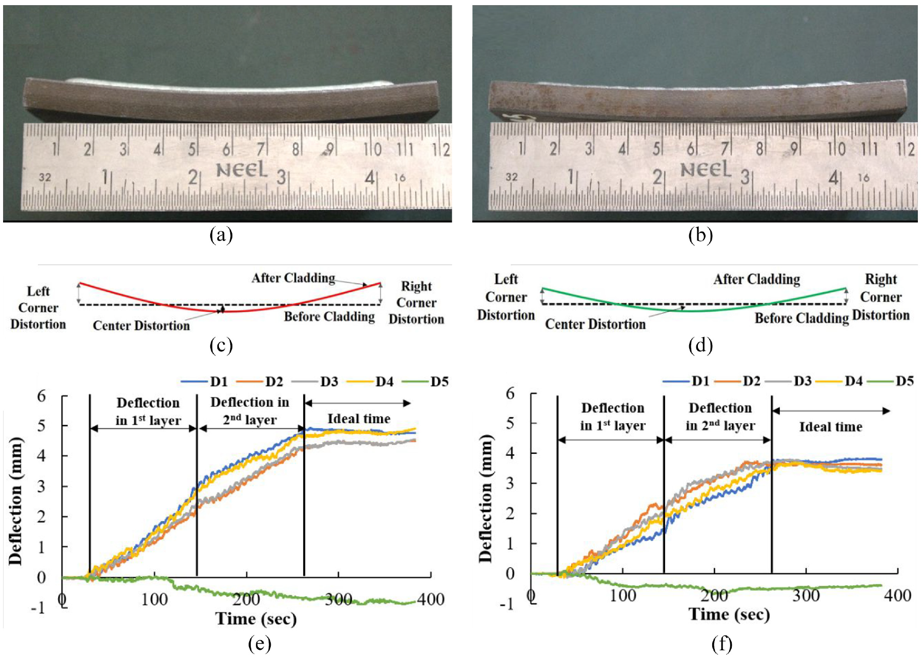
Distorted samples, Graphical representation, Measured deflection in S6, Stellite 6 (a, c, e) and S15, Inconel 718 (b, d, f).
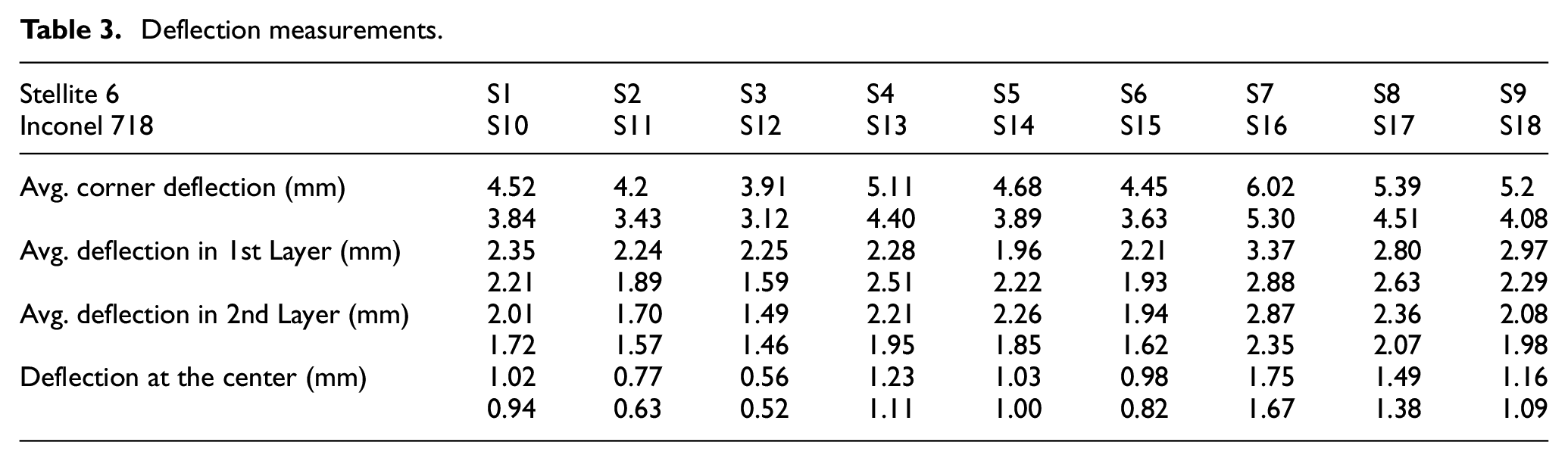
The deflections measured under different process conditions are summarised in Table 3. The data indicates that distortions in Inconel 718 samples are lower than those of Stellite 6. The results revealed that an increase in laser power and decrease in scan speed generates larger deflections, regardless of the clad material. Whereas, no direct relationship was found for LHI in both the alloys, as reported earlier.14,27 In ST6 cladding, maximum deflection of 6.02 mm (corner), 1.74 mm (center) in S7, and a minimum of 3.89 mm (corner), 0.57 mm (center) for S3 are obtained. On the contrary, maximum and minimum deflections of 4.89 (corner), 1.06 mm (center), and 2.73 (corner), 0.45 mm (center), respectively were developed for S16 and S12 with IN718. These deflections are 28%, 21%, 15% more when cladded with ST6 at 12 mm/s, 16 mm/s, 20 mm/s of scan speed respectively, as compared to IN718. Similarly, the average lower distortion of 23%, 20% 17% was recorded at 2400 W, 2900 W, 3400 W laser power with IN718. Further, the deflections measured in depositing second layer with both the alloys are 10% to 30% lower than the first layer. The results indicate that distortion is influenced more by scan speed than laser power.
Deflection measurements.
Further, investigations are carried on the number of peaks and valleys that appear after equal time intervals in deflections. On further analysis, it is found that these peaks belong to individual tracks deposited showing a downward bend at the corners during deposition and an upward bend during solidification. Whereas, an opposite behavior is observed at the central region. The maximum deflections obtained while depositing individual tracks with ST6 and IN718 (S6, S15) are plotted in Figure 3. The results reveal that deflection during ST6 cladding is 15% to 25% higher than IN718 under identical process conditions. However, the substrate deflection keeps on increasing with the number of tracks for both the alloys. Also, similar trends were observed in the remaining samples.
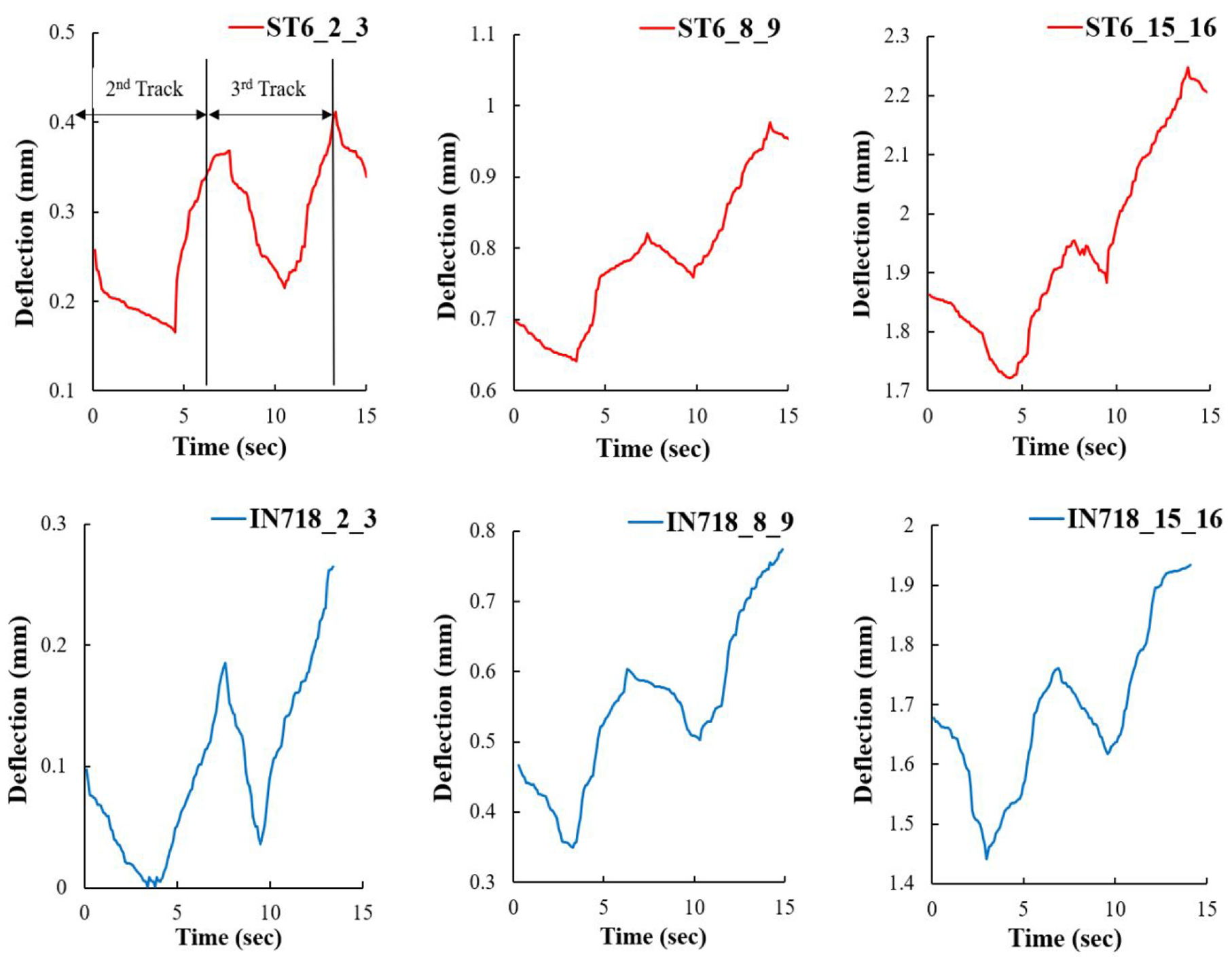
Deflection during individual track deposition in samples S6 (ST6) and S15 (IN718).
The post-process measurements were carried to evaluate and differentiate between the pre- and post-distortion. The results have shown minimum or negligible (2%–3%) post-process distortion. It is presumed that the residual stresses developed during cladding are adjusted/retained by the substrate distortion because of unconstrained condition. Hence, post deflections are considered as the final distortion in the substrate and is shown in Figure 4.
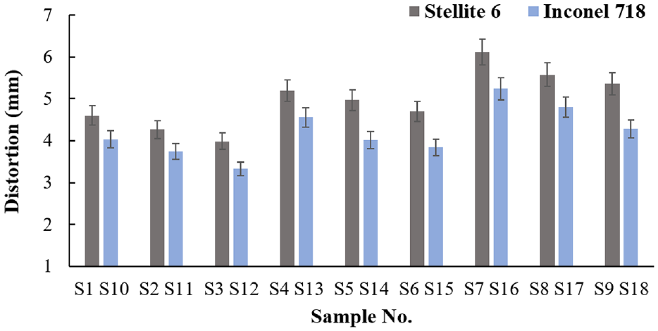
Maximum distortion in all samples.
In situ temperature monitoring
The rapid heating and cooling phenomenon in laser cladding leads to development of high thermal gradients, resulting in uneven expansion and contraction that generate distortions. Hence, to understand the role of thermal gradient on distortion, melt pool and bottom surface temperatures were monitored using multiple pyrometers.
Melt pool temperature
The melt pool temperatures measured in cladding S6 (ST6) and S15 (IN718) samples are plotted in Figure 5. The dotted line shows the average melting point of ST6, IN718 and SS316 (≈1350°C). The plots show rapid heating and cooling in the melt region, which is in good agreement with the previous work.17,28 Irrespective of the cladding material the samples showed a similar trend for thermal history in both the layers, whereas at the beginning of second layer surface temperatures were increased by 25% to 30%. This temperature rise is due to the short dwell time present between layers and heat accumulation in multi-track deposition. Also, the melt pool temperatures in second layer deposition are observed to be higher than the first layer. Similar plots with different temperatures range were recorded in rest of the samples.
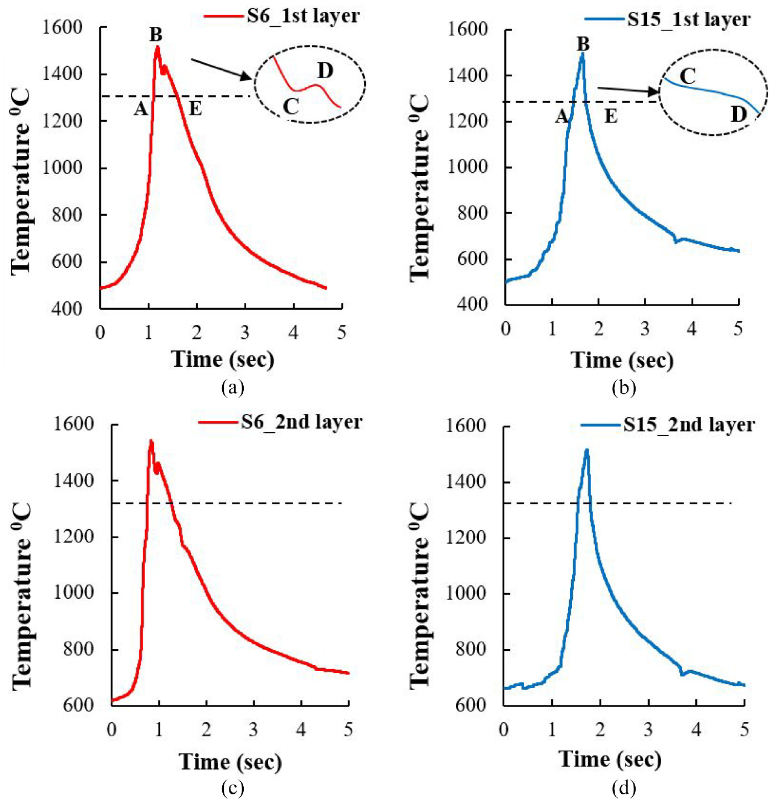
Melt pool temperature plot for S6 and S15: (a) Stellite 6 (1st layer), (b) Inconel 718 (1st layer), (c) Stellite 6 (2nd layer),(d) Inconel 718 (2nd layer).
Figure 6 shows the maximum melt pool temperatures obtained in multi-layer deposition. The results indicate that the temperatures generated in ST6 claddings are slightly more than IN718 except for S11 and S12. The samples S7, S3 from ST6 and S16, S10 from IN718 have generated maximum and minimum temperatures respectively. The temperatures recorded are well above the melting temperatures of cladding and substrate, indicating formation of a metallurgical bond. The increase in laser power and decrease in scan speed shows an increase in the melt pool temperatures, which is also valid for increasing LHI, because of high heat addition per unit length. A 70 to 90°C temperature rise is measured between two consecutive scan speeds, due to the variation in interaction time available between the substrate and laser heat source. The samples S2, S6 from ST6 and S11, S15 from IN718 have recorded nearly same temperatures range due to near similar LHI values.
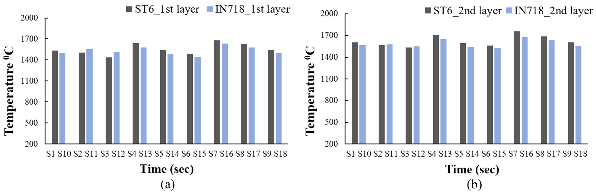
Maximum melt pool temperatures at first- and second-layer cladding ST6 and IN718.
In Stellite 6 cladding (Figure 5a), the temperature rises rapidly as the heat source reaches the measuring point, attaining maximum temperature till point B and further drops to point E after the laser moves away from the location. Whereas, between B and E, a slight increase in temperature is observed from C to D. This temperature rise is due to the formation of hard carbides in the Co-rich matrix that liberates heat energy during exothermic reaction. 29 While, with IN718, no such temperature deviation is observed due to low carbon content, instead a solid-liquid equilibrium state is seen from C to D (Figure 5b). This region shows a rapid decrease in cooling rates and becomes nearly zero, due to the heat released from latent heat of solidification 28 and the length indicates elemental segregation in Ni matrix. These results aid us in monitoring in situ carbide and other phases formation in ST6 and IN718 cladding.
Substrate temperature
The measured substrate bottom surface temperatures for S6 and S15 is shown in Figure 7. It is observed that the sensors T1, T2 and T3, T4 have measured near similar temperatures because of their respective positions. The central sensor has recorded maximum temperature due to heat accumulation in the middle region during multi-track deposition. As a result, T5 temperature data was considered as the maximum substrate temperature for further analysis and is shown in Figure 8. Similar observations were also made in other cladded samples.
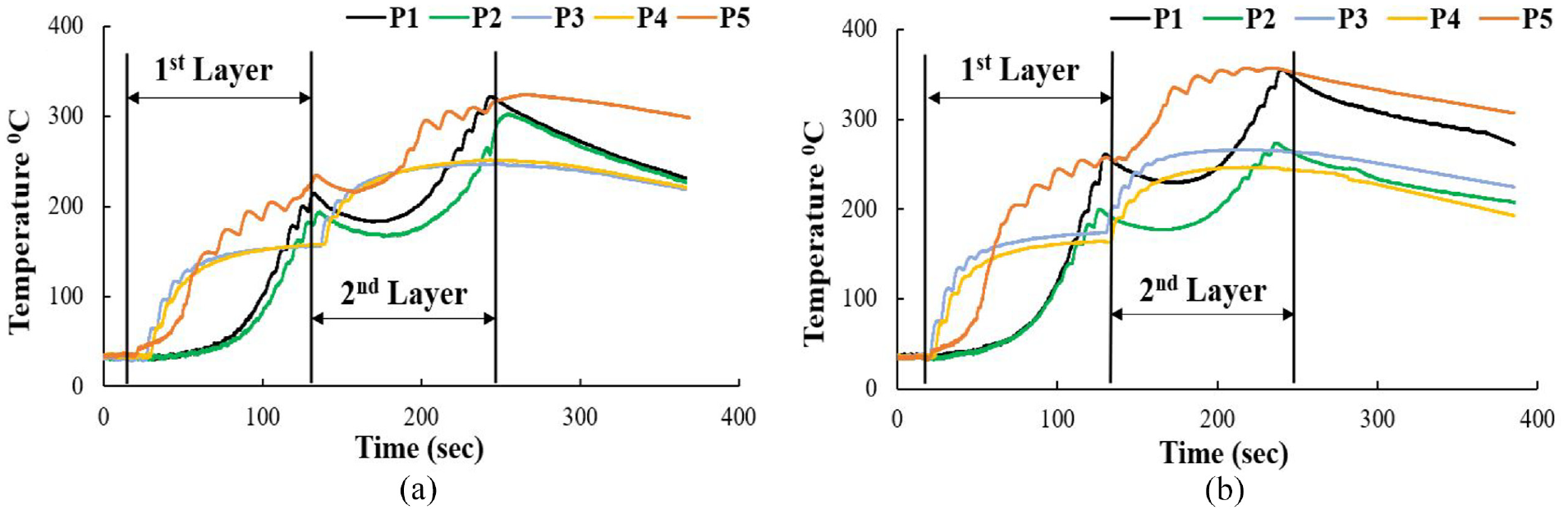
Substrate bottom temperature in samples (a) S6, (Stellite 6), (b) S15 (Inconel 718).
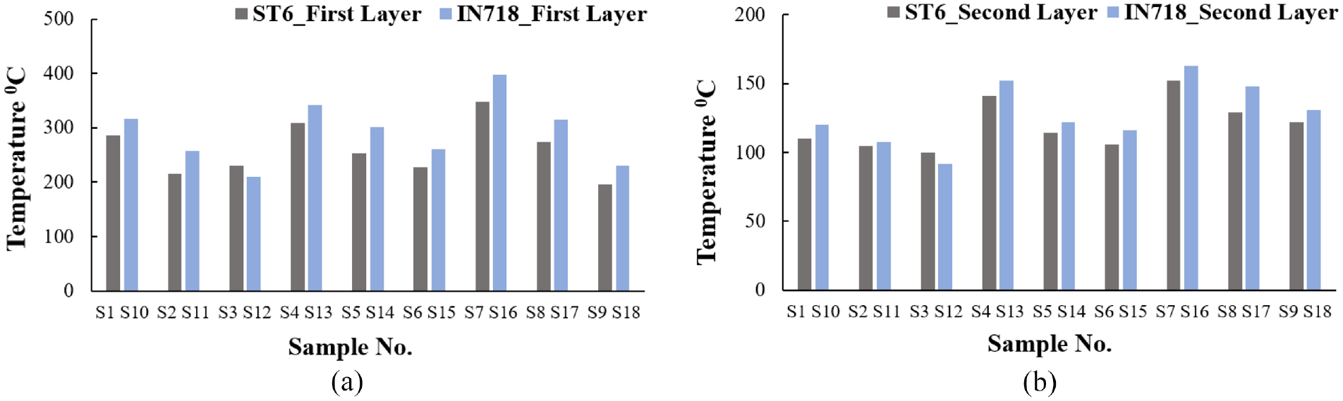
Maximum temperature in ST6 and IN718 cladding during (a) First Layer (b) Second Layer.
The samples S7, S3 in ST6 and S16, S10 in IN718 have shown maximum and minimum temperatures respectively. However, Stellite 6 deposits experienced 15% to 20% low bottom temperature than Inconel 718. In both the alloys cladding, decrease in scan speed increases the substrate temperature, which is 50% (12 mm/s) and 22% (16 mm/s) more than with 20 mm/s. This is due to high interaction time at low scan speeds, that adds more heat to the material as shown in Figure 6. Contrary to this, an increase in laser power measures higher base temperature. Apart from this, the temperatures measured during second layer deposition are approximately 45% to 55% lower than the first layer, because of the reduction in heat transfer through the first layer.
From the thermal history (Figure 7), few temperature peaks were observed, when the heat source passes the measuring point. As the laser moves away from the point, such peaks get diminished. On further analysis, it was found that such peaks belong to individual tracks and hence investigated to evaluate the temperature during each track cladding. Figure 9 shows the temperature peaks while depositing tracks in S6 and S15 samples. Here, the magnitude of temperature peaks during initial tracks deposition is high compared to the middle and last tracks. Because, at the start of deposition bulk substrate is at ambient temperature (i.e., 27°C); and the top surface is at higher temperature (>1350°C), due to which the generated heat during coating conduct rapidly towards the bottom, giving higher peaks. As the process continues, the base surface attains some rise in temperature, reducing the temperature difference, and so the temperature peaks. The results indicate that ST6 generate 12% to 16% lower temperatures than IN718, which is due to high thermal conductivity of ST6 alloy.
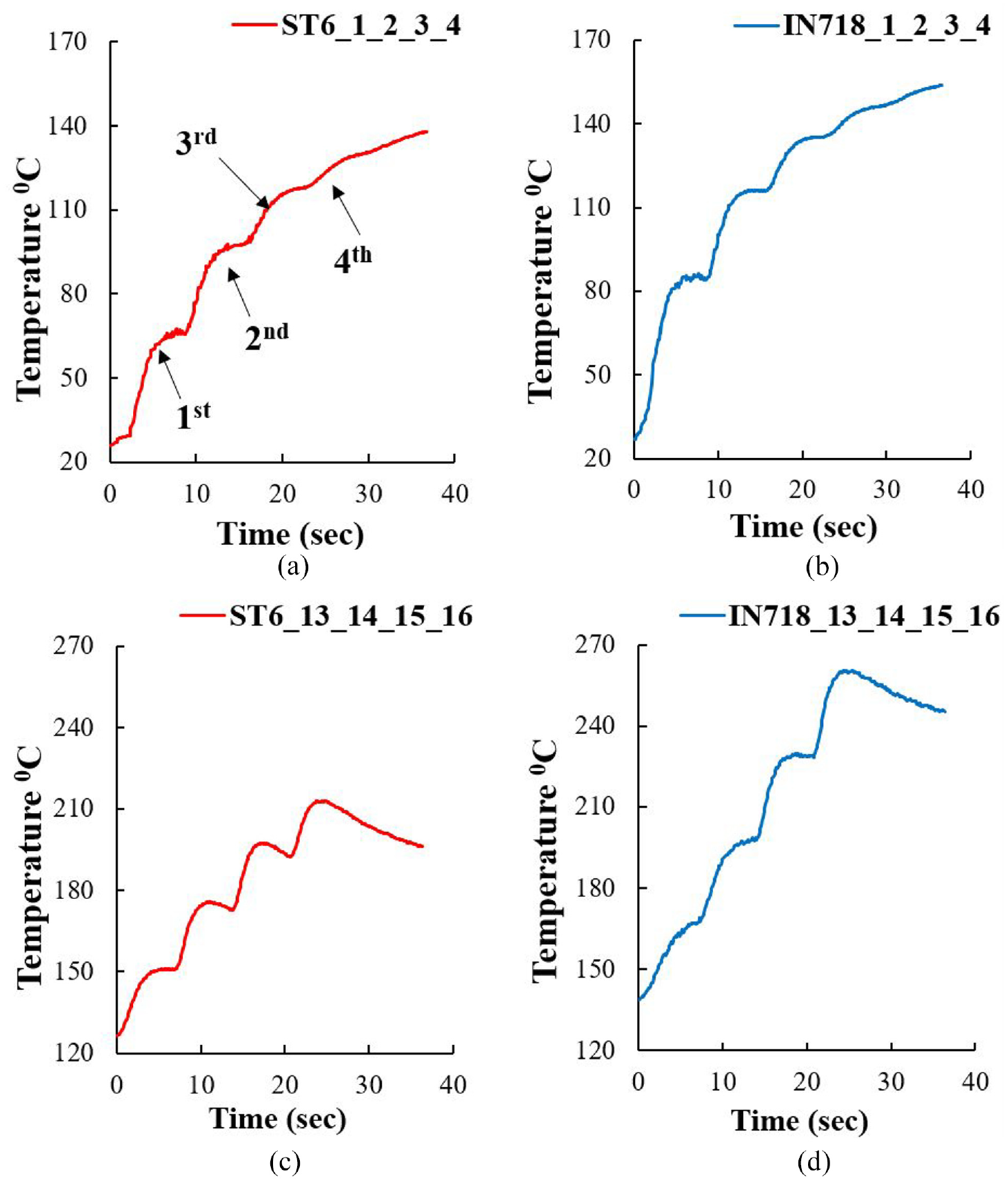
Temperature plots during individual track cladding in samples S6 and S15.
Discussion
Effect of thermal gradient and cladding material on distortion
The substrate distortion during laser cladding is a result of uneven expansion and contraction, which occur at the interface region. This phenomenon takes place due to large thermal gradients developed along the thickness. 13 To investigate the effect of thermal gradients on distortion, melt pool and bottom temperatures were analysed. From Figure 5, it is seen that the temperatures generated in the cladding area are very high (appx. 1560°C in ST6, 1485°C in IN718) and are well above the melting temperature. Whereas, the maximum base temperature measured during initial tracks are 120°C (ST6) and 150°C (IN718), respectively as shown in Figure 9. This implies the generation of large thermal gradients along the thickness. Besides, when the clad material and substrate are in a molten state due to laser heating, expansion occurs at the interface; which gets restricted by the bulk substrate due to low temperature. This constrained condition imposes compressive stresses at the top and interface regions, resulting in a hogging-like profile (i.e., bending corners downward and center upward, Figure 10(b). Similarly, after the track deposition, the clad material cools down and will contract due to rapid heat transfer (Figure 5). Hence, tensile stresses were generated during solidification which develops a sagging like profile (Figure 10(c), opposite to hogging). This is in agreement with the deflection trends obtained during individual track deposition (Figure 3). At the same time, when the substrate tries to retain its original position (during solidification), the next track deposition starts and the substrate experiences similar distortion phenomena again. As a result, the substrate begins to deflect further from the point where contraction from previous track ends and adds more substrate deflection. Whereas, the overall temperature also increases simultaneously with increase in number of tracks (Figures 7 and 9), resulting a small temperature difference and so the deflection (Figure 3). Figure 10 shows the depiction of distortion phenomena during individual track deposition.
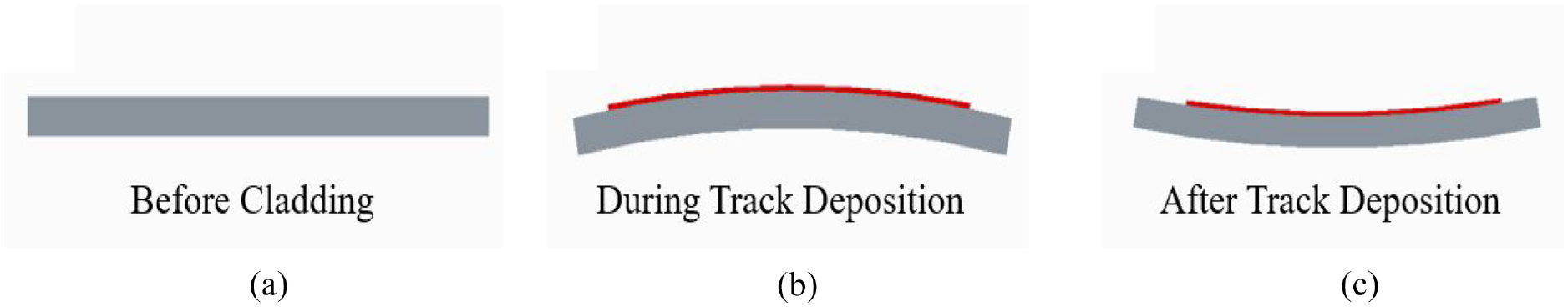
Distortion phenomenon in individual track deposition.
In the present study, an average of 10% to 15% higher melt pool temperatures are obtained in ST6 deposits than IN718. Also, 15% to 20% lower substrate temperatures are recorded with ST6. Owing to this, large thermal gradients are generated in ST6 clads which allow more expansion during cladding. Also, the coefficient of thermal expansion (CTE) of Stellite 6 alloy (13.9–17.4 µm/m k) is higher than Inconel 718 (13.2–16 µm/m k) which contributes for the high expansion. 30 Hence, the distortions in ST6 are found to be 15% to 25% more. The in situ data is in accordance with the theoretical and experimental results; hence the study reports that deflection magnitude primarily depends on generated thermal gradients and CTE.
Furthermore, the temperatures prior to second layer deposition shows an increment in heat accumulation at the top surface of first layer (Figure 5) and bottom substrate (Figure 7). This results in reduction in the temperature difference along thickness and associated stresses, giving low substrate deformation (Table 3). Compared to IN718, the large deflection in ST6 second layer is because of its high thermal conductivity (14.7 W/m k), allowing faster heat dissipation than IN718 (11.4 W/m. k).
Effect of process parameters on distortion
As discussed in the previous section, temperatures in laser cladding process play a vital role on distortion development, which changes with process parameters. In the present study, laser power and scan speed were varied to investigate their effect on distortion.
Scan speed
The effect of scan speed on distortion is plotted in Figure 11. The results indicate that low scan speeds induce higher distortion. In ST6 cladding, 13% to 15% higher distortion at 12 mm/s and 3% to 7% at 16 mm/s were obtained compared to 20 mm/s of scan speed. Whereas, with IN718, it is 18% to 23% at 12 mm/s and 7 to 10% at 16 mm/s.
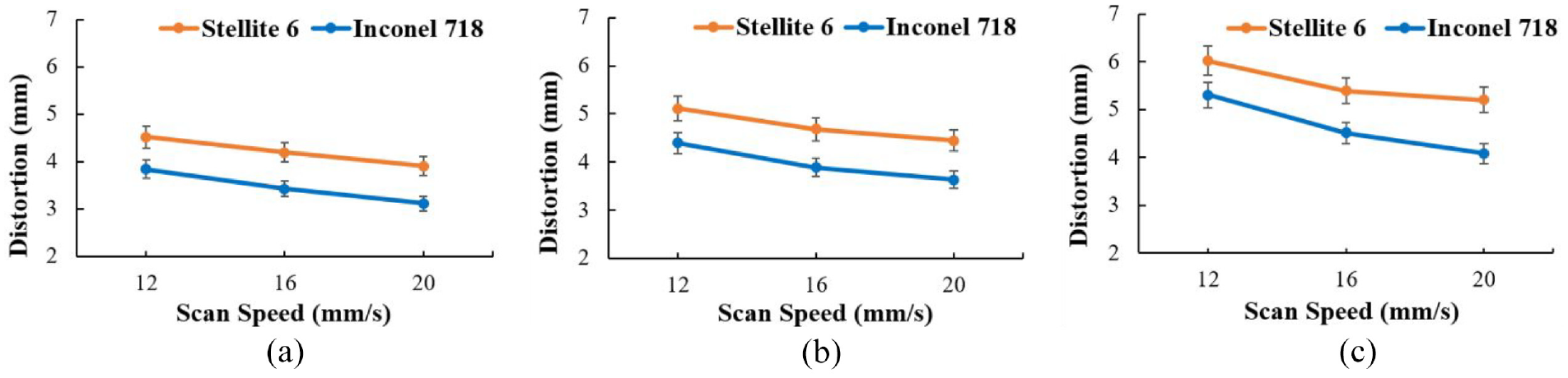
Effect of scan speed on distortion at (a) 2400 W, (b) 2900 W, (c) 3400 W.
To understand the effect of scan speed on distortion, temperature data is analyzed. The data shows that the melt pool life span i.e., length AE (Figure 5(a) and (b)), varies with scan speed. This span was calculated for all the samples and indicates the time for which the materials are in liquid state during deposition; and plotted in Figure 12. The plot shows that increase in scan speed from 12 mm/s to 20 mm/s shows decrement in melt pool life span from 738 ms to 554 ms in ST6 and 594 ms to 434 ms in IN718 at constant laser power of 2900 W (Figure 12). This is due to the increase in interaction time between the laser and substrate at low scan speeds which generates high melt pool temperatures and thereby large span (AE). The results indicate that at 12 mm/s the clad zone maintains elevated temperatures for about 30% to 35% more time than at 20 mm/s. Hence, the melt pool experiences more expansion/contraction during deposition, inducing high deflections at low scan speeds. While, cladding at high scan speeds evidenced small melt pool span and rapid heating/cooling cycles. This phenomena gives rapid solidification rates at high scan speed,31,32 providing less time for expansion. As a result, low sagging and hogging per track were measured at 16 mm/s and 20 mm/s which causes the substrate to deforms less as compared to 12 mm/s of scan speed.
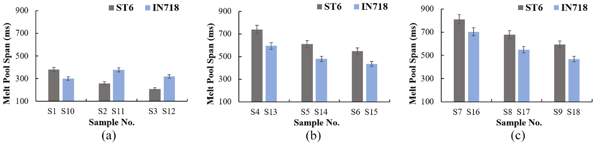
Effect of scan speed on melt pool lifespan at (a) 2400 W, (b) 2900 W, (c) 3400 W.
In all ST6 samples, length AE is 10% to 12% more than IN718 deposits which confirms that ST6 experiences more expansion/contractions. Also, the heat energy available at the clad region is slightly more for ST6 than IN718 due to high thermal conductivity. As a result, ST6 clads dissipates heat rapidly, resulting in low bottom temperatures (Figure 8) and large thermal gradients (G). Whereas, the G value is high for 16 mm/s and 20 mm/s scan speeds because of the high solidification rates. Hence, this combined effect of large melt pool lifespan and increased G allows ST6 samples to deflect more than IN718.
Laser Power
The effect of laser power on distortion at constant scan speeds is shown in Figure 13. The results show that with increase in laser power increases the substrate distortion. In ST6, the distortion is 11 to 14% higher at 2900 W and 28% to 33% at 3400 W compared to 2400 W. Whereas, IN718 has generated 13% to 16% and 31% to 38% more deflection under identical conditions. Here, ST6 induces 18% to 25% at 2400 W, 16% to 23% at 2900 W, and 14% to 27% at 3400 W higher deflection than IN718.
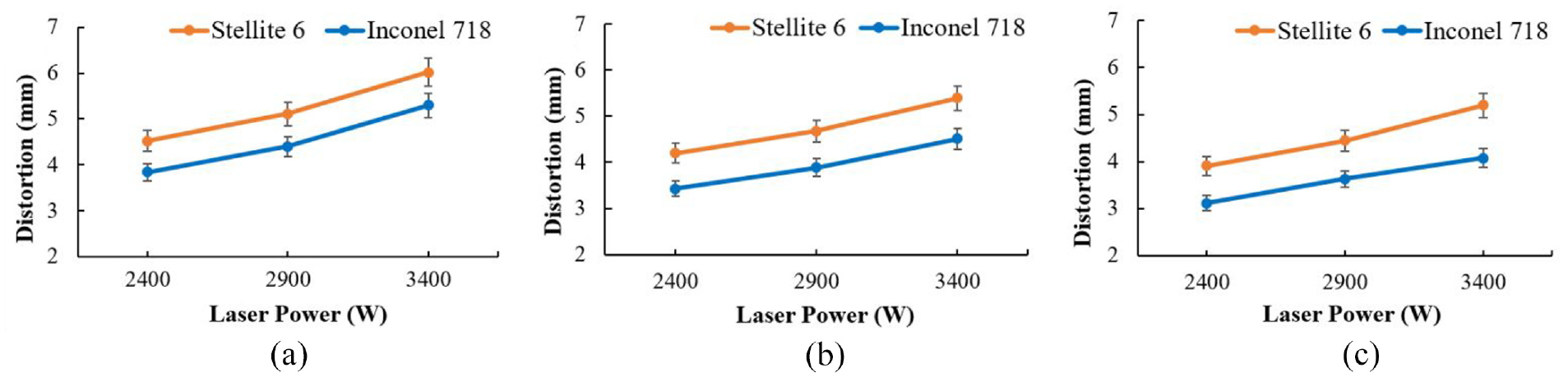
Effect of laser power on distortion at a) 12 mm/s, b) 16 mm/s, c) 20 mm/s.
At low powers, the heat energy supplied to the clad area is reduced due to laser power attenuation for constant powder feed and scan speed than at high laser powers (Figure 6). This results in the decrease in top surface temperature which further reduces the substrate temperature. An opposite phenomenon is observed when cladding at high powers. The decrease in laser energy at 2400 W generates a small melt pool area and hence the lifespan AE, as in Figure 12. Due to this the temperature difference (G) along the thickness increases and reaches highest at the interface (clad and substrate). 33 The increase in G increases the solidification rate indicating less time for ST6, IN718 claddings to expand more during deposition (Figure 12). Hence, low distortions were observed in the substrate. Similarly, at high power due to low laser depletion, the substrate melting increases and so does the life span; leading to further increase in expansion/contraction and hence the substrate distortion. These observations are in good agreement with the in situ data, shown in Figure 4. In IN718 deposition, a part of laser energy is reflected back because of its high thermal resistivity at elevated temperatures, 34 and the clad temperature reduces (Figure 6). Hence, low melt pool temperatures are observed compared to ST6 under similar conditions, resulting in low plastic deformation.
The in situ measurements reveal that ST6 and IN718 clads develop measurable distortions even though the process induces low heat input to the substrate. The study suggests 2900 W, 16 mm/s, 45 g/min for Stellite 6 as optimum parameters, and for Inconel it is 2900 W, 12 mm/s, 45 g/min to produce a homogenous deposit with moderate distortion. Apart from this, the study recommends substrate pre-heating to decrease the thermal gradient and related distortion. Further, buffer layer addition (with intermediate CTE) can also be an alternative to reduce the expansion rate at the interface, that gives low distortion.
Conclusions
A multi-layer laser cladding of Stellite 6 and Inconel 718 alloys at different process parameters was successfully carried on SS316 substrate. To investigate the effect of clad materials on distortion and temperature, online measurements were undertaken. The results are in good agreement with theoretical and experimental measurements. Some of the important conclusions were derived from the investigations.
The in situ temperatures shown rapid heating and cooling cycles in the melt pool region which allows the clad and substrate materials to expand and contract at different rates, leading to substrate distortion. The Stellite 6 deposition at 12, 16, 20 mm/s scan speeds generate 28%, 21%, 15% and at 2400, 2900, 3400 W laser power, 23%, 20%, 17% more deflections as compared to Inconel 718 respectively. The IN718 deposits recorded 10 to 15% lower melt pool temperatures than ST6 under identical conditions. Further, a high melt pool lifespan was measured at low scan speeds which induces large deflection. Irrespective of the cladding alloy, 15% to 20% higher temperatures at the top and 45% to 55% at the bottom were generated at the start of second layer deposition, resulting in low thermal gradient and thus developing 10% to 30% low deflections than the first layer. The overall analysis suggested optimum process parameters within the selected range, that is, for Stellite 6: 2900 W, 16 mm/s, 45 g/min, and Inconel 718: 2900 W, 12 mm/s, 45 g/min.
Footnotes
Acknowledgements
The authors also express their sense of gratitude to M/s Shreenath Engineering Industries, Nagpur for extending their laser cladding facility for experimentation.
Declaration of conflicting interests
The author(s) declared no potential conflicts of interest with respect to the research, authorship, and/or publication of this article.
Funding
The author(s) disclosed receipt of the following financial support for the research, authorship, and/or publication of this article: The financial support by DST, Govt. Of India, Project No. DST/ECR/2016/001403 is highly acknowledged.