
Abstract
Dynamic performance characterized by lower-order natural frequency and lower-order vibration mode is vital for the dynamic positioning accuracy of the ball screw feed system. This paper focuses on the evolution between the lateral vibration mode and the axial vibration mode of the slender ball screw feed system (SBSFS). Firstly, it is proved the first-order vibration mode transformation of the SBSFS is subject to the position of the nut based on an elastodynamic model. This model is established using substructure synthesis method considering the axial, torsional, and lateral deformation of the screw simultaneously through dealing with the screw as Timoshenko Beam elements. By comparing with the experimental results, the validity and accuracy of the established dynamic model are verified. The effects of the stiffness of the kinematic joints on the dynamic performance of SBSFS are then analyzed. The results demonstrate that the dynamic behavior evolution of the SBSFS undergoes the coupling effects from the kinematics joints’ stiffness. Furthermore, a dynamic index (RSP) is proposed considering the evolution of the first-order vibration mode. On the basis of RSP, three optimization schemes are illustrated. The results show that the RSP can be used to evaluate the dynamic performance of the SBSFS considering the vibration mode.
Keywords
Introduction
Ball screw feed system (BSFS) is one of the core components of machine tools.1,2 Dynamic performance of the BSFS, which is evidently related to the dynamic error of machine tools, 3 is vital for the machining accuracy of machine tools, especially in high-speed and heavy load machining. First-order natural frequency and vibration mode are frequently used to explore the dynamic characteristics of the BSFS. 4 In a large number of conventional studies, the first-order natural frequency has been paid more attention than the first-order vibration mode. Actually, the first-order vibration mode is also a significant factor in terms of dynamic performance evaluation, especially for the slender ball screw feed system.
In order to improve the dynamic performance of the BSFS, a dynamic model should be established priority. For the dynamic modeling of the BSFS, multi-rigid-body model (MRBM) and elastodynamic model are commonly adopted. The MRBM is established by combining the lumped parameter method dealt the components as rigid bodies and Lagrange equation. The MRBM is commonly utilized to rapidly conduct dynamic behavior analysis. In terms of the position-dependent and mass-dependent dynamic characteristics, a lumped-mass model of a twin ball screw is constructed to study the dynamic characteristics by Duan et al., 5 and the results show that the positions of the nut greatly affect the dynamic characteristics of the twin ball screw feed system. A multi-degree-of-freedom (DOF) mass-spring-damping model of BSFS was developed by Wang et al., 6 following the vibration analysis that the screw-nut position to the dynamic behavior of BSFS along the x-axis. Gu and Zhang 7 established a single-DOF model to explore the effects of excitation force, worktable position, and system mass on the dynamic characteristics of the BSFS. Moreover, the MRBM has been also used to analyze the influence of the stiffness of the joints on the dynamic characteristics of the system. Zou et al. 8 developed a variable-coefficient lumped parameter model to study the dynamic behavior of a vertical BSFS, and the stiffness of the screw-nut joint is found to greatly affect the dynamic characteristics of the system. Zhang et al. 9 established a lumped parameter model and found that the stiffness variation resulting from pre-stretching of the lead screw has a significant effect on the natural frequency of the BSFS. Zhang et al. 10 established an equivalent dynamic model of the BSFS using lumped parameter method, on this basis, the influences of the stiffness variation of screw-nut joints and bearing joints resulting from the acceleration on the dynamic behavior were discussed. Meanwhile, the MRBM is also used in error control 11 and compensation 12 of the BSFS, which is more convenient to integrate with the control system. In Dumanli and Sencer, 13 a lumped-mass model is used to study the optimal non-collocated control strategy for BSFS, and the results show better tracking performance. Mei et al. 14 established a multi-domain seamless integrated model of BSFS to predict the dynamic tracking-error, in which the mechanical transmission is modeled by multi-rigid-body theory. Li et al. 15 established a dynamic model and improved it though considering the torque transmission of the screw-nut, which is used to improve the tracking accuracy. Ansoategui and Campa 16 presented a mechatronic model with a 2-DOFs and a 7-DOFs lumped parameters model respectively to predict the position, tracking error, and velocity. The comparative analysis shown that the 7-DOFs lumped parameters model has advantages in identifying the weaker components of the system. Therefore, the number of the DOF is very important for the analysis of dynamic characteristics even for multi-rigid body dynamics model. Meanwhile, although the MRBM can be used to quickly evaluate the rigid body dynamic characteristics of the BSFS, it is invalid in predicting the elastic modes. Furthermore, the MRBM cannot be used to take account of the influence of the deformation of the screw on the tracking error.
According to the treatment of components of the BSFS, the elastodynamic model can be divided into the hybrid dynamic model (HMM) and the finite element model (FEM). Although there is satisfactory model precision, the FEM is difficult to be used to carry out rapid dynamic analysis in the whole workspace due to low computational efficiency. In order to ensure computational efficiencies and model precision, in the HMM, the screw is modeled as elastic components, while the motor, the worktable, and the nut are considered as lump mass. Zhang et al. 17 established a hybrid dynamic model for a Ball-screw-drive spindle system, showing that the position of the nut profoundly affected the flexible vibration modes. Wu et al. 18 proposed a hybrid modeling method to study the dynamic behavior of the BSFS. The results show that the position of the screw-nut has a considerable influence on the amplitude and direction of the axial and transverse elastic vibration of the screw. Zhang et al. 19 established a dynamic model using the hybrid element method to analyze the dynamic behavior of the system. The results showed that the slender ball-screw feed system possesses obvious position-dependent variable dynamics along its whole stroke. Vicente et al. 20 modeled the screw as a continuous subsystem, then using Ritz series approximation to obtain an approximate N-DOF model. On the basis of, the frequency variation of each mode was studied for different nut positions and different moving masses. Zhang et al. 21 established an equivalent dynamic model of high-speed BSFS using a hybrid element method, dealing with the screw as Timoshenko beam elements. The results show that the axial stiffness of the bearing varies with the variation of the feed rate, then resulting in the change of the dynamic characteristics of the system. Noted that although the elastic vibration of the BSFS has been concerned, little attention has been paid to the evolution of the first-order vibration mode. The influences of the lateral dynamics of the BSFS on the positioning accuracy of the table during high acceleration motions had been proved both analytically and experimentally by Okwudire, 22 and Okwudire and Altintas. 23 Furthermore, the existing dynamic models were modeled by reducing the DOFs of components based on experience and only focused more on axial performance.24,25 Thus, these dynamic models cannot fully reflect the vibration modes of the SBSFS in the whole stroke, resulting in the loss of lateral modal modes.
For the SBSFS, the vibration modes variation caused by nut position change, within the entire stroke, plays an essential role in machining accuracy and tool life in high speed machining. Moreover, the lateral vibration of the screw significantly affects the lateral dynamic error. 26 The lateral dynamic error is an important part of the outside servo loop dynamic error, 27 which is coupled into the tracking error and contour error through the topological structure of the machine tools. 28 Therefore, this paper pays more attention to the evolution of lower-order lateral vibration and axial vibration of the SBSFS, on the basis of an elastodynamic model with a 6 DOFs end-effector. Furthermore, an evaluation index is proposed to evaluate the dynamic characteristics of the SBSFS.
In this paper, the evolution of first-order vibration mode of the SBSFS is studied. The paper is organized as follows. By using the dynamic substructure synthesis method, an elastodynamic model of the SBSFS is built in Section 2. The validity of the dynamic model was verified by experiments. The evolution analysis of first-order lateral vibration and axial vibration of the SBSFS is then conducted based on the elastodynamic model. Meanwhile, an evaluation index is proposed in Section 3. Finally, the conclusions are drawn in Section 4.
Elastodynamic modeling
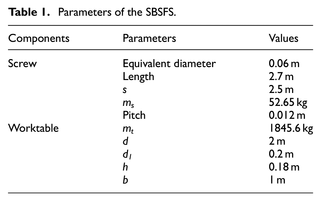
The SBSFS of a vertical five-axis machining center is shown in Figure 1(a). The feed system is mainly composed of linear guides, worktable, screw, coupling, and motor. The screw is attached to the motor shaft through a coupling and constrained by thrust bearings at two ends. The worktable is connected to the screw through a nut, and the worktable is connected to two linear guides through four sliders. The main structural parameters of the SBSFS are shown in Table 1.
Parameters of the SBSFS.
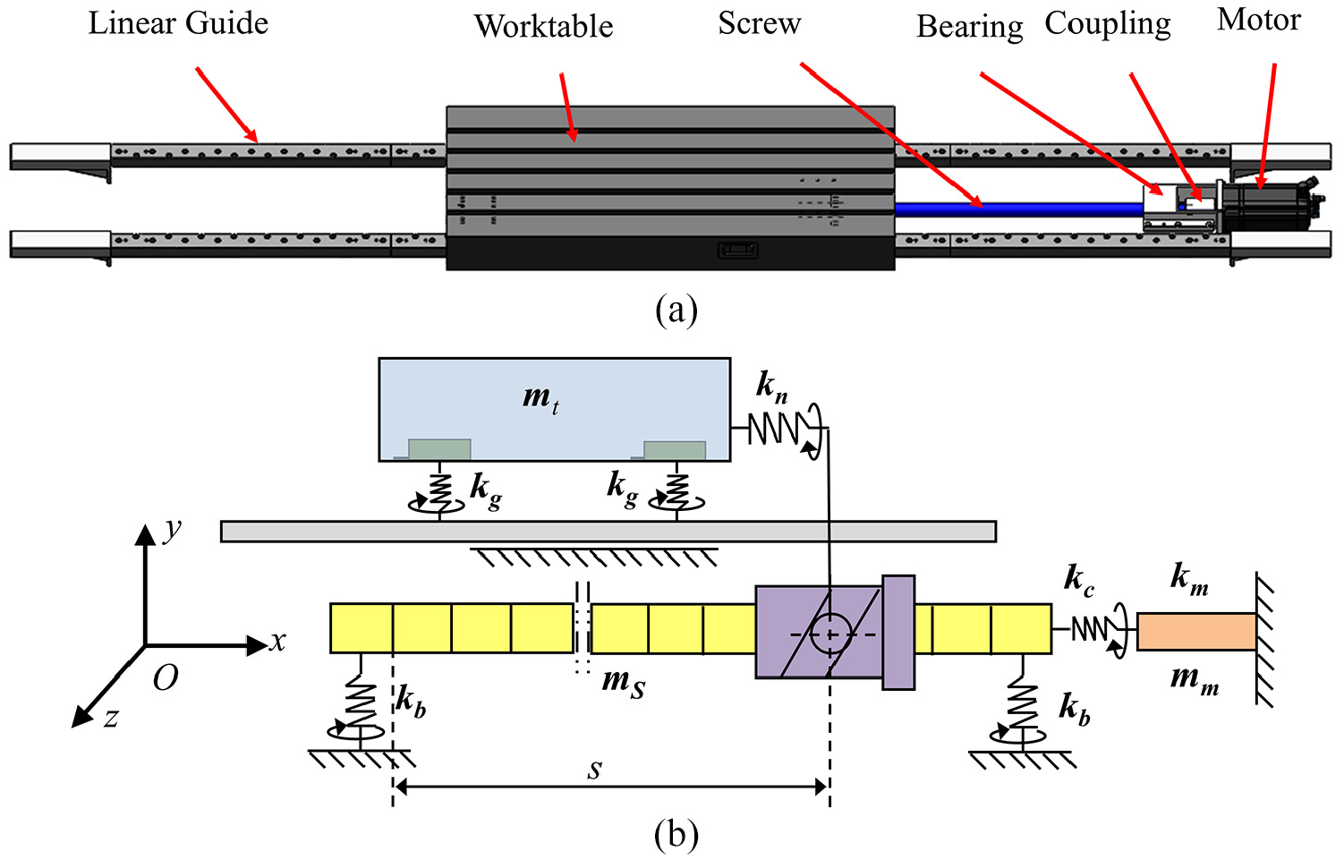
The slender ball screw feed system: (a) physical prototype and (b) equivalent dynamic model.
The interface of the kinematic joint is equivalent to a spring damping element for the SBSFS in the global coordinate system O-xyz, and there are three-dimensional linear stiffness and three-dimensional angular stiffness in each spring unit. The research mainly focuses on the mechanical structure, simplifies the motor as concentrated mass, and only involves the axial angular stiffness of the output shaft. Moreover, because the mass and volume are much larger than the lead screw, the worktable is dealt with a rigid body, while the screw is characterized by Timoshenko beam elements considering the axial, torsional, and lateral deformation. The equivalent model of the SBSFS is shown in Figure 1(b).
Dynamic model of motor substructure
The dynamic equation of the motor substructure can be expressed as follows

where
The displacement of the motor substructure is
where
where
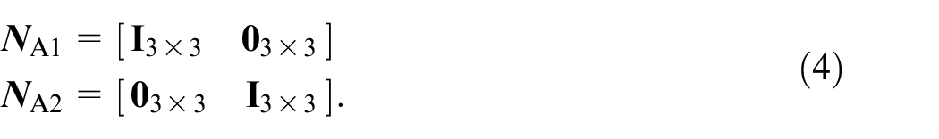
The force
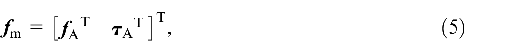
where
Dynamic model of screw substructure
The screw substructure is composed of the screw, nut, and supporting bearing at both ends. To consider the compliance of the screw, the screw is divided into n segments Timoshenko beams elements. There are two nodes in each segment, and there are three translational DOFs and three rotational DOFs for each node, as shown in Figure 2.
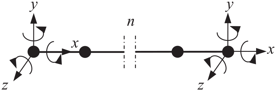
Screw based on Timoshenko Beam elements.
The dynamic equation can be written as

where
The screw is divided into n segments, and the displacement vector can be expressed by
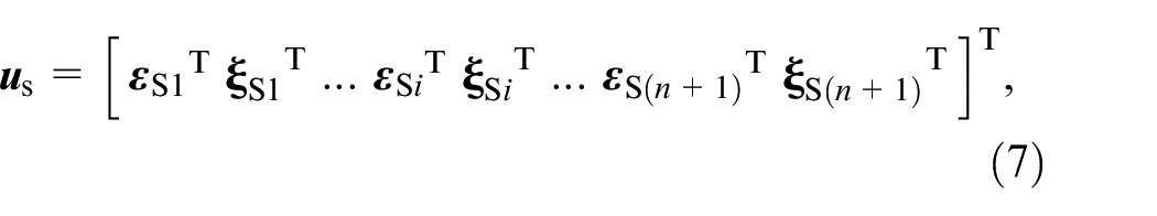
where
where
The joint force of the screw is expressed by
where
Dynamic model of worktable substructure
As shown in Figure, the worktable is regarded as a rigid body, with the mass concentrated in the geometric center. d and b denote the length and width of the worktable. The shortest distance between the nut and the end of the worktable is represented as d1. And h is the height difference between the screw geometric center and the worktable geometric center.
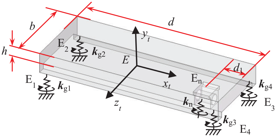
Equivalent dynamic model of the worktable.
The dynamic equation of the worktable is shown in equation (10).

where
The displacement vector
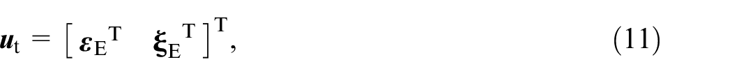
where
where
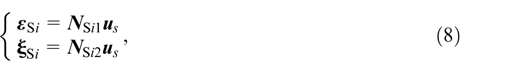
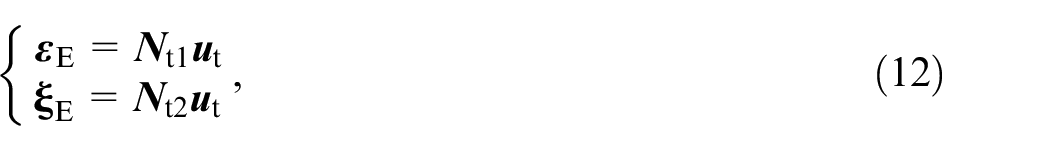
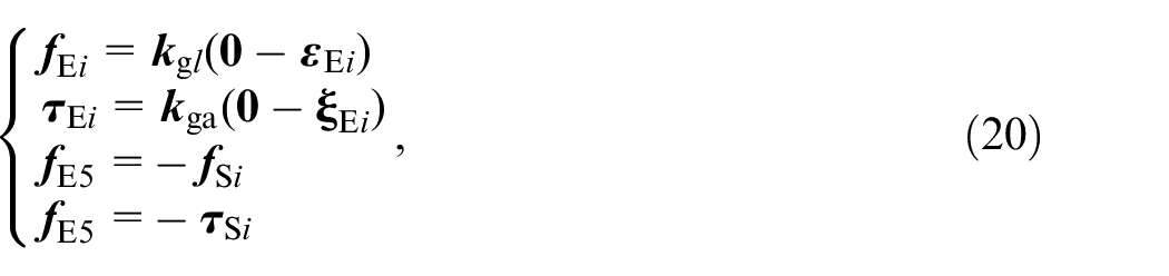
The elastic displacement of the E i can be expressed as
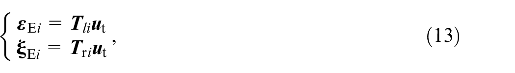
where
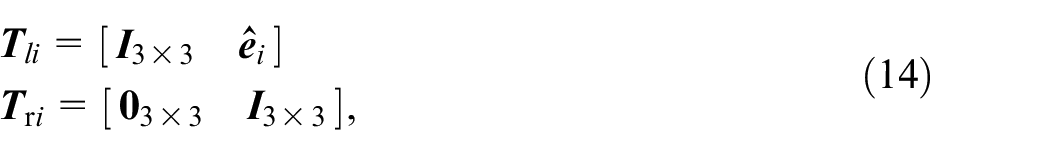
where
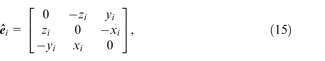
where xi, yi, and zi are the coordinates of the point Ei in the E-xtytzt
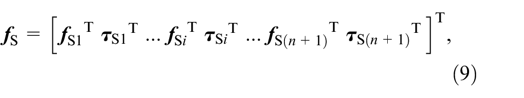
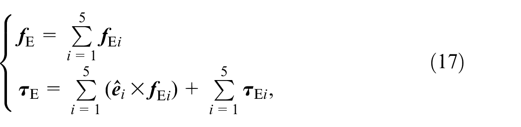
The external force applied on the worktable is expressed as follows

where
where
Compatibility condition
Displacement relations between the motor and screw, screw and supporting bearings, screw and nut, and linear guide and worktable are depicted in Figure 4, respectively.
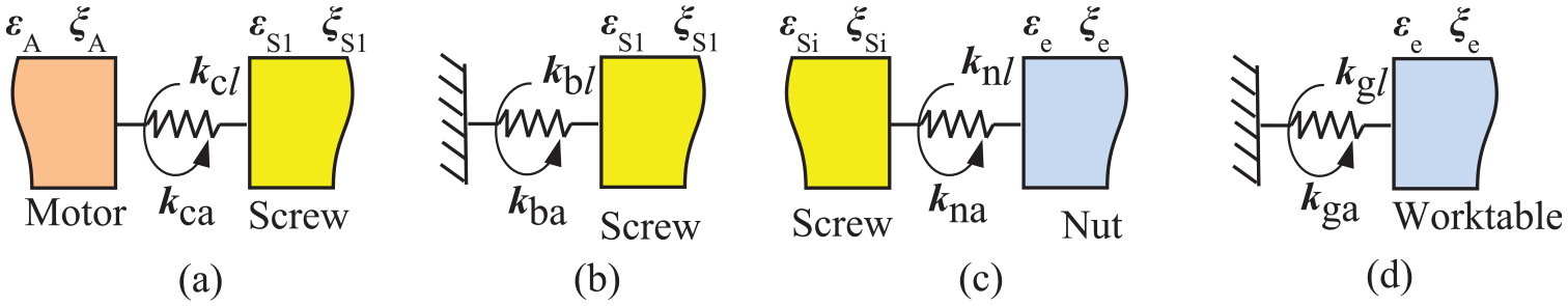
Displacement relationship: (a) motor and screw, (b) base and screw, (c) screw and nut, (d) base and worktable.
According to Figure 4,
where
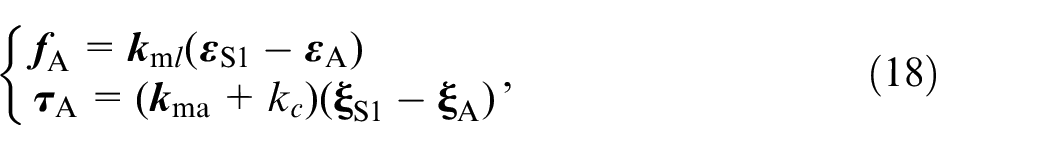
Reactions applied at the screw can be expressed as
where
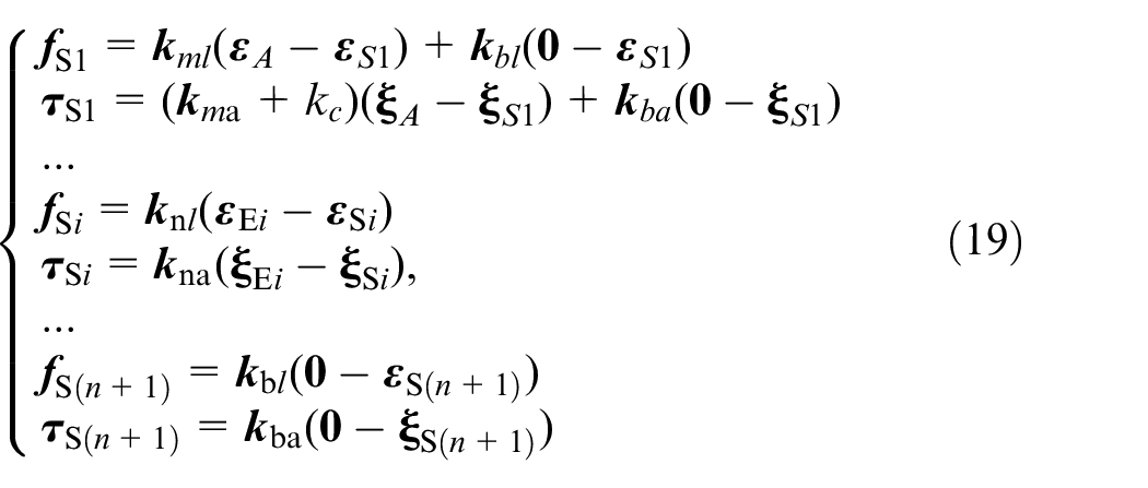
In addition,
where
Dynamic equation of the system
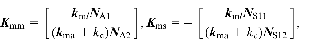
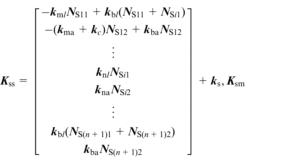
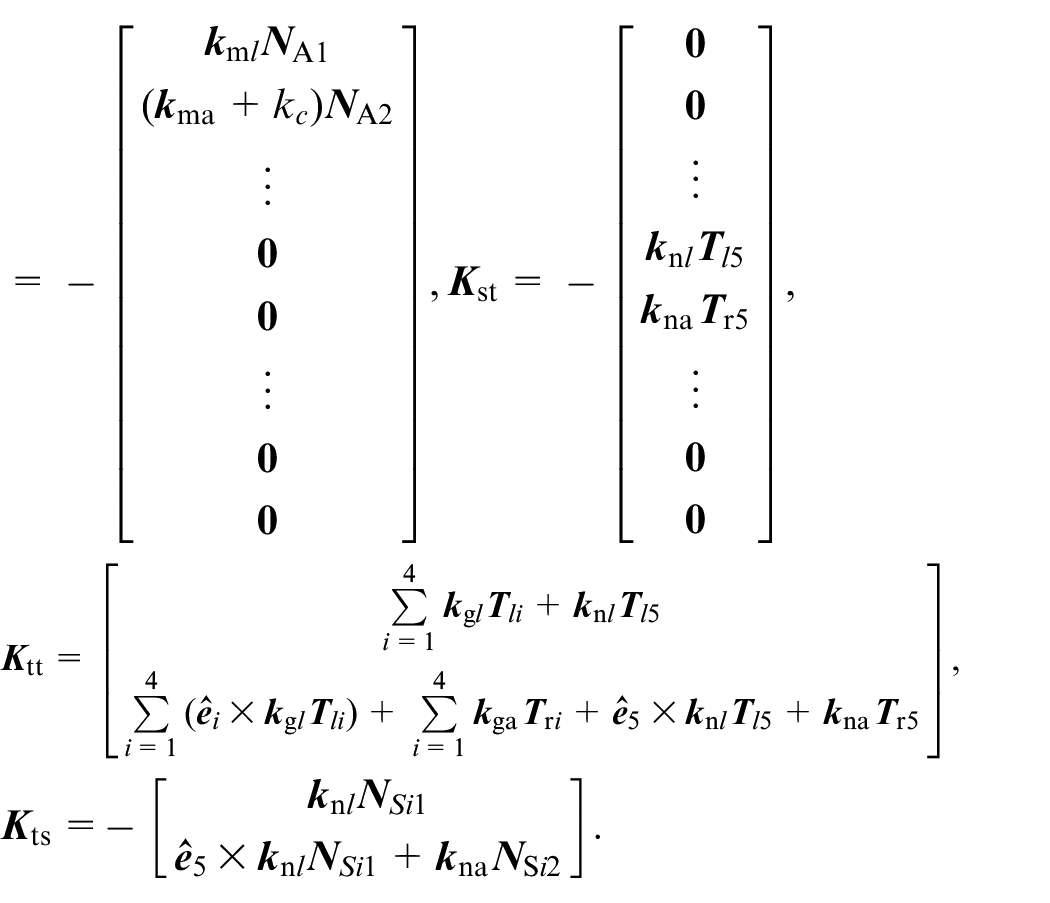
Substituting equations (18)–(20) into (1), (6), and (10) to derive the dynamic equation of the system

where
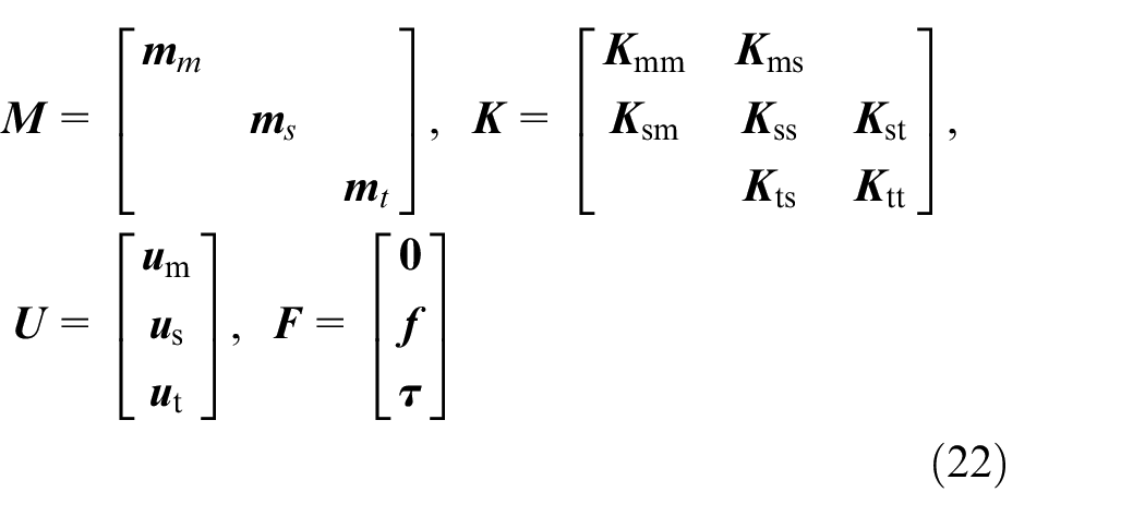
where
Dynamic characteristics analysis
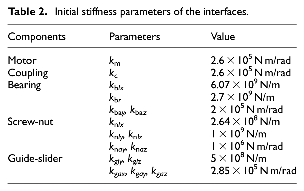
Based on the established dynamic model, the dynamic performance of the SBSFS is analyzed. The main structural parameters of the SBSFS are shown in Table 1. Initial values of the interfaces’ stiffness are shown in Table 2, which can be obtained variously from product catalogs and design handbooks from the manufacturer. Herein, km and kc are the angular stiffness about the x-axis of the motor shaft and coupling, respectively. kblx, kbly, and kblz are linear stiffness in the x, y, and z axes of the supporting bearing, respectively. kbay and kbaz are angular stiffness about the y and z axes of the supporting bearing, respectively. knlx, knly, and knlz are three linear stiffness in the x, y, and z axes, while knay and knaz are angular stiffness of the screw-nut interface about the y and z axes. kgly and kglz are linear stiffness in the y and z axes, while kgax, kgay, and kgaz are the angular stiffness of the guide-slider interface about the x, y, and z axes, respectively.
Initial stiffness parameters of the interfaces.
Based on these parameters, the first-order natural frequency of the SBSFS is calculated. Herein, the whole stroke of the worktable is from 0.1 to 2.5 m. As shown in Figure 6, when the worktable moves within the whole stroke, the first-order natural frequency increases firstly to a peak at 0.7 m, and then decreases to the trough at 1.4 m. When the table moves to both ends, the vibration characteristics of the system will change, and the first-order mode shape will evolve into the lateral elastic vibration of the screw. Therefore, only considering the axial DOF cannot truly reflect the first-order modes of the system. Especially in the process of high-speed machining, the vibration of the worktable will increase with the vibration of the screw, resulting in deterioration of dynamic error and the contouring error.
Verification of the proposed model
In order to validate the proposed model, experiments are conducted on the setup as shown in Figure 5. LMS Test. Lab is used to carry out the experiments by roving accelerometer mode. Considering the convenience of the experiments, four locations s = 0.6 m, s = 1.45 m, s = 2.1 m, and s = 2.5 m were selected for experimental research. The experimental results are shown in Figure 6. From Figure 6 it can be seen that the calculated values are found a good agreement with the experiment values, and the maximum error between the calculative and experimental of the first-order natural frequency is 12.91%. On the location s = 2.5 m, the mode of the SBSFS is the lateral vibration. Therefore, the accuracy of the proposed dynamic model is acceptable. Meanwhile, based on the constructed model, the first three-order natural frequencies are calculated as shown in Figure 7. The curve marked ABCD, ABFCD, and EBFCG represent the first-order natural frequency, second-order natural frequency, and third-order natural frequency of the SBSFS, respectively. Meanwhile, the curve marked EBCG represents the natural frequency of the axial vibration mode, while the curve marked ABFCD is the natural frequency of the lateral vibration mode. Combining Figures 6 and 7, the two peaks of the first-order natural frequency are the inflection point of the evolution between axial vibration mode and lateral vibration mode of the SBSFS. When the maximum of the ABFCD is bigger than the minimum of the EBCG, there are two peaks. While the maximum of the ABFCD is lower than the minimum of the EBCG, there will be only a single peak.
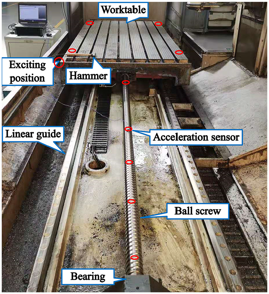
Experimental setup.
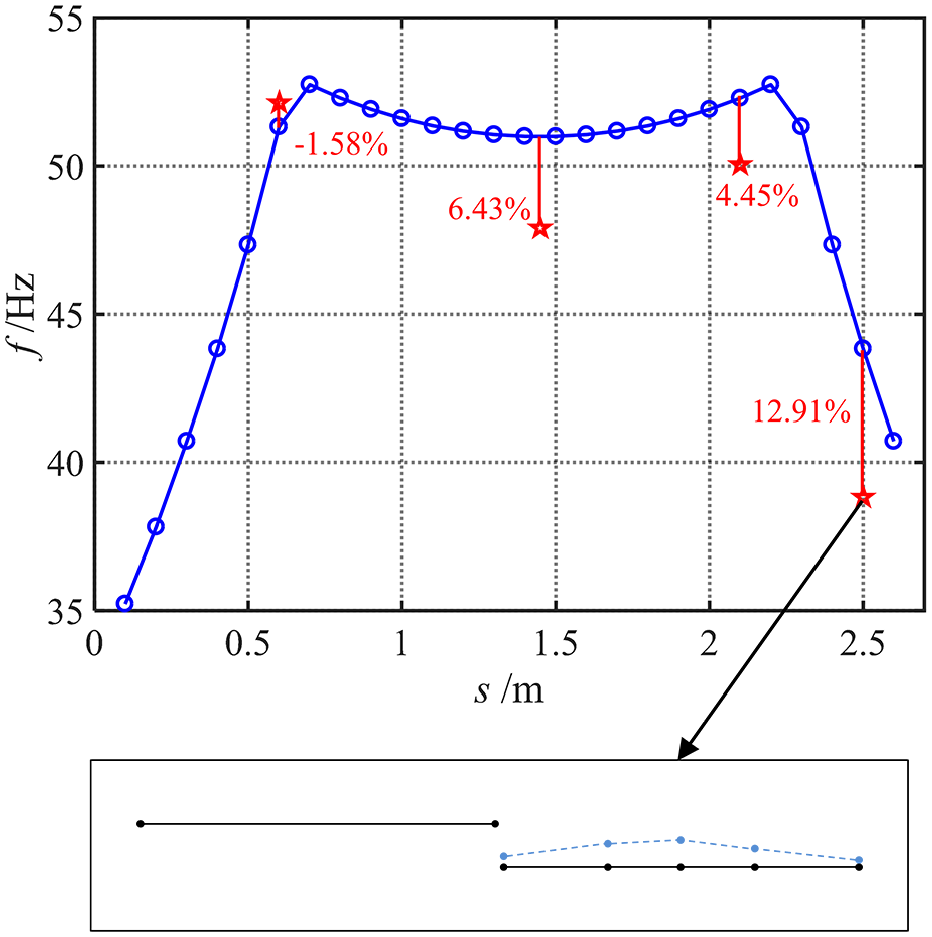
Comparison of experimental and analytic results.
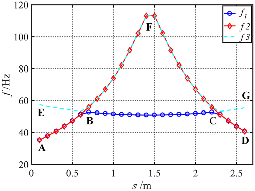
The first three-order natural frequencies.
In addition, it has been proven that tracking error mainly comes from dynamic error, and the dynamic error is significantly related to the dynamic characteristics of the system in high speed and high acceleration.1,3 Furthermore, variations of the first modal shape within the whole stroke will result in inconsistency of motion accuracy and machining accuracy, which is essential for machine tools. Thus, the first-order natural frequency of the SBSFS and vibration mode are critical to the performance of the machine tools in high speed and high acceleration.
Effects of joints’ stiffness on the vibration of the SBSFS
Based on the established dynamic model, the effects of joints’ stiffness on the first-order natural frequency and the evolution of the first-order vibration mode are mainly studied by the single factor method. The effects of the motor’s angular stiffness and the coupling’s angular stiffness on the first-order natural frequency of the SBSFS are shown in Figure 8. The results indicate that the first-order natural frequency increases gradually with the increment of the kc and km. Furthermore, the inflection points of the first natural frequency curve changes and moves toward the middle area. However, the first-order natural frequency will not change after rising to a specific value. Combined with Figure 7, kc and km mainly affect the natural frequency of axial vibration mode. The EBCG moves up with the increment of the kc and km. Thus, the two inflection points move to the middle area.
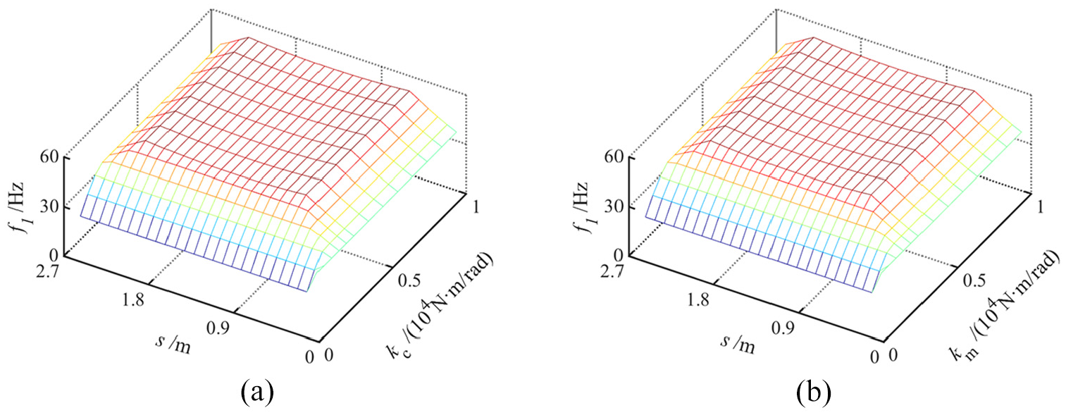
Effects of the stiffness of motor and coupling on the first-order natural frequency: (a) angular stiffness of motor and(b) angular stiffness of coupling.
The influences of the bearing’s stiffness on the first-order natural frequency of the SBSFS are shown in Figure 9. As can be seen from Figure 9(a), the kblx shows a significant influence on the first-order natural frequency. The first-order natural frequency in the middle area increases with the increment of the kblx, and the inflection points approach the middle area from both sides. As shown in Figure 9(b), the first-order natural frequency in both ends area increases with the increment of the kbly. However, it remains stable when it rises to a particular value, and the inflection point of the curve gradually moves to both ends. After reaching to 1.5 × 10⁷ N/m, the sensitivity of the first-order natural frequency to the kbly decreases. Figure 9(c) indicates that the kbay produces a considerable influence on the first-order natural frequency, however, as the kbay increases, the inflection point shifts to both ends. Combined with Figure 7, the kblx mainly affects the natural frequency of the axial vibration mode, while the kbly and kbay affect both the natural frequency of the lateral vibration mode. With the increment of the kblx, the EBCG moves up and the two inflection points move to the middle area. While, with the increment of the kbly and kbay, the ABFCD moves up and the two inflection points move to both ends.
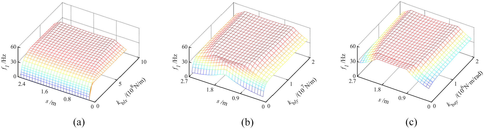
Effects of the bearing’s stiffness on the first-order natural frequency: (a) axial stiffness, (b) radial stiffness in y axis, and(c) angular stiffness.
Figure 10 shows the influences of the stiffness of the screw-nut interface on the first-order natural frequency. As can be seen from Figure 10(a), the first-order natural frequency corresponding to axial vibration gradually increases with the increment of the knlx, and the inflection points move to the middle area. At very low radial stiffness, Figure 10(b) shows that the first-order natural frequency slightly increases with the increment of the knly, while remaining unchanged when the knly increases to 1.5 × 10⁷ N/m. Meanwhile, the inflection points move to both ends. Compared with the knlx and knly, effects of the angular stiffness of the screw-nut interface are fairly tiny. Combined with Figure 7, the knlx and knly mainly affect the natural frequency of the axial vibration mode. So, the EBCD moves up and the inflection points move to the middle area with the increment of the knlx and knly.
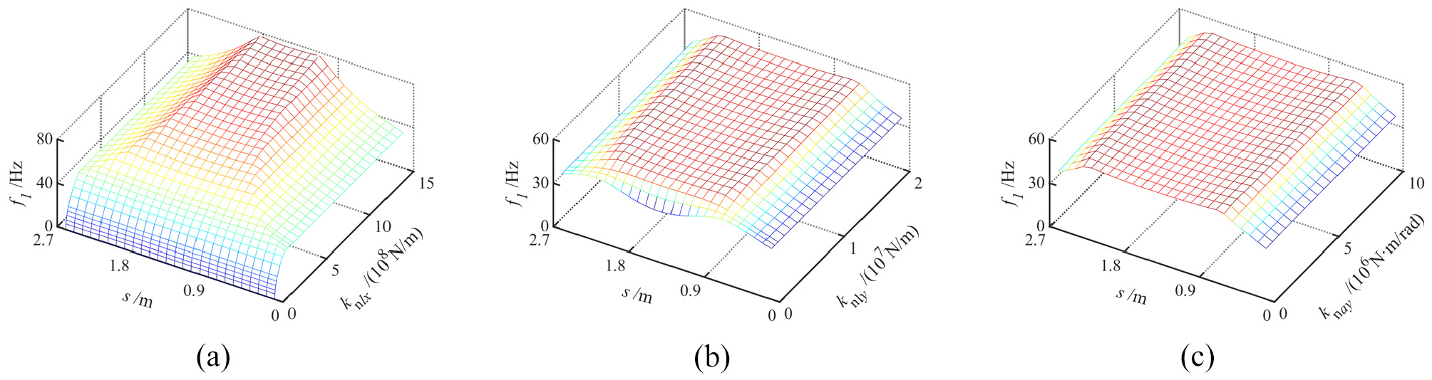
Effects of the stiffness of the screw-nut interface on the first-order natural frequency: (a) axial stiffness, (b) radial stiffness, and (c) angular stiffness about the z axis.
Figure 11 shows the influences of the guide-slider interface’s stiffness on the first-order natural frequency of the SBSFS. As can be seen in Figure 11(a), the first-order natural frequency corresponding to axial vibration increases with the increment of the kglz, and the inflection point moves to the middle area, but it remains unchanged when the stiffness increases to a specific value. Figure 11(b) indicates that the kgax leads to little influence on the first-order natural frequency. Combined with Figure 7, the kglz mainly affects the natural frequency of the axial vibration mode, so the EBCD moves up and the inflection points move to the middle area.
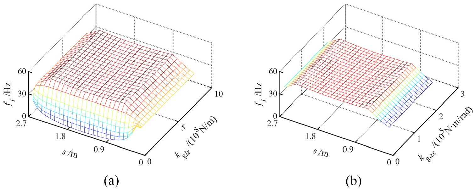
Effects of the stiffness of the guide-slider interface on the first-order natural frequency: (a) linear stiffness in the z axis and (b) angular stiffness about the x axis.
From the above discussion, the stiffness of kinematic joints shows important impacts on the first-order natural frequency of the SBSFS, among which the stiffness of the bearing and the axial stiffness of the screw-nut bring out a great impact on the system’s dynamic behaviors. Moreover, the evolution of first-order vibration mode of SBSFS is affected by the coupling between the linear stiffness and the angular stiffness. Therefore, there is limited in the dynamic model which only considers the axial stiffness of joints on reflecting the actual dynamic of the system, and the coupling between the linear stiffness and the angular stiffness should be considered.
Dynamic index of the SBSFS
From the view of machining, we attempt to maximize the middle area where the first-order natural frequency almost keeps unchanged with a relatively large value. Meanwhile, compared with lateral vibration, axial vibration is easier to control and compensate for the feed system. Figures 7 to 10 show that the middle area of the first-order natural frequency can be maximized through the matching optimization of the linear stiffness and angular stiffness of the joints. If only the axial stiffness of the screw-nut or bearing is increased, the natural frequency of the axial vibration mode of the SBSFS increases with the natural frequency of the lateral vibration mode remaining invariant. Thus the first-order natural frequency’s inflection points move to the middle area. If only the angular stiffness of the bearing is increased, the natural frequency of the axial vibration mode remains unchanged, and the inflection points of the first-order natural frequency move to both ends. Therefore, this paper proposes an evaluation index RSP based on the inflection point position of the first-order natural frequency.
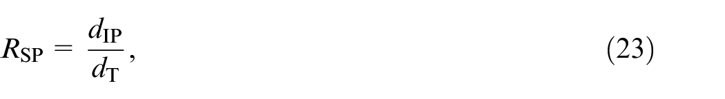
where dIP is the position corresponded to the inflection point, and dT is the distance between two support points of the screw, as shown in Figure 12.
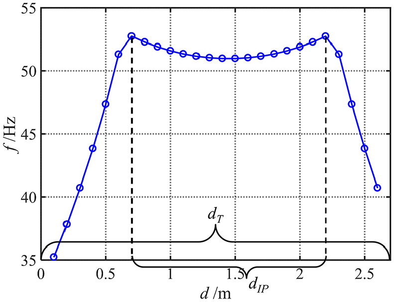
The dIP of the screw.
Therefore, RSP∈ (0, 1), and the smaller the value of RSP leads to the smaller ratio of the modal shape of the axial vibration mode within the whole stroke.
Taking the initial stiffness values of the SBSFS as an example, the RSP can be obtained.
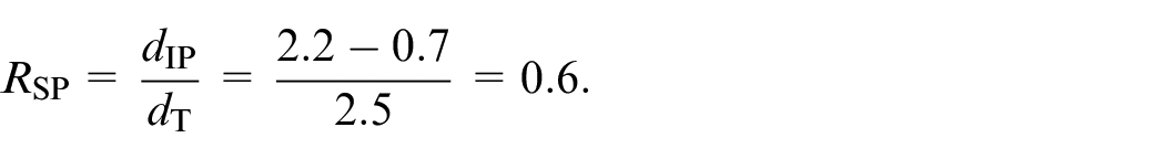
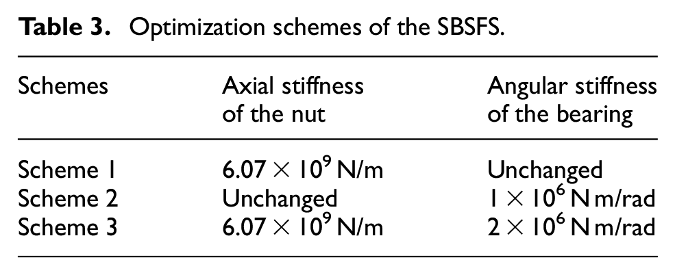
It indicates the stroke that the first-order modal shape is axial vibration accounts for 60% in the whole stroke. On the basis of the analysis in section 3.3, the axial stiffness of the screw-nut and the angular stiffness of the bearing are utilized to propose three optimization schemes to improve the dynamic performance of the SBSFS, as shown in Table 3. Hereby, the axial stiffness of the nut can be increased by preload of the nut, while the angular stiffness of the bearing can be changed by adjusting the supporting distance of the two bearings installed back to back.
Optimization schemes of the SBSFS.
The first-order natural frequencies of the three optimization schemes are calculated, as shown in Figure 13. The first-order natural frequency of the inflection point of scheme 1, Scheme 2, and Scheme 3 are 63.76, 53.27, and 59.79 Hz, respectively, and all of which are improved from the original 52.69 Hz. It can be seen from Figure 13(a), when the axial stiffness of the screw-nut increases and the angular stiffness of the bearing do not change, the natural frequencies of the axial mode increase, while the natural frequencies of the lateral mode remain unchanged. For scheme 2 as shown in Figure 13(b), the increase is significantly greater in the natural frequencies of the lateral mode with the increase of the angular stiffness of the bearing. In Figure 13(c), the natural frequencies of the axial mode and the lateral mode are all increased with the increase of the axial stiffness of the screw-nut and the angular stiffness of the bearing.
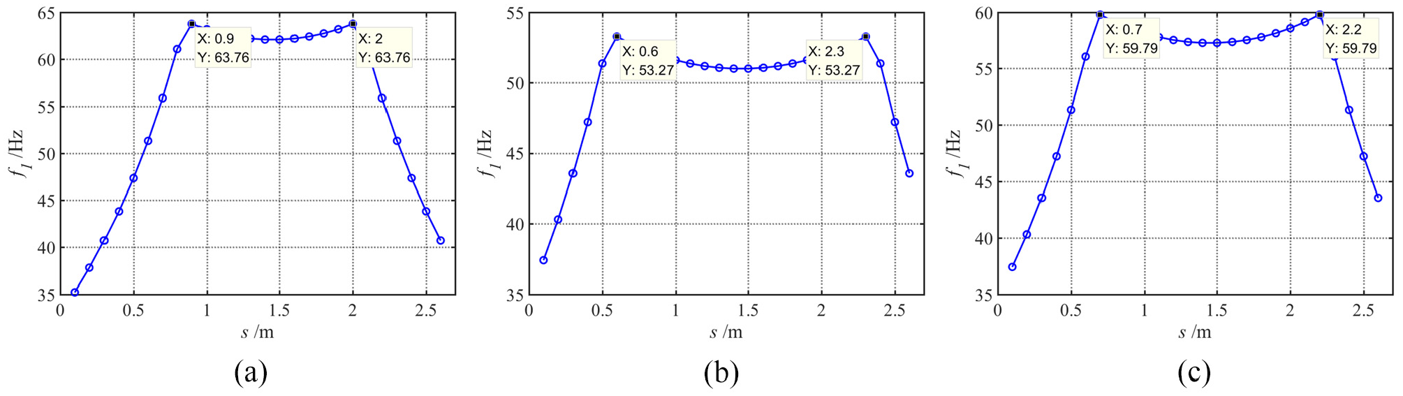
The first-order natural frequency of the three optimization schemes: (a) scheme 1, (b) scheme 2, and (c) scheme 3.
The three RSP values can be calculated as follows.

It is obvious that RSP of scheme 2 is the largest. However, the first-order natural frequency of scheme 3 is greater than that of scheme 2. According to RSP, scheme 2 is optimal, while scheme 3 is optimal when the first natural frequency value is taken into account simultaneously. To achieve comprehensive dynamic performance, the RSP and the first-order natural frequency should be considered simultaneously in the design of the SBSFS.
In the actual machining process, the middle section of the whole stroke is often chosen as the optimal working area. Especially for the SBSFS, facing the large-scale machined workpiece, the consistency of dynamic properties of the system in machining stroke is very important to ensure machining accuracy. As analyzed above, RSP determines the optimal working stroke of the SBSFS, and RSP is corresponding with the utilization factor of the screw. Furthermore, RSP, which is the ratio of the distance between inflection points and the distance between the support points, determines which lower between lateral vibration mode and the axial vibration mode. The RSP provides a novel method to evaluate the dynamic performance of the SBSFS, which is practical and convenient for the design and optimization of large-scale machine tools especially under high speed and high acceleration.
Conclusions
In this paper, the dynamic behaviors of SBSFS are analyzed with focusing on the evolution of first-order vibration mode. The major conclusions and contributions of this paper can be summarized as follows.
Considering the kinematic joints’ stiffness and the flexibility of the screw in/about the axial, torsional, and lateral directions, an elastodynamic model with a 6 DOFs end-effector is proposed in the paper. Experimental results demonstrate that the proposed model can perform dynamic behaviors accurately and rapidly.
The first-order modal shape of the SBSFS changes from the lateral vibration to axial vibration when the worktable moves from the end to the middle. For the SBSFS, the first-order natural frequencies vary with the variation of the joints’ stiffness. Furthermore, the joints’ stiffness in each direction has different effects on the first-order natural frequencies. The linear stiffness of the screw-nut and the bearing mainly affects the axial vibration mode, while the angular stiffness of the bearing is dominant in the lateral vibration mode.
A dynamic index RSP, which can reflect the evolution between the lateral vibration and the axial vibration of the SBSFS, is proposed. Because coming from the inflection point of the evolution between axial vibration mode and lateral vibration mode of the SBSFS, RSP can be used to evaluate and optimize the dynamic characteristics of the SBSFS effectively.
There is of great significance that the evolution of low order lateral vibration and axial vibration of SBSFS to suppress the dynamic error. Accordingly, the first model shape of the screw must be considered when analyzing the dynamic error and contouring error of the precision machine tool. The effects of the vibration mode of the screw on the dynamic error and contouring error of the machine tool are nonlinear as like the friction of the kinematic joints, which should be considered in pro-compensation strategy for machine tools in the future.
Footnotes
Appendix
Declaration of conflicting interests
The author(s) declared no potential conflicts of interest with respect to the research, authorship, and/or publication of this article.
Funding
The author(s) disclosed receipt of the following financial support for the research, authorship, and/or publication of this article: This work was supported by National key research and development program of China (grant number: 2017YFE0111300) and the National Key Science and Technology Project (Grant no. 2017ZX04013001).