
Abstract
Nowadays, micro molds have been playing an increasing crucial part in social and industrial fields. As the industry develops, the wear resistance of the micro molds has become more and more important because of its effects on the service life and economic benefit. Improving the hardness of the micro molds was an alternative to enhance its wear resistance, which can be realized by the electrodeposition of Nickel cobalt silicon carbide (Ni–Co/SiC). In this paper, attempts were made to fabricate Ni–Co/SiC micro molds, where supergravity field was introduced to further better the microhardness of the micro molds. The effects of supergravity field on the SiC content, morphology and microhardness of the Ni–Co/SiC micro mold were experimentally investigated. It was demonstrated that under gravity field, grain size is refined, and both the microhardness and morphology were dramatically improved. Finally, Ni–Co/SiC micro-pit molds were successfully obtained using optimized parameters. Production of Ni–Co/SiC micro molds with enhanced microhardness is feasible via electrodeposition under supergravity field.
Introduction
Micro Electro Mechanical System consisted of micro components has been increasingly applied in many fields such as, aerospace, automobile, biomedical device, and so on, which drives the soaring demand for micro components. Many technologies, for example, UV-LIGA, laser machining, electrical discharge micromachining, and electrochemical micromachining, have been carved out to produce the desired products,1–5 which are not efficient enough to catch up with market needs. Moreover, the market requires such products meeting the environmental requirements for sustainability.6,7 Therefore, innovations in appliance methods and materials need to be adopted to meet the product manufacturing cycle requirements, and micro molds are proposed to realize the mass production of micro components, which own the advantages of high machining precision and good uniformity. In order to fabricate micro molds, much attention has been paid to the development of the fabrication of micro molds. Abrasive water jet machining was successfully used by Azarsa et al. 8 to produce microfluidic molds with free-standing structures in Al6061 and SS316. Yu et al. 9 took advantage of micro electrical discharge machining to prepare micro punching molds with a punching clearance around 11 μm. A micro mold of gear was developed based on vacuum casting, and its functionality together with reproducibility was proved by Tang et al. 10
With the rapid development of society and industry, the durability of the micro molds has become more and more important because it influences the service life, production efficiency, and product quality, resulting in the decreasing economic benefit. Improving the microhardness of the micro molds is an alternative that extends the durability of the micro molds, which can be realized by altering material compositions and processing technologies. Electrodeposition is a method to fabricate micro components comprised of various material compositions. It features high dimensional precision, ease of reproducing complex structures, and convenience of mass production, 11 and has been widely used as an easy and cost-effective technique.12–17 Numerous researchers have utilized the method to prepare alloy coatings or composite coatings to enhance the performance of desired components.18–20 Cheng demonstrated the mechanical performance of micro Ni-Fe molds produced by electrodeposition is better than those of the counterparts formed by casting or powder metallurgy. 21
It has been reported that the supergravity field is helpful for electrodeposition and has been applied in this field due to some favorable advantages. 22 Eftekhai 23 enhanced the target properties of soft magnetic materials by using an external centrifugal force in electrodeposition. The mechanical properties of nickel foils were significantly strengthened via a supergravity field assisted electrodeposition, 24 and our previous research revealed that the addition of silicon carbide (SiC) nano particles to the Ni-Co matrix was able to substantially improve the wear resistance and microhardness of the as-prepared composite coatings. 25 In present paper, attempts were made to obtain Ni-Co/SiC micro molds via electrodeposition under supergravity field, which was expected to have an extended service life. To the best of our knowledge, there are no reports about the fabrication of micro molds with supergravity field assisted electrodeposition. The surface morphology, SiC content, microhardness of the micro molds were investigated systematically, and machining parameters were optimized. Finally, micro-pit molds with excellent performance were obtained.
Experimental
The set-up used in the experiments was depicted in Figure 1, which was composed of a supply power, a motor, a magnetic pump, a filter, an electrolyte tank, a temperature control unit, and a fixture. The supply power provided the energy needed for the experiments. The motor was used to provide supergravity field that could be adjusted through rotation speed, in which the fixture was connected to the motor firmly and rotated with the motor synchronously. The electrolyte was pumped into the working area by the magnetic pump, and the filter was employed to keep the electrolyte clean throughout the entire experiments. For the purpose of keeping the electrolyte temperature at 45°C ± 1°C, the temperature control unit was utilized to monitor its temperature in real-time. Pure nickel and a 304 stainless steel were used as anode and substrate, respectively.
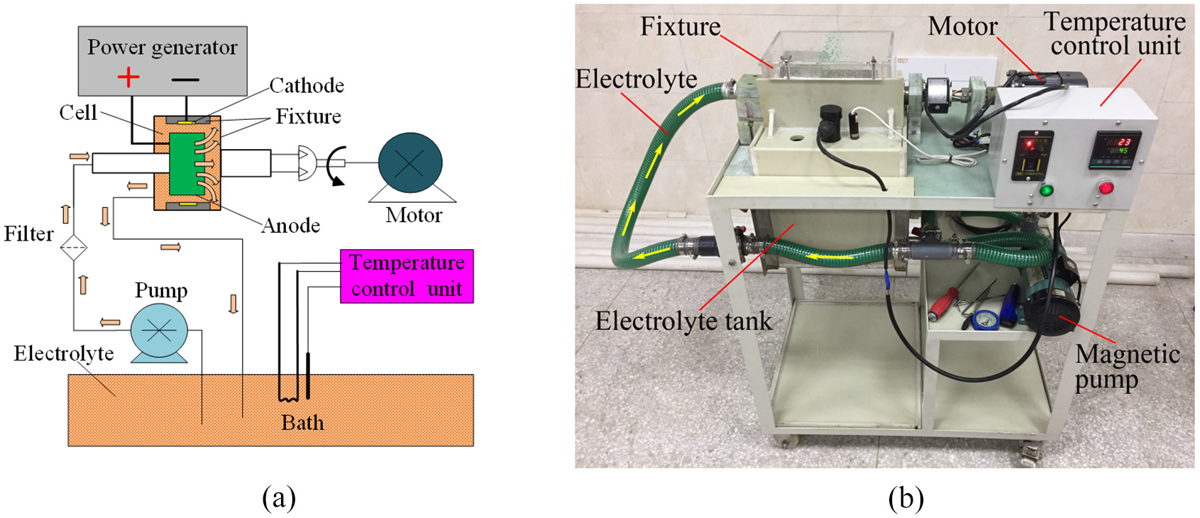
The experimental set-up using a supergravity field: (a) the schematic diagraph and (b) the real photo.
The composition of the electrolyte and machining parameters was listed in Table 1. Prior to experiments, the electrolyte was stirred for 2 h to disperse all components. The SiC nanoparticles were 40 nm in diameter, and the interelectrode gap was kept at 2 mm.
Electrolyte composition and machining parameters.
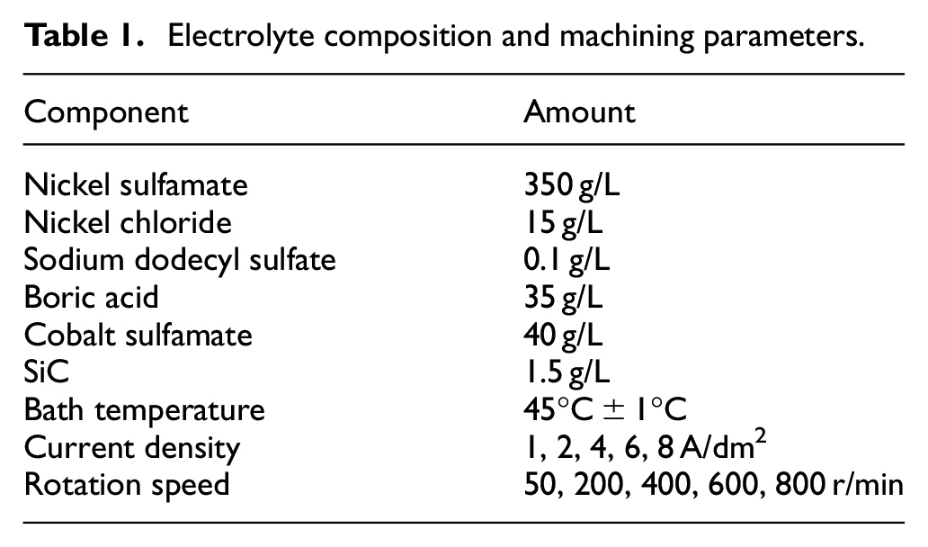
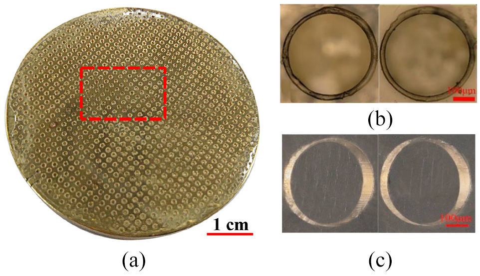
A GPM220 dry-film photoresist and a circular stainless steel plate comprised the master, where micro holes of 300 μm in diameter machined by photolithography covered the whole surface of the dry-film photoresist, as illustrated in Figure 2. The fixture mainly consisted of a hollow cylinder and a cover, as shown in Figure 3. A through hole that matched the cover existed on the surface of the cylinder. The master was inserted into the hole and tightly mounted by the cover, and the hole was well sealed to expose the working areas only. During experiments, the anode keeps stationary. After experiments, the workpiece was soaked in a solution of NaNO3 concentration of 2 wt.% for 8 min to get rid of the photoresist.
The master for the micro mold: (a) the full view, (b) the front view, and (c) the axonometric view of the micro holes.
Details of the fixture: (a) the oblique axonometric drawing, (b) the sectional drawing, and (c) the real photo.
Before tests, samples machined were removed from the substrate, and rinsed ultrasonically in acetone and deionized water, respectively. Subsequently, morphology was observed via scanning electron microscopy (SEM) using an S-3400N (Hitachi, Japan) system. SiC content was measured by energy-dispersive X-ray spectroscopy (EDS) embedded in the scanning electron microscope. Prior to microhardness tests, the samples obtained were embedded firmly on flat 304SS plates by acrylic, and a microhardness instrument (HXS–1000A, Shanghai Shangguang Instrument Plant, China) was used to test the hardness. The applied load was 50 g and lasted for 10 s. For each single mold, the average of the five measured values was used as the microhardness of the samples. The surface roughness of the coatings was examined with a three-dimensional optical profiler (S-neox 3D Optical Profiler). The preferred orientation of the coatings was examined by an X-ray diffractometer (XRD, X’TRA, ARL, Switzerland). Coating adhesion was measured by the friction method with a scratch instrument (WS-2005, Zhongke Kaihua Instruments Co., Lanzhou), in which samples with flat surfaces instead of micro molds were used for the convenience of testing. The experimental parameters were: applied load of 35 N, the scratch length of 4 mm, the length of the dead load of 2 mm, the reciprocation frequency of 1, and static pressure time of 30 s.
Results and discussion
The morphology and roughness
With the current density of 1 A/dm2, the influences of the rotation speed on the morphology were shown in Figure 4. It can be seen that the upper surface of the micro cylinder obtained without rotation was rather rough, and that the counterparts achieved with supergravity field were superior. At low rotation speed, the surface of the micro cylinder was relatively rough, and when the rotation speed increased beyond 400 r/min, voids existed on the side surface of the micro cylinder, as indicated by the red boxes in Figure 4(e) and (f). As the rotation speed was 400 r/min, the surface of the micro cylinder was smooth and no cavities were observed. According to the work, 26 within a certain range, the supergravity field can effectively refine the crystal grains and make the particles evenly distributed, which was reflected in Figure 4(g) and (h). Therefore, with the rotation speed increasing, the surface of the micro cylinder gradually became smooth. As rotation speed exceeded 800 r/min, the centrifugal force made it difficult for the bubbles to escape from the surface of the deposition layer, leading to the generation of voids.
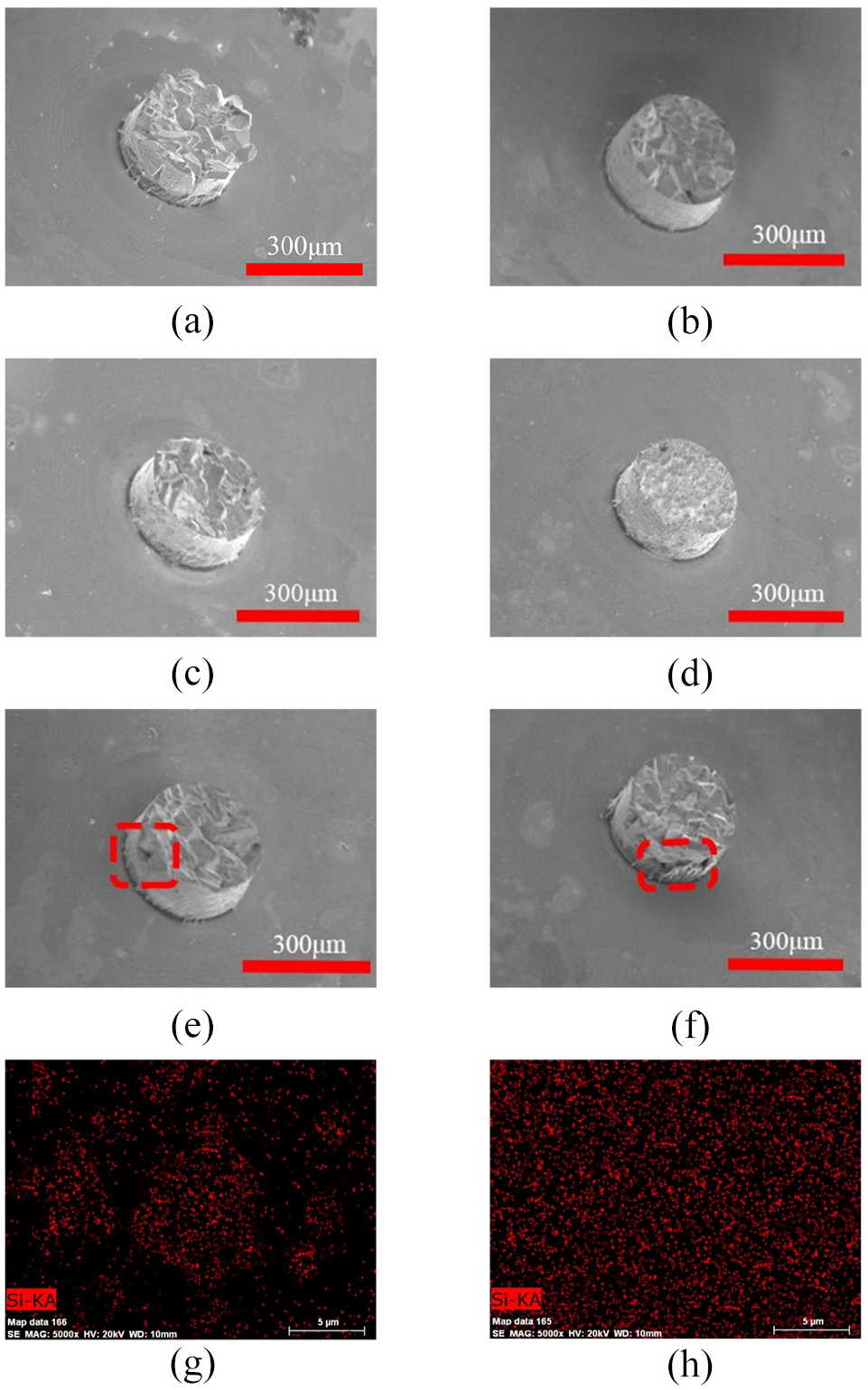
The effects of the rotation speed on the morphology: (a) 0, (b) 50 r/min, (c) 200 r/min, (d) 400 r/min, (e) 600 r/min, (f) 800 r/min, (g) mapping image for Si distribution of (e), and (h) mapping image for Si distribution of (d).
Using rotation speed of 400 r/min, the effects of current density on the morphology were presented in Figure 5. It was obvious that as the current density increased from 1 to 4 A/dm2, the top surface of the micro cylinder changed from rough to smooth. With the current density rising from 4 to 6 A/dm2, the top surface of the micro cylinder deteriorated again. When the current density is 4 A/dm2, the top surface of the micro cylinder was the smoothest. According to Guglielmi’s theory, 27 the formation of the deposition layer needed two steps. First, the particles were loosely adsorbed on the surface of the cathode because of the electrophoretic force and liquid flow. During the electroforming process, Co2+ and Ni2+ were adsorbed on the surface of the SiC nanoparticles, so they were positively charged, which facilitated the movement of SiC to the cathode under the action of electrostatic force. Afterward, the Co2+ and Ni2+ adsorbed on the surface of the SiC were reduced, while SiC nanoparticles were firmly embedded in the deposited layer. During the deposition process, the increasing current density resulted in the growing electrophoretic force, which attracted more SiC nanoparticles moving toward the cathode. The presence of SiC nanoparticles effectively increased the cathode polarization, provided nucleation points and inhibited the growth of crystal grains, giving rise to the smaller crystal grains. As a result, the surface of the micro cylinder became smooth with the current density increasing from 1 to 4 A/dm2. However, when the current density was above 4 A/dm2, the metal ions in the solution moved faster than the SiC nanoparticles, which meant that the metal ions were the first to deposit on the deposition layer. As the electrodeposition progressed, the proportion of SiC nanoparticles participating in the deposition declined, leading to the decreasing grain refinement effect brought by the SiC nanoparticles and the coarser crystal grains. Consequently, the surface of the micro cylinder became rough, as shown in Figure 5(d) and (e).
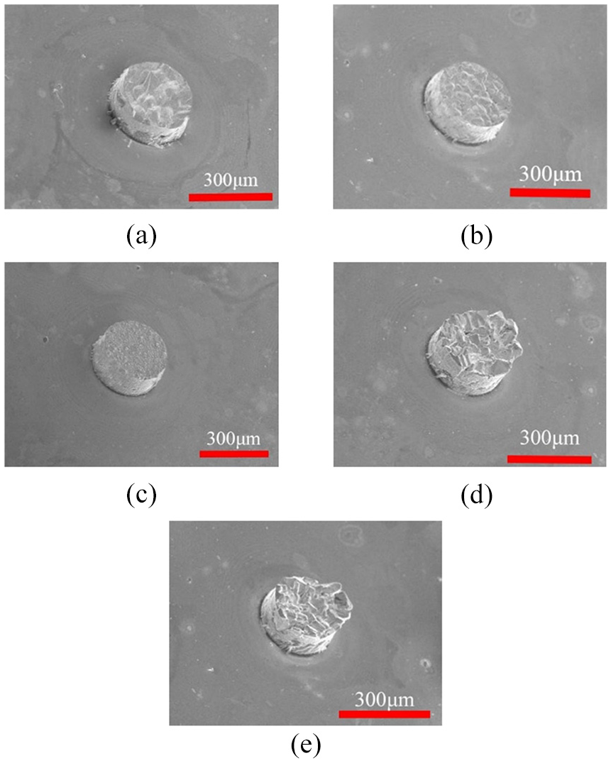
The effects of the current density on the morphology: (a) 1 A/dm2, (b) 2 A/dm2, (c) 4 A/dm2, (d) 6 A/dm2, and (e) 8 A/dm2.
As a consequence, the roughness of the coatings varied with the rotation speed and the current density, respectively. According to Figure 6, it is obvious that in both cases, the roughness of the prepared coatings decreased firstly and then rose. The lowest roughness value in terms of Figure 6(a) was obtained at the rotation speed of 400 r/min, which corresponded to Figure 4. In terms of Figure 6(b), superior surface roughness was achieved at the current density of 4 A/dm2, agreeing well with Figure 5.
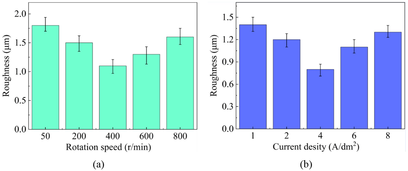
The effect of: (a) rotation speed and (b) current density on the surface roughness.
The SiC content
The influences of rotation speed on the SiC content were illustrated in Figure 7, from which it can be seen that with the speed of 50–400 r/min, the SiC content increased with the rotation speed. When the rotation speed exceeded 400 r/min, the SiC content declined sharply. Minimum SiC content of about 2.9 wt. % was observed with the rotation speed of 50 r/min, while the maximum SiC content of 7.6 wt. % was achieved using the rotation speed of 400 r/min. According to our previous work, 25 the resultant force of SiC pointed to the substrate with the low rotation speed, leading to the movement of SiC nanoparticles to the substrate; it faced the anode when the rotation speed was high, causing the SiC nanoparticles moving away from the substrate. Therefore, in the rotation speed range of 50–400 r/min, the rising SiC concentration near the cathode diffusion layer due to the SiC nanoparticles moving to the substrate enabled the SiC nanoparticles to be embedded in the deposited layer, thereby enhancing the SiC content. In addition, the presence of a supergravity field can improve the weak adsorption capacity of SiC nanoparticles, which was also helpful to improve the SiC content. In the case of rotation speed larger than 400 r/min, the declining SiC concentration near the cathode because of the SiC nano particles moving away from the substrate resulted in the reducing of the SiC content. Based on Guglielmi’s theory, SiC nanoparticles were first loosely adsorbed on the surface of the cathode, then moved closer to the surface of the cathode through electrophoresis, and finally embedded in the deposition layer as the metal ions are reduced under the action of Coulomb force. With rotation speed beyond 400 r/min, the flow rate of the solution near the cathode surface increased correspondingly, strengthening the erosion effect on the newly formed deposition layer and subsequently promoting the detachment of weakly adsorbed SiC nanoparticles from the cathode. Therefore, when the rotation speed rose more than 400 r/min, the SiC content decreased sharply.
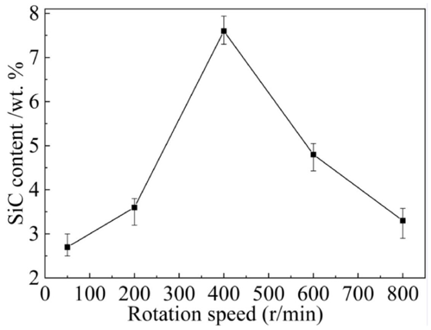
Effects of rotation speed on SiC content.
The influences of current density on the SiC content were shown in Figure 8. It can be seen that the SiC content grew first and then dropped rapidly before and after the current density of 4 A/dm2. SiC content reached its maximum at 4 A/dm2, which was about 9.3 wt. %. The trend was similar to Figure 4, and the reasons were the same as the effects of current density on morphology in section 3.1.
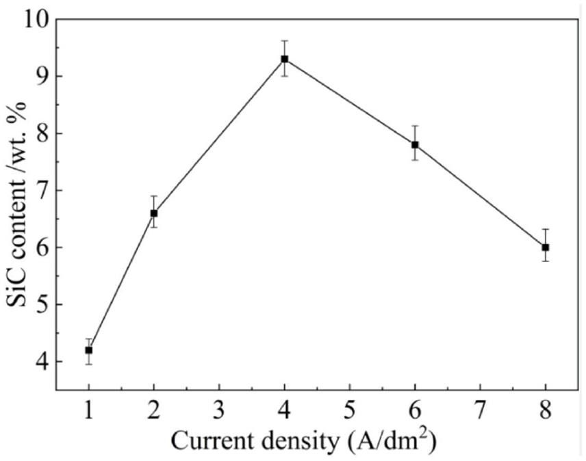
Effects of current density on SiC content.
The XRD analysis
The XRD analysis was performed on the micro molds corresponding to Figure 4, and the results were illustrated in Figure 9. It was clear that all the XRD data demonstrated the face-centered cubic structures of the micro molds. The diffraction peaks for SiC can be evidently observed only in Figure 9(c), which was presumably the reason that the SiC content in the Figure 9(a) to (e) was too low to be detected as revealed in Figure 7.
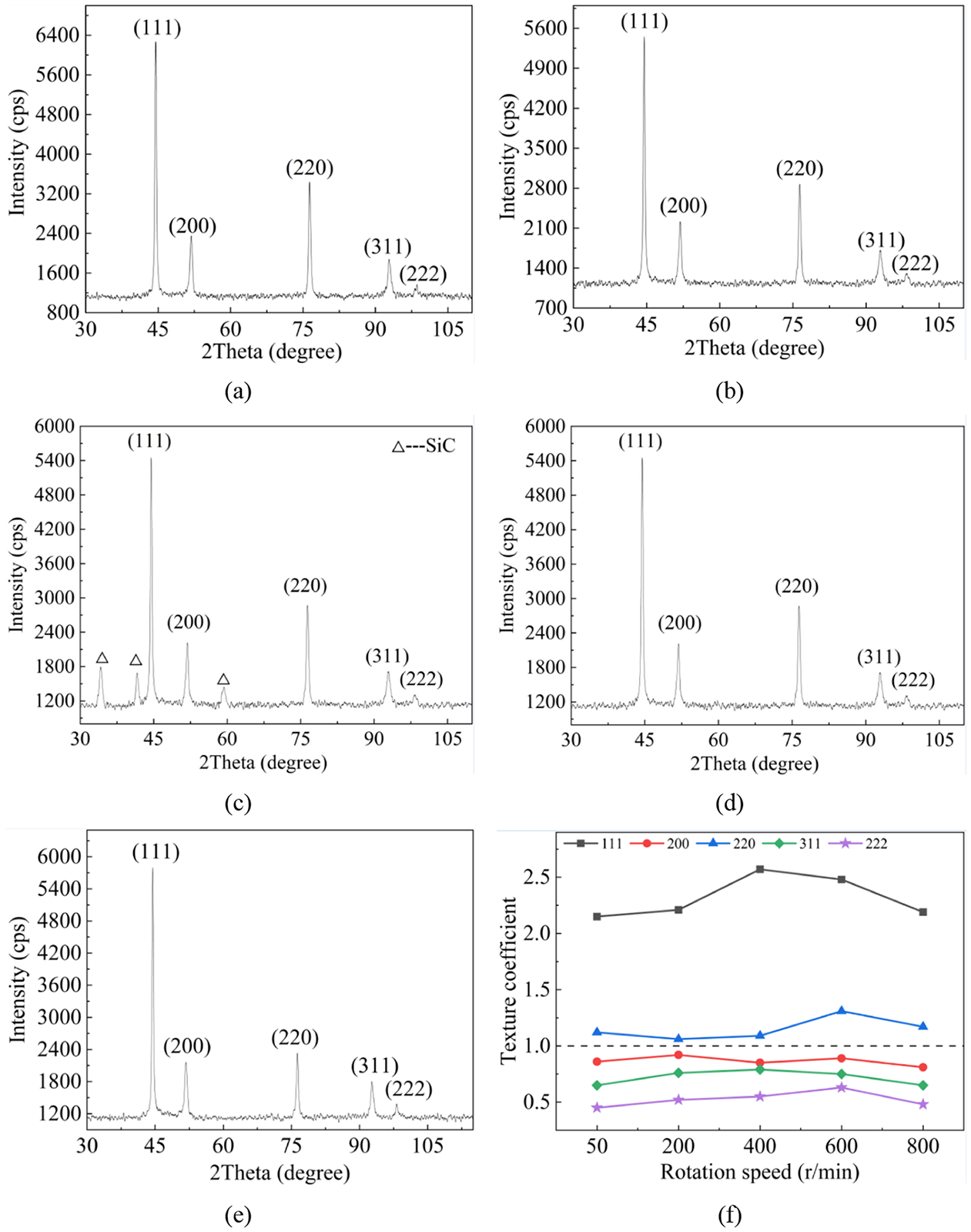
XRD patterns of micro molds with current density of: (a) 50 r/min, (b) 200 r/min, (c) 400 r/min, (d) 600 r/min, (e) 800 r/min, and (f) texture coefficient in terms of rotation speed.
Texture coefficient (TC) was obtained with equation (1), 28 which was used to evaluate the preferred crystal orientation. The TC results were shown in Figure 9(f).
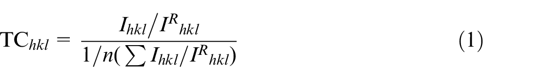
Where
Based on Figure 9(f), it is clear that the under supergravity field, TC values varied with the rotation speed and the TC values of the plane (111) and (220) were larger than 1 regardless of current density used herein, indicating their predominance. In comparison, TC values of the plane (200), (311), and (222) were below 1 for all conditions, which meant they were not preferred crystal orientation. In conclusion, rotation speed affected the intensity of plane orientation, but no shifts of preferred crystal orientation were observed.
According to the Scherrer equation 29 below, the grain size was calculated, and the results were illustrated in Figure 10.

where the FWHM denotes the full width half maxima (2θ°), D presents the grain size in nanometers, K is a constant (generally 0.94), and the wavelength of Cu Kα radiation is 0.154 nm.
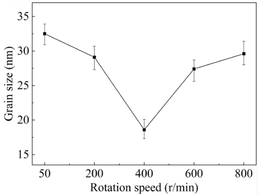
Grain size as a function of current density.
It was obvious that the grain size of the molds prepared at 50 r/min was the largest, approximately 32.5 nm. As the rotation speed rose from 50 to 400 r/min, the grain size reduced continuously and reached its minimum value of 18 nm at 400 r/min, while it increased drastically with the further increase of rotation speed. Grain size is closely related to both nucleation rate and the grain growth rate. A nucleation rate larger than the grain growth rate gives rise to a smaller grain size, while a prevailing grain growth rate contributes to a larger grain size. In the case of a supergravity field, the SiC concentration in the vicinity of the diffusion layer at the cathode surface was enhanced, which supplied more nucleation sites 27 and afterward led to a smaller grain size. In addition, SiC particles adhered on the cathode diminished the effective reaction area, lessening the reduction potential of matrix. 30 However, a further increase of rotation speed posed negative effects on the SiC concentration. 25 As a result, the grain size varied correspondingly, which was in good agreement with Figures 4 and 7.
The microhardness and coating adhesion
Figure 11(a) represented the effects of the rotation speed on the microhardness. The microhardness increased significantly as the rotation speed rose from 50 to 400 r/min, while it reduced sharply with the rotation speed of more than 400 r/min. Maximum microhardness of 620 HV was obtained at 400 r/min, and it was clear that the minimum one appeared at 50 r/min. According to Figure 7, the SiC content rose with the rotation speed within 50–400 r/min. On the one hand, the presence of SiC nanoparticle was helpful to refine the grains of the deposited layer, leading to an improved microhardness. 31 Besides, more boundaries were produced because of the refined grains, and were able to hinder the movement of dislocations, which substantially reduced the deformation of the deposited layer and contributed to the reinforcement of microhardness. 32 In addition, due to the SiC nanoparticle embedded in the deposited layer, the plastic deformation of the deposited layer led to a shrinkage effect because of the dispersion strengthening effect, greatly strengthening the microhardness of the deposited layer. 33 As a result, the microhardness increased as the rotation speed rose. However, when the rotation speed was larger than 400 r/min, the SiC content decreased dramatically, resulting the larger grains. Hence, the microhardness was significantly reduced. Moreover, reduced SiC content in the deposited layer weakened the dispersion strengthening effect, decreasing the microhardness. Consequently, the microhardness reduced with the rotation speed of higher than 400 r/min. Figure 11(b) demonstrated the trend of coating adhesion affected by rotation speed, from which it was distinct that the coating adhesion change altered in a similar way to the microhardness.
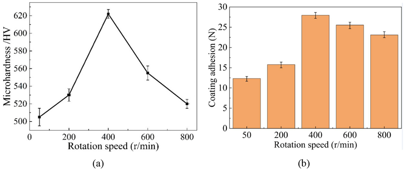
Effects of rotation speed on: (a) microhardness and (b) coating adhesion.
Figure 12(a) reflected the change of microhardness with current density. Apparently, when the current density is lower than 4 A/dm2, the microhardness increased firstly and then reduced before and after the current density of 4 A/dm2. Maximum microhardness of 640 HV was obtained at the current density of 4 A/dm2. The microhardness was improved by the strengthened dispersion effect due to the increasing SiC content within the current density of 1–4 A/dm2, and was deteriorated by the weakened dispersion effect because of the decreasing SiC content in the current density range of more than 4 A/dm2. Therefore, the microhardness was in positive relation to the current density in the range of 1–4 A/dm2, and otherwise in negative relation. Coating adhesion increased firstly and then dropped with current density, reaching its summit at the current density of 4 A/dm2, as displayed in Figure 12(b).
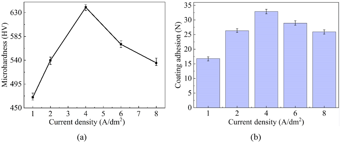
Effects of current density on: (a) microhardness and (b) coating adhesion.
Fabrication of micro pit mold
The optimal processing parameters obtained according to the processing results were: current density 4 A/dm2, rotation speed 400 r/min. These optimal parameters were used to process micro-pit mold with excellent morphology, as shown in Figure 13. Ni–Co/SiC nanocomposite micro-pit mold was successfully obtained by electrodeposition under supergravity field. It revealed that both the side and faces were smooth and that no evident flaws were observed. Figure 13(b) illustrated the prepared micro-pit mold is precisely repeated with distinct, sharp features.
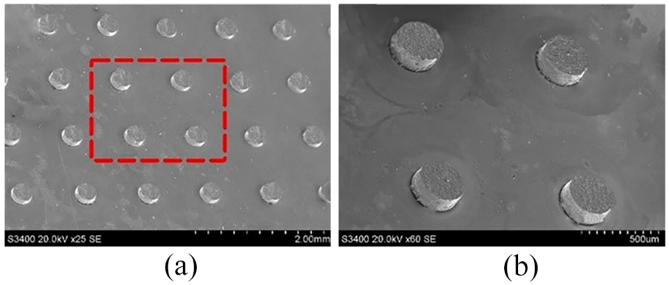
SEM images of: (a) the micro pit mold and (b) the close-up image of red marked region.
Conclusions
In this work, Ni-Co/SiC micro mold are prepared by electrodeposition under supergravity field and machining parameters were optimized. Based on the experimental results, the conclusions can be drawn as follows:
(1) Under the supergravity field, SiC content of the Ni-Co/SiC micro mold varied with the rotation speed and the current density. The maximum (7.6 wt. %) was achieved with a current density of 4 A/dm2 at the rotation speed of 400 r/min.
(2) SiC nanoparticles embedded in the Ni-Co/SiC micro mold helped refine the grains and effectively improved microhardness of the micro mold. Maximum microhardness obtained was 640 HV.
(3) Micro-pit mold with smooth surfaces and sharp features were successfully fabricated by electrodeposition under supergravity field.
Footnotes
Declaration of conflicting interests
The author(s) declared no potential conflicts of interest with respect to the research, authorship, and/or publication of this article.
Funding
The author(s) disclosed receipt of the following financial support for the research, authorship, and/or publication of this article: This work was supported by the National Natural Science Foundation of China (grant number 91860208) and the National Natural Science Foundation of China for Creative Research Groups (Grant number 51921003).