
Abstract
In spite of product quality increase in the cold roll forming process by previous practical researches for defects prevention, there are some ill-considered defects such as over-bending, which diminished the product quality in the open section products of this process. This defect which happens by superfluous bending of sheet in the forming stand not only lead to defective products, but also trigger other defects such as edge wrinkling. Since in an elaborate process such as cold roll forming, forming parameters play an active role in defect prevention, the effect of some important parameters is investigated on the over-bending defect and product bending angle by doing 68 experimental tests and numerical simulations in the present study. The list of parameters which are investigated includes bend angle increment, flange width, strip thickness, radius of bend, strength of the materials, and inter-distance between successive stands. In addition, the reason behind the effect of each parameter on the accuracy of the bending angle is laid out. Results show that over-bending defect can be compensated or even eliminated by decreasing the bending angle in each stand, a technique called bending angle increment. Increasing the number of forming stands from two to five causes the over-bending to decrease from 6° to 0°. With bending angle increment being the most impactful factor, bending radius, flange width, and strip thickness have a decreasing impact on over-bending. This study also brings forward a reverse relationship between the strength of the material and the intensity of over-bending. The inter-distance between successive stands was found to have the least effect on over-bending. Results highlight the importance of pre-form rolls at the beginning of the roll forming line. Without the usage of pre-form rolls, the folding of strips on a 60° angle, cannot be done in one stand.
Introduction
Roll forming is a highly efficient process to produce shapes with a constant section and desired length. The process consists of passing a strip through successive stands equipped with a pair of rotation rollers. By the end of the production line, the final shape is obtained. The uniformity of this forming process insures a low defect rate. 1 Nowadays, because of high production speeds, along with high geometrical accuracy, structural products are increasingly produced using a roll forming process. However, due to the multiple forming steps, control of the products’ geometry is complicated. 2 The most common defects that happen in the roll forming process are buckling, wrapping, edges wrinkling, and springback. There is a significant amount of research on potential solutions to these defects, tested via experimental and numerical methods. 3
Among the aforementioned geometrical defects, some studies have investigated springback. Groche et al. 4 studied the behavior of springback for different parameter combinations. The authors introduced a virtual calibration system that could compensate for springback occurring during the roll forming process. Liu et al. 5 studied roll forming of hat-shaped section, and implemented the relational springback analyses to compare with FEA simulation results. The results showed that springback increases with increasing flange width, sidewall height, roll gap, and increasing distance between the stands. The calculated accuracy of springback improved by 18% using Swift’s material model. Paralikas et al. 6 used the finite elements (FE) method to investigate the effect of the roll forming passes’ design on main redundant deformations, as well as predict the profiles’ springback in symmetrical V- and U-sections. They found that the flower pattern has a great impact on redundant deformation and springback. Badr et al. 7 presented an effective numerical approach to compensate for redundant defects. They proved its applicability through numerical roll forming and V-die bending studies, and verified its effects with experimental results. Their model was consistent with experimental results, and reproduced the minimized springback observed in roll forming, as compared to simple bending. This suggests that the lower level of springback observed in roll forming compared to V-die bending may be due to kinematic hardening effects. Li et al. 8 investigated the performance of AHSS in chain-die forming. They performed a systematic comparison between chain-die forming and roll forming of theU-channel based on the verified FE model. Their results showed that the chain-die forming causes more springback than roll forming. This implies more compensation is needed to obtain a desired product through chain-die forming. Zeng et al. 9 established a mathematical model that represented the effect of forming angle increment and roll radius on springback angle and maximum edge longitudinal membrane strain, respectively, using a response surface method. Their optimization process was performed with the springback angle as the objective function, to insure high forming accuracy, as well as a minimum of roll stands, to optimize efficiency. Abvabi et al. 10 studied the influence of residual stress and plastic deformation on the material behavior in roll forming. Results of their studies showed a reverse relationship between thickness reduction rolling, and bow height, on one hand – as thickness reduction I achieved through the rolling process, the maximal bow height decreases – and a positive relationship between thickness reduction rolling, and both the springback angle and the end flare, on the other hand – as the thickness is effectively reduced through the rolling process, the springback angle and end flare increase. Badr et al. 11 explored the potential use of different roll forming methods to reduce springback in the cold roll forming of Ti-6Al-4V sheets. Their experimental and numerical results indicated that the constant radius forming method leads to fewer shape defects and reduced springback in the process. Wang et al. 12 investigated the effect of the residual stress of the roll forming process on CFS sigma beams using numerical and experimental methods. Their results indicated that residual stress caused the decrease of the load-bearing capacity of the sigma beam. Rouholamin et al. 13 studied the shear behavior of aluminum lipped channel beams experimentally produced by cold roll forming. The test sections were subjected to load at mid-span at the shear center until fracture. Their results indicated that tests with web side plates on both sides had near 10% shear strength more than tests with one web side plate. Cheng et al. 14 did numerical tests using roll forming software COPRA as well as experimental tests to investigate the flexible roll forming of ERW pipes. The results showed that the distribution of transverse strain was optimized with the flexible design of the flower pattern. Sheu et al. 15 used a flexible roll forming machine to produce a U-section profile with concave and convex forming contour from high strength steel sheet. The numerical method was used to assess the forming process and die design. Their results indicated that the shifting phenomenon caused the geometry error, and this drawback should be controlled during the forming process. Safari and Joudaki 16 studied the bending angle of the machined blank using an artificial neural network. Their results showed that a 5 × 8 × 1 trained neural network could predict the experimental result with a 1.1% error in predicting bending angle.
Until now, over-bending had not been investigated, even though it is a remarkable defect, especially in high bend angle increments. In contrast to the V-bending and U-bending techniques, in which the whole length of the bending line is formed simultaneously, in the roll forming process, the bending is done progressively: the forming starts at the beginning of the bend line and continues to the end. Figure 1 shows the mechanism that causes over-bending. As seen in this figure, when considering a transversal line on the strip, one can witness that line reaching the forming rolls in point A first, point B second, and point C third, before reaching the bending point D. Therefore, prior to reaching point D, stretching and bending occurs on other regions of the line. When point A reaches the forming rolls, force F pushes the strip against the roll, which reacts against the strip movement such that the strip deflects and detaches from the roll. The same deformation mechanism happens for points B and C, albeit with less intensity.
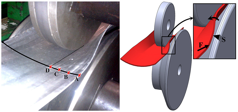
Occurrence of over-bending in cold roll forming process.
There are several rolling stands with different bending angle. This makes controlling the defect risk by changing parameters difficult, because some input parameters can interrupt the effect of others. Therefore, altering any parameter requires prior knowledge on its respective effect on the bending mechanism. In the present study, the behavior of over-bending is investigated, both experimentally and numerically, by changing input parameters such as bend angle increment, flange width, inter-distance between the successive stands, radius of bend, strip thickness, and material strength. Since there are different forming parameters in the cold roll forming process that can trigger or intensify the occurrence of the over-bending defect, it is vitally important to investigate the effect of process parameters on this defect. In spite of the accomplishment of a huge number of researches pertaining to cold roll forming defects, the over-bending drawback has not been investigated in the previous studies. Therefore, investigation of this defect in the cold roll forming process will be the main novelty of the present research.
Methodology
Properties of aimed product
This paper studies a common product, on which over-bending is easily noticed, called U-shape cross-section. The geometry of the product is shown in Figure 2.
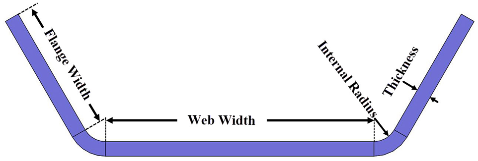
Schematic cross section of a roll formed channel.
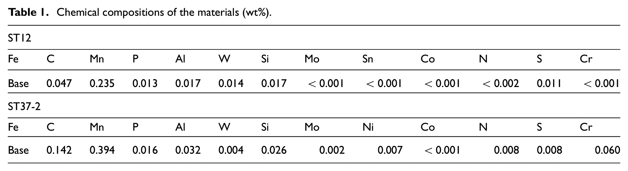
In this study, some of the geometrical features of the initial product, such as strip thickness, radius of corners, and flange width, were changed from a sample to another in order to analyze their effect on over-bending. Annealed Cold rolled ST12 and ST37-2 carbon steels (DIN Standard) were two types of materials used in this study. The chemical composition of the materials is provided in Table 1.
Chemical compositions of the materials (wt%).
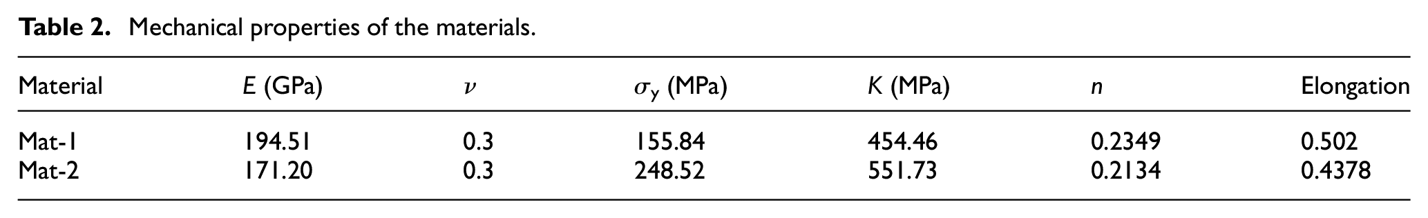
The mechanical properties of materials were measured using ASTM Standard. 17 Figure 3 and Table 2 show the stress strain diagram and the mechanical properties of the materials respectively. In the table, K is the strength coefficient, and n is the hardening exponent. 18
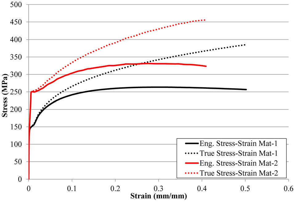
Stress-Strain diagrams of the materials.
Mechanical properties of the materials.
The investigated factors’ features
Table 3 shows all six different parameters that are studied in relation to their effect on over-bending. The input parameters can be divided into two categories. The first category comprises parameters related to the initial product’s features, such as strip thickness, radius of corners, material strength, and flange width. The second category includes parameters of the production line, such as bend angle increment, and inter-distance between successive stands.
Input parameters and their levels.
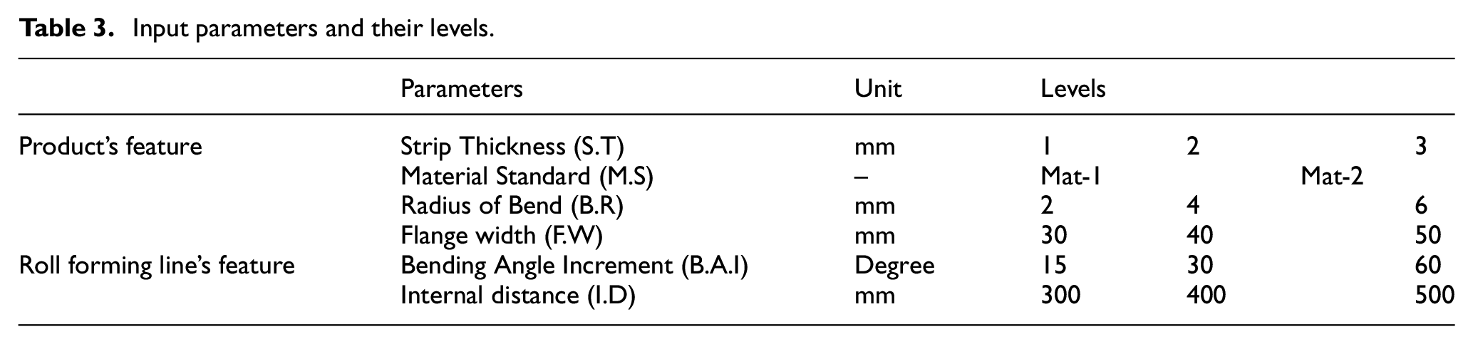
The bend angle increment determines how many forming stands are required to bend the strip. In this study, three bending angle increments have been tested. Figure 4 shows the sequence of forming stands based on the bending angle increment.
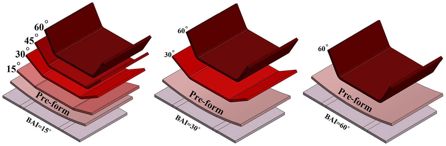
Configuration of roll forming steps in different bending angle increments.
The minimum and maximum values of the parameters have been determined by the limitation of roll forming process and the experimental setup of the study.
Finite element analysis of the cold roll forming process
Over-bending can be predicted by monitoring the stress strain distribution in different regions of a roll formed product. In particular, the normal stress in the bending lines can be used to predict the bending angle. In this study, Abaqus 6.14 finite element analysis has been used to simulate the roll forming process. Depending on the bending angle increment, different numbers of forming stands were designed in Abaqus. The geometrical features of the rolls and strips in the simulation were the same as those in experimental setup. Since the cross section of the final product is symmetrical, only half of the forming line was modeled.19,20
The configuration of the rolls and strip at the beginning of the simulation is shown in Figure 5. As can be seen in this figure, there are two pairs of guide rolls at the beginning of the forming line to adjust the strip along the forming rolls and prevent strip movement at the beginning of the simulation. 21 The figure brings forward a big gap (“d” in Figure 5) between the lower pre-form roll and the strip at first, which barely touches the upper pre-form roll. In the first step, the lower pre-form roll comes up to form the head of strip and then all rolls rotate to push the strip through the line, and be formed by each stand. The gap between the upper and lower rolls is 0.1% less than the strip thickness such that there is enough friction force to grab the strip between the forming rolls. 22
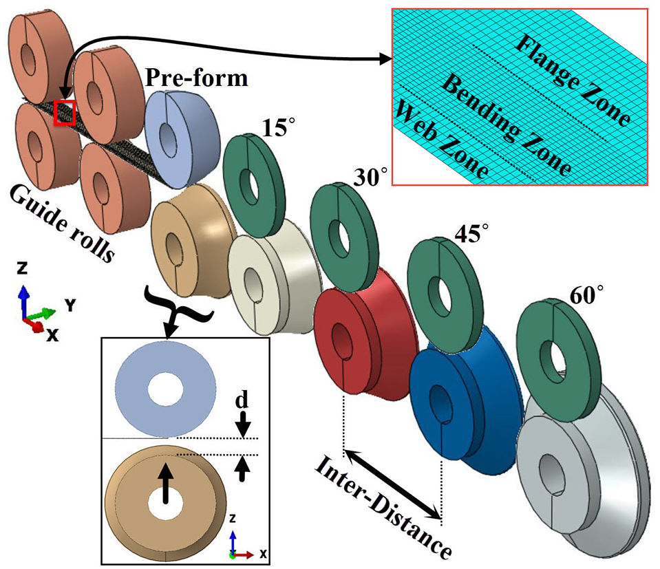
Arrangement of simulated roll forming line.
In the simulation, the rolls were considered as rigid bodies, while the strip was considered as a 3D deformable shell part. Because the mechanical properties of the strips were the same in different directions, they were considered isotropic. 23 Four-node shell element (S4R), with 11 integration points through thickness, was used to mesh the strip. 24 A convergence test was performed to find the best size for the elements. 25 The elements in the bending zone region were smaller than those in flange and web zones, because the bending zone goes through more deformation. 26
The speed of forming in the simulation was defined as equal to that in experimental tests. However, the speed was low enough to perform the process in quasi-static mode. To define the tangential behaviors between the strip and rolls, the modified coulomb friction model, along with the penalty mode with a friction coefficient of 0.1, was defined in the simulations.27,28
Experimental setup features
The experimental tests were done in three sequences. First, the strips were cut, based on each sample’s geometrical parameters. Then, the roll forming line was adjusted with the required parameters and the strip was formed through the line. Finally, the roll formed samples were cut by EDM wire and the angles were measured using profile projector.
The experimental setup had five forming stands which could each move along the forming direction. The two rolls in each stand were driven by an electromotor. Figure 6 shows a forming stand with its components. As can be seen in this figure, each upper roll consisted of several disks: the middle (B), and sides (A). In order to adjust the bending radius (R), the side disks of the upper roll were replaced with the disk that has required radius at the corners. Also, the lower rolls have multiple disks (C) and conical parts (D) which are assembled together on the lower shaft.
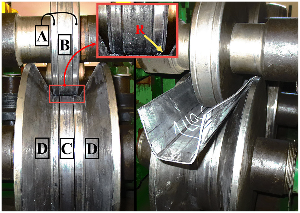
Forming stand in loading (right) and unloading (left) mode and its components.
The usage of three-piece rolls in the stands increased the flexibility of the experimental setup such that the forming parameters listed in Table 3 could be setup on the machine easily.
Figure 7 shows a three-stand roll forming setup that was used in one of the experiments. As can be seen in the figure, in addition to the forming stand, a couple of guide rolls were used at the beginning of the line to align the strip with the forming direction. Edge buckling is a common defect in the roll forming products, especially when large deformations occur, such as large bending angle increment. 29 To avoid such defects, a pair of pre-form rolls at the beginning of the line were used. Depending on the bending angle increment, different numbers of forming stand were installed for each test. 30 The speed was set at 37 mm/min, in order to avoid any vibration and keep the process in a quasi-static mode.
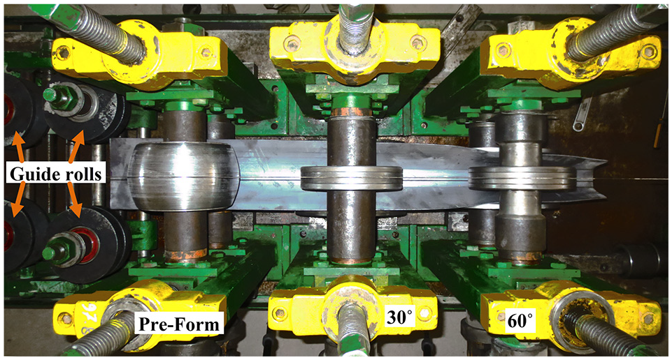
Roll forming setup with three forming stands. 30° BAI, and inter-distance 300 mm.
The last step of the experiment consisted in cutting a short specimen from the half length of each roll-formed sample, and measuring the bend angles on both ends of the specimen.
Results and discussion
The simulation results were verified with experimental tests, by drawing the simulation diagrams of over-bending on all result diagrams, and comparing them. Figure 8 shows the method used to get the results from simulations. As can be seen in this figure, the bend angle and the maximum lateral strain were measured through a path that is from the inter-distance between two successive stands following the head of the strip. This study determined the element of maximum lateral strain, locates on the bending line, and investigated the evolution of this element from the beginning of the process to the end.
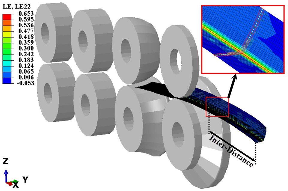
Data acquisition method in the simulations.
The difference between simulation and experimental results in all diagrams did not exceed 6.5%. Therefore, simulations of roll forming can accurately predict over-bending.
The effect of per-form rolls in the forming process
This study includes a wide range of parameters in order to bring forward the maximal values of over-bending. However, some of the parameters disabled the forming of the strips in the roll forming line. One of the disabling parameters was bending angle increment. With a bending angle increment of 60°, the strip could not be formed without the usage of the pre-form rolls. Figure 9 shows the sample that was going to be formed by 60° rolls without using preform rolls.
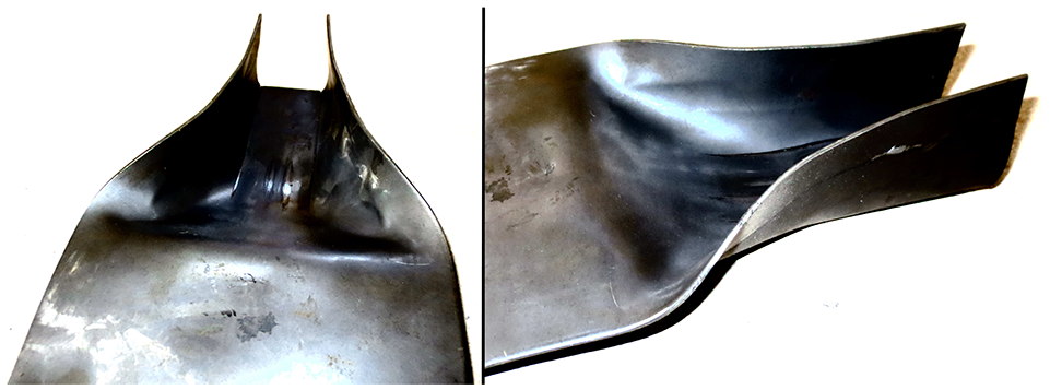
Formed strip in 60° B.A.I without the help ofpre-form rolls.
In this example, a set of flat rolls (0° angle) and 60° angle rolls were installed on two stands. During the forming process, however, the strip could not go past the 60° angle rolls. Figure 9 also shows that even if the forming of the strip were possible, the over-bending would be very high. However, using pre-form rolls to make the products would reduce the over-bending significantly (Figure 10). Therefore, the usage of pre-form rolls in a roll forming line has a positive impact on the quality of the end product.
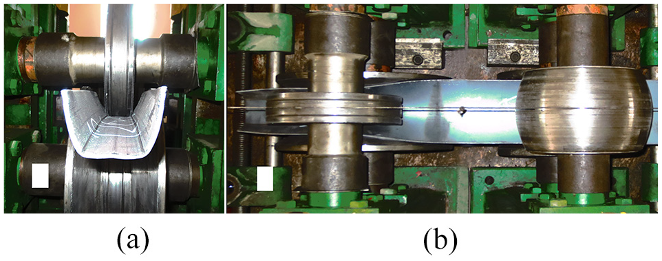
Front (a) and top (b) view of Formed strip in 60° B.A.I with the help of pre-form rolls.
The effect of Pre-form rolls on the over-bending confirms that the impact of forming stands at the beginning of the roll forming line is higher than those at the end of the line.
The effect of bending angle increment onover-bending
Figure 11 shows the effect of bending angle increment on over-bending. As can be seen in this figure, increasing the bending angle increment can increase the over-bending.
Effect of bending angle increment on over-bending.
By decreasing the number of forming stand, the deformation applied on the strip in each stand increases greatly. Figure 12 shows the maximum lateral strain at the bending line during the forming process. When the strip goes through each stand, the maximum lateral strain on the bend line increases suddenly, represented by a sharp step in the diagram.
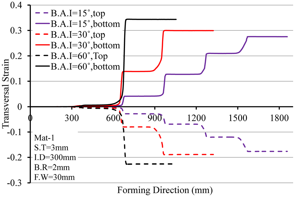
Lateral strain of the bend line according to different bending angle increments.
Adding stands in the production line adds steps to the lateral strain history, with each step becoming smaller as the number increases. Therefore, increasing the number of stands decreases the final plastic strain in the samples.
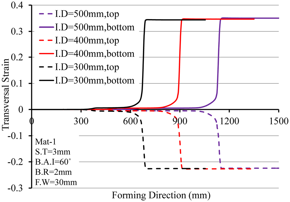
The effect of internal distance between the successive stands on over-bending
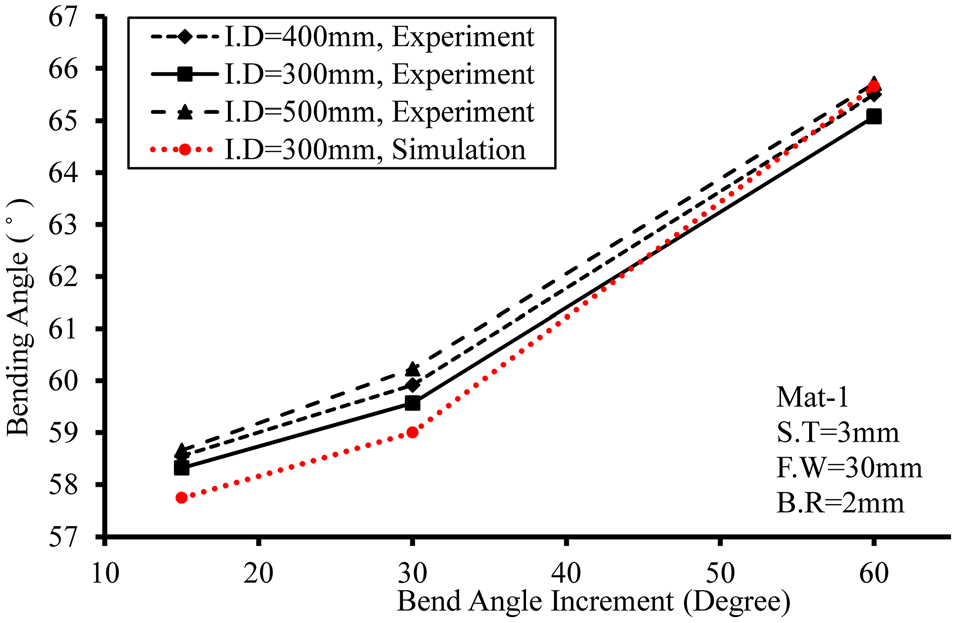
Figure 13 shows the effect of inter-distance between successive stands on over-bending. According to the figure, the inter-distance between successive stand has a very small effect on over-bending. Several studies have discussed critical deformation length,31,32 with the conclusion that is the distance between the stands is higher than the critical deformation length, increasing the distance no longer plays a role in the strain values of the products. 33 A small inter-distance causes smoother deformation in the strips.
Effect of inter-distance between the successive stand on over-bending.
Figure 14 demonstrates that the inter-distance distance between successive stands has a small effect on over-bending, by showing the maximum lateral strain on the bending line across samples formed in varying inter-distances between stands. According to this figure, the inter-distance between successive stands has little impact on the maximum lateral strain.
Lateral strain of the bend line through the forming process of the strips, with different inter-distances.
The small increase in the lateral strain can be caused by the strip recovering space and springing back once it comes out of the stand, if it has enough space to do so. This implies the strain will be more intense on the next stand, to compensate for the recovered space. The strain is minimized when there is not enough space for the strip to recover and spring back.
The effect of strip thickness on over-bending
Figure 15 shows that thicker strips are more prone to over-bending than thinner ones. Figure 16 brings forward the unavoidability of over-bending for thicker strips, because the top and bottom surfaces of thicker strip experience higher values of transversal strain. Figure 15 also confirms the effectiveness of bending angle increment in minimizing over-bending. As seen in this figure, the over-bending values for the samples that went through more forming stands is less than those that went through less forming stands.
Effect of strip thickness on over-bending.
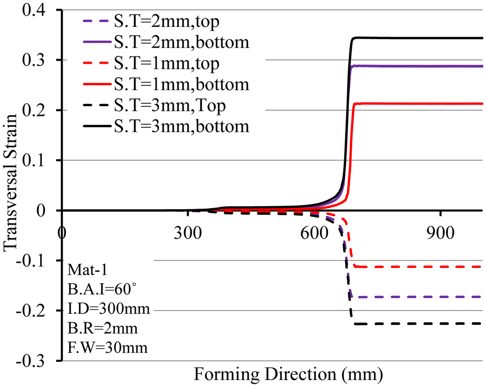
Lateral strain of the bend line through the forming process on the strips with different thicknesses.
The high amount of over-bending for ticker strips is linked to the fact that a big portion of the materials through the thickness direction experience high volume of transversal stress, which is transferred to irreversible plastic phase. Figure 17 shows the transversal stress through thickness direction at the point of maximum transversal strain on the bending line. As seen in this figure, not only do thicker materials experience a higher value of transversal stress, but the ratio of the regions that experience plastic stress in thicker strips is much higher than that in thinner ones.
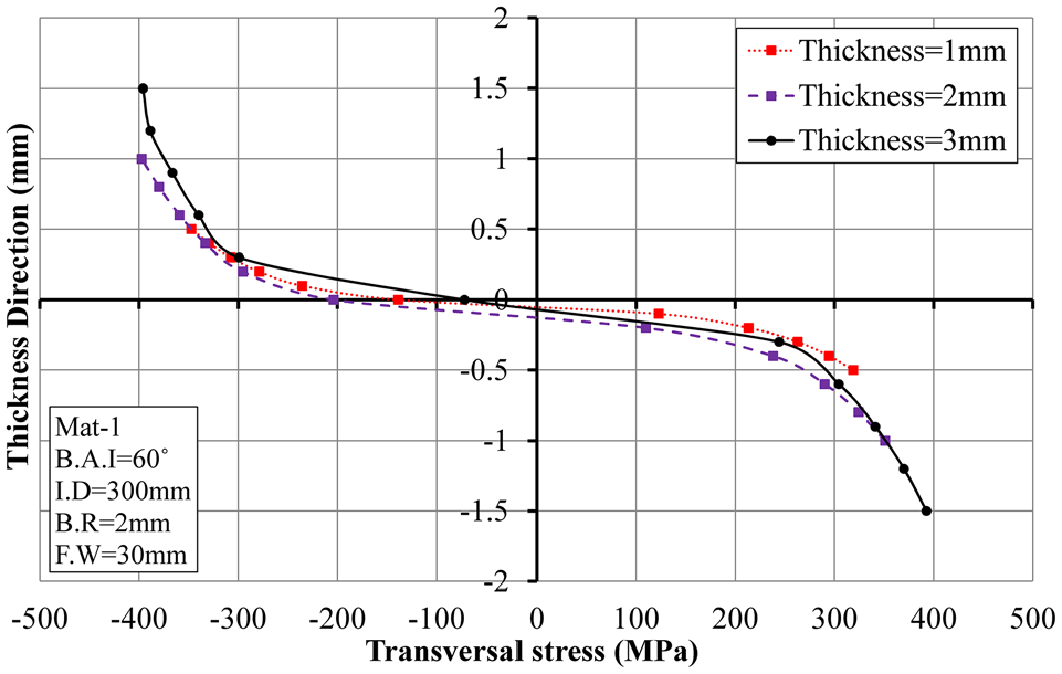
Transversal stresses on the bending line in strips with different thicknesses.
Therefore, the resistance against springback is higher in the bending process of thicker strips. There is a reverse relationship between thickness and springback occurring after the bending process. Therefore, with thicker materials, the higher volume of stress and absence of springback increases over-bending.
The effect of bending’s radius on over-bending
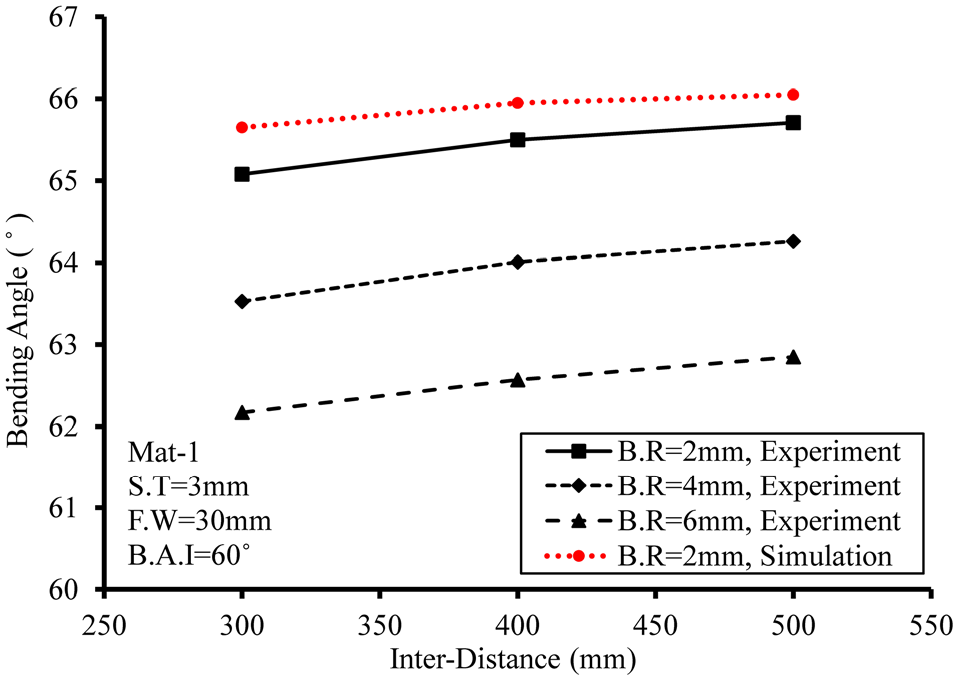
Figure 18 shows the effect of bending radius on over-bending. As seen in this figure, a small radius increases over-bending. This is explained in Figure 19. As seen in this figure, there is high transversal strain on the outer and inner layers of the strip formed with a small bending radius, which increases over-bending of the sample immensely.

Effect of bending radius on over-bending.
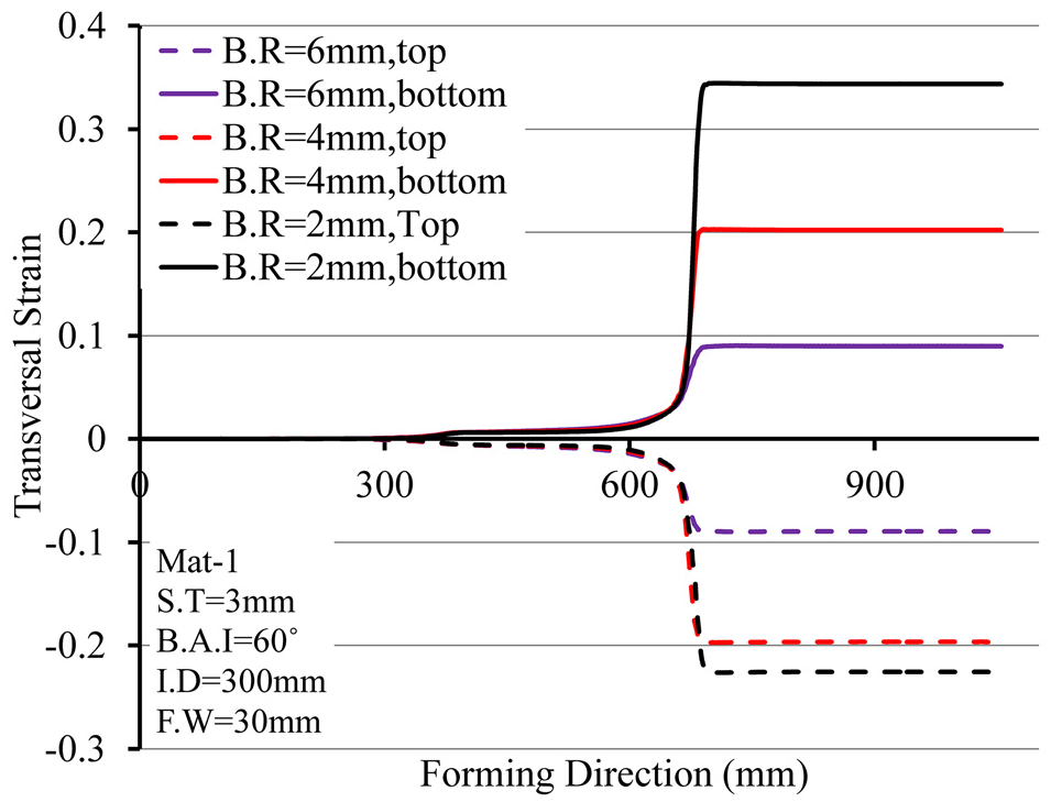
Lateral strain of the bend line through the forming process on the strips with different bending radii.
Figure 20 shows the transversal strain through the path. Although the transversal strain in the smallest radius is high, the area experiencing maximum transversal strain is small, whereas when the bending radius is bigger, a larger area experiences maximum strain. This explains why there is no significant difference in the over-bending of samples with different radii, even though the transversal strain differences are remarkable.
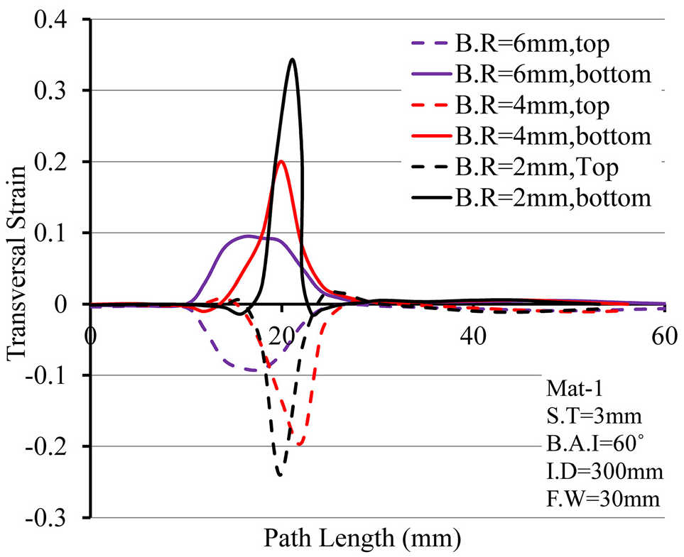
Lateral strain of the path on the strips with different bending radii.
The effect of flange width on over-bending
Figure 21 presents the effects of the flange width on over-bending. As shown in this figure, an increase in flange width reduces the over-bending. The samples with larger flange width have higher rigidity during the roll forming process and undergo less strain values in different directions.5,34
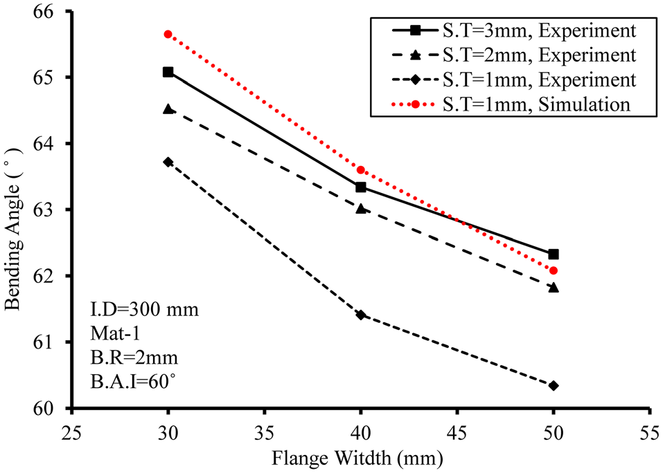
Effect of flange width on over-bending.
As seen in Figure 22, the maximum transversal strain in the bending line decreases when the length of the flange increases. Therefore, the shorter flange width samples experience more plastic deformation in comparison with large flange width samples, suggesting the elastic deformation on short flange width is less than large one. This explains why shorter flange width samples undergo more over-bending than samples with larger flange widths.
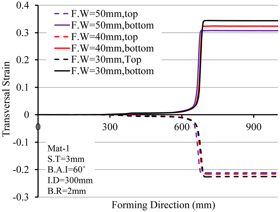
Lateral strain of the bend line through the forming process on the strips with different flange widths.
The effect of different materials on over-bending
As mentioned before, in the design of experimental tests, two materials were used. Material 1 (Mat-1) is mild steel capable of high deformation, while material 2 (Mat-2) is a higher strength steel with less formability. Figure 23 shows the over-bending of samples with different materials. As seen in this figure, over-bending of samples made of Mat-1 is higher than that made of Mat-2.
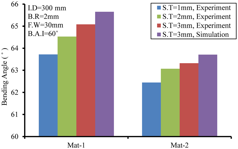
Effect of materials properties on over-bending.
Figure 24 shows the transversal strain on the bending line during the roll forming process. The transversal strain records at bending line show less amount of strain on the sample made of Mat-2. High strength steels are more resistant to deformation and spring back more than mild steel. Therefore, high strength steels undergo less over-bending than mild ones.
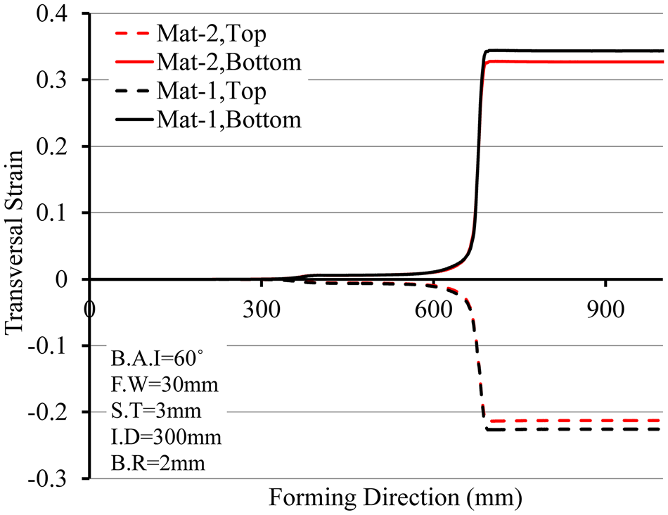
Transversal strain of the bend line according to different materials.
Failure possibility in the simulation of roll forming process
Due to the high value of transversal strain exerted on the bending line, the roll forming process can fail. To investigate the occurrence of failure, a path on the product with the highest value of transversal strain was observed. The thickness across the path at the end of the forming process is shown in Figure 25. In this study, the failure criterion suggested by Kumar et al. 35 was used.
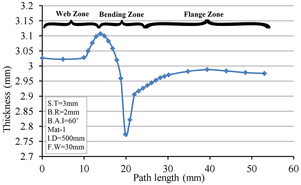
Thickness of the path at the end of the roll forming process.
According to this criterion, localized necking is perceived by the presence of a critical thickness gradient in the vicinity of the neck. Necking happens when the thickness ratio reaches the critical value C (see equation (1)).
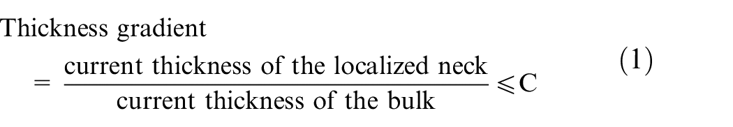
To measure C, three tensile tests were done. The thickness of the neck, as well as the thickness of the area adjacent to the neck were measured at the neck’s initiation. 36 The value of C for Mat-1 was 0.84. The maximum value of thickness gradient for the curve in Figure 25 is 0.893, therefore the deformation didn’t reach to necking point.
Evaluation of the factors
To evaluate the effect of bending angle increment, flange width, strip thickness, inter-distance between the successive stands, bending radius, and mechanical properties of the materials on over-bending, the linear regression method was used. The set values of each factor and their corresponding over-bending results from experimental tests were entered into the Minitab Software to fit the curve. 37 Table 4 shows the results of analysis of variance (ANOVA) which estimate the effect of each parameter on over-bending. Due to high R2 value of analysis, the nonlinear regression was ignored. 38 In this table, p-values show the effect of each factor on over-bending. For each factor, the lower its p-value, the higher its effect on over-bending. Generally, the factors with p-value higher than 0.05 have negligible effect on over-bending. 39 As seen in this table, p-values of all factors are less than 0.05, so all factors correlated to over-bending.
Results of analysis of variance (ANOVA).
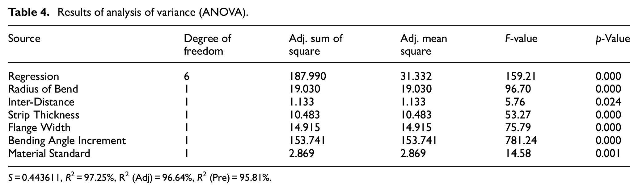
S = 0.443611, R2 = 97.25%, R 2 (Adj) = 96.64%, R2 (Pre) = 95.81%.
F-values in Table 4 show the effect of each factor on over-bending. The higher the F-value, the more significant effect the corresponding factor has on over-bending. The factors can be organized from the most to the least effective on over-bending. Because the material is a qualitative factor, the maximum tensile strength of each material was considered to represent the effect of different materials on over-bending, thus turning it into a quantitative factor. According to the F-value of each parameter in the analysis of variance, bending angle increment in each forming stand is the most effective factor for over-bending, and that the bending radius was found to be the second most significant parameter, while the inter-distance between the successive stands has the least effect on over-bending. The standardized effect of factors on bending angle is shown in the Pareto chart of Figure 26.
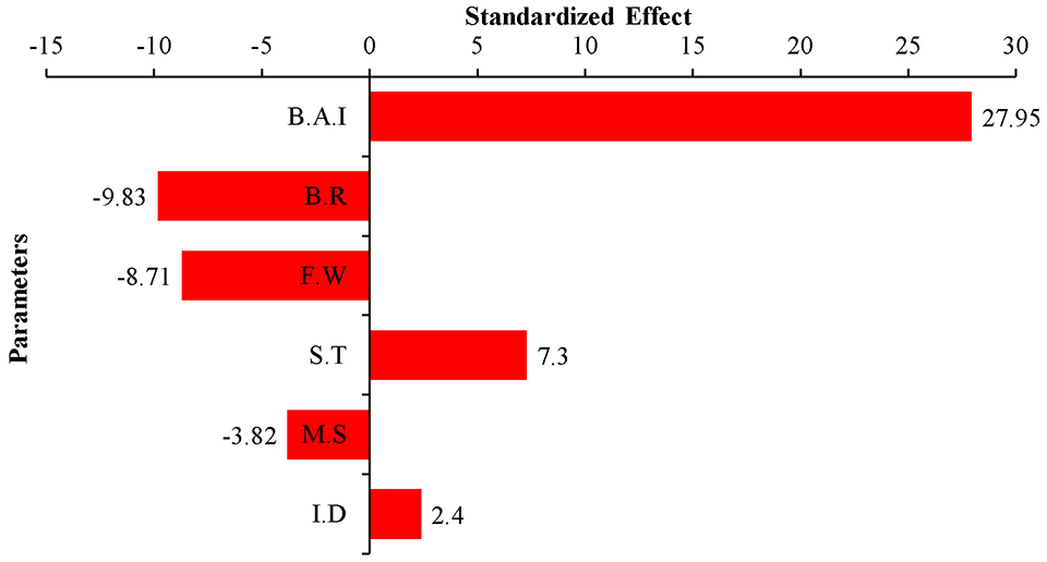
Pareto chart of standardized effects of factors on over-bending.
The positive and the negative values of each factor indicate whether the factor has a positive or reverse relationship to over-bending. Since over-bending eliminates springback, every parameter that positively affects over-bending can reduce springback, and vice versa. Therefore, increasing the bend radius, flange width, and material strength can increase the springback since they have a reverse relationship to over-bending. Equation (2) was derived from the regression method to predict the bending angle.
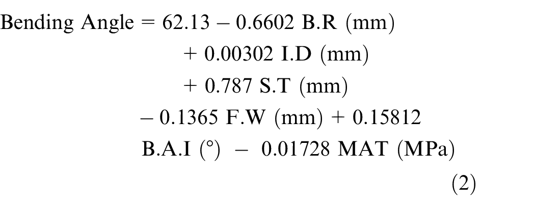
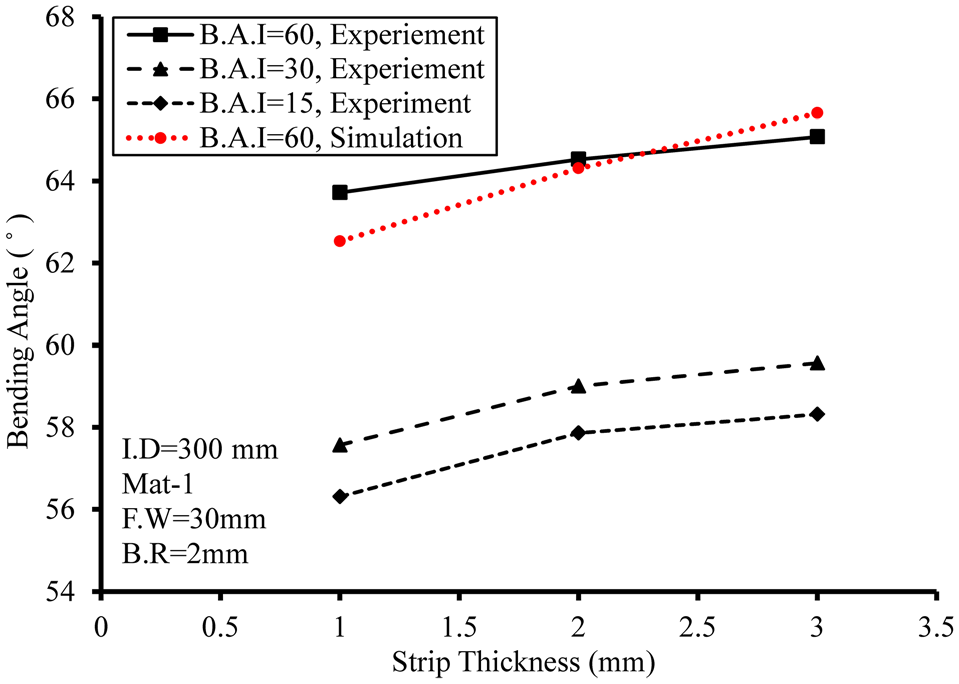
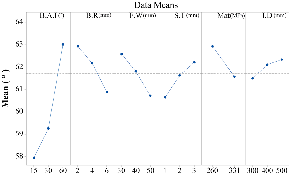
Figure 27 shows the main effect plot that uses data means and shows the effect of each input parameters on bending angle independent of other input parameters. The dashed line in the figure is the mean of all bending angles across input parameter levels. The points in this plot are the raw data mean of the bending angle at various levels of each input parameter. As seen in the figure, the effect of each parameter on the bending angle in the regression is the same as the one shown in Figures 11, 13, 15, 18, 21, and 23, which confirms the accuracy of the regression method.
Main effects plot for bending angle.
As seen in this figure, a decrease of bending angle increment (or increasing the number of forming stands in the roll forming line) not only eliminated over-bending but also caused springback, and the bending angle will be less than the designed value, especially from B.A.I 60° to 30°, although only one forming stand has been added to the roll forming line, the bending angle decreases from 63° to 59.25°.
Discussion and conclusions
In this research, the effect of six parameters, including bending angle increment, strip thickness, flange width, bending radius, inter-distance between the successive stands, and the mechanical properties of different materials on over-bending were investigated. The input parameters were assigned two or three values depending on the design of the experiment. The experimental tests were conducted using a five-stand roll forming machine. The over-bending of each sample was measured. Then all experiments were simulated to investigate the stress and strain distribution through different directions on different areas. Finally, the effect of each parameter on over-bending was shown and the parameters were sorted based on the nature and the intensity of their effect on over-bending. The following conclusions can be derived from the test results:
Among investigated parameters, bending angle increment is the most effective one. According to the results, increasing the number of stands from 2 to 5 can reduce the over-bending and change the angle from values higher than the angle of the rolls to those less than roll angle.
Inter-distance between the successive stands has the least effect on over-bending. It is better to reduce the length of the roll forming line to reduce the required materials for the roll forming machine.
The use of pre-form rolls at the beginning of the roll forming line is highly recommended. Production of 60° channel section in one stand is impossible, especially when the flange length is larger than the web width. Using pre-form rolls at the beginning of the roll forming line can facilitate the deformation process of the strips.
The bending radius is an important factor in the fold angle of channel sections. The proper values of the bending radius insure fold angle accuracy and avoid any possible springback or over-bending. However, it is required to check the history of the strains in the critical point to avoid any failure.
High strength materials are more prone to springback in the roll forming process than mild steels. According to the results, the higher the strength of the material, the less over-bending occurs in the channel section.
Footnotes
Declaration of conflicting interests
The author(s) declared no potential conflicts of interest with respect to the research, authorship, and/or publication of this article.
Funding
The author(s) received no financial support for the research, authorship, and/or publication of this article.