
Abstract
Heat resistance, heat stableness and corrosion resistance are properties that predispose nickel superalloys such as Inconel 625, Mar-M247, Nimonic C 263 and B1914 to a very wide range of applications. Due to their mechanical properties, their machinability by conventional technologies is relatively difficult, so wire electrical discharge machining (WEDM) is widely used, where only one condition is placed on the material being machined, which is at least minimal electrical conductivity. Despite the fact that the main element of which these superalloys are always composed is nickel, their machinability by WEDM is quite different. For this reason, an extensive study comparing the machinability of the four above-mentioned nickel superalloys using WEDM was performed, examining the effect of setting the machine parameters on the cutting speed as well as on the quality of the surface and subsurface layer. It was found out that the cutting speed is different for individual materials with the same set of machine parameters and so that it is possible to significantly increase the quality of the machined surface for individual materials.
Keywords
Introduction
The emergence of unconventional or progressive technologies is conditioned by higher demands on manufactured components, whether in terms of shape complexity, dimensional accuracy, time and financial demands, or the use of new materials in production. Wire electrical discharge machining (WEDM) is one of the methods of machining electrically conductive materials, in which repetitive electric discharges occur between two electrodes in a dielectric environment. One electrode is the workpiece and the other acts as a tool. The tool in the form of a wire has a diameter of 0.02 up to 0.3 mm and is made of brass, copper, molybdenum, tungsten or is composite or coated.1–3 The main difference compared to conventional machining methods is the fact that the tool is not in direct contact with the workpiece, so no cutting forces are generated. The removed material in the form of small balls with a diameter of micrometres is created by eroding using individual electrical pulses from the machined semi-finished product. Further material removal is created also due to evaporation, as temperatures of 10,000°C–20,000°C are at the cutting point during the eroding process. 4
Nickel superalloys are specially developed alloys that are used in areas requiring heat resistance, heat stableness and corrosion resistance. In terms of use, they are used mainly for components of combustion turbines and their components in the aerospace, energy and automotive industries. These alloys are mainly characterised by high-temperature strength above 650°C, dimensional stability at these temperatures and resistance to corrosion and fatigue.5,6
Wire electrical discharge machining is a technological process whose requirements for surface quality and machining efficiency are constantly increasing, not only due to its increased energy consumption. The main reasons are emerging materials; whose conventional machining is often very problematic or requires special tools. A detailed understanding of the WEDM process is therefore essential for the long-term sustainability of the competitiveness of this production technology, which depends on dozens of input facts. The WEDM machining of special materials, such as nickel alloys, has not yet been compared in any study. For this reason, this extensive experiment was performed, comparing the machinability of nickel alloys Inconel 625, Mar-M247, Nimonic C 263 and B1914, both in terms of the cutting speed, that is, machine times, and the resulting quality of the surface and subsurface layer. The occurrence of defects is a major shortcoming affecting the expected life or proper functionality of the component. This study builds on and draws on the findings of previous studies on WEDM machining of individual materials such as Hardox, 7 Mar-M247, 8 Creusabro, 9 nickel alloy B1914 10 or aluminium alloy 7475-T7351. 11 The findings presented in this study will be used primarily for the development of WEDM machining in the aerospace, automotive and energy industries.
Wang et al. 12 studied the micro-grooving process of abrasive air-jet on quartz crystals, where they focussed on the influence of the process parameters on most measures of the grooving performance like groove width, surface roughness, groove depth and kerf taper. It was proved that the abrasive air-jet technology is very effective for the machining of quartz crystals. Antil et al. 13 tried to foresee optimal parameters for obtaining the maximum material removal rate during the WEDM process of silicon carbide particle/glass fibre-reinforced polymer matrix composites. For this prediction they used a metaheuristic approach and algorithm. The design of experiment includes the Taguchi’s methodology as well. The results showed that the maximum material removal rate (MRR) was received by differential evolution algorithm which also has a better collective assessment capability. Zhang et al. 14 investigated the rotary ultrasonic machining of optical K9 glass which is considered to be a difficult-to-machine material. The compressed air was used as a coolant. They studied the influence of the input variables, such as federate, ultrasonic power and spindle speed, on the output variables like cutting force, ultrasonic power consumption, edge shipping size and surface roughness. Newton et al. 15 studied the formation of the recast layer during the WEDM process of Inconel 718 and its characteristics. The parameters which influenced the increase of the recast layer were peak discharge current, energy per spark and current pulse duration, where the recast layer had the average thickness but was highly variable in nature. Li et al. 16 investigated Inconel 718 as the experimental material while studying the surface integrity characteristics during the WEDM process. It was shown that high discharge energy caused the dominance of coral reef microstructure, predominantly discontinuous and non-uniform thick white layers, while low discharge energy caused the dominance of random micro voids and reduce the average roughness. Ajay et al. 17 focussed on three various nickel-based alloys that were machined with WEDM. Taguchi method was employed for the experiments and four different machining parameters were considered, such as wire feed rate, pulse on/off time and current. Having compared the obtained results, they pointed out the optimum parameters for the WEDM machining of all alloys used for the experiments. Unune and Mali 18 studied the process of micro-WEDM which was employed for Inconel 718. Apart from the low-frequency workpiece vibration, the following parameters like capacitance, gap voltage, vibrational frequency and feed rate were considered. As the performance factors, kerf width and material removal rate were selected. It was found out that the capacitance proved to be the most significant parameter that influenced both kerf width and material removal rate. The micro-WEDM performance together with the material removal rate was improved due to the low-frequency workpiece vibration. Sharma et al. 19 focussed on Inconel 706, which is rather a new superalloy employed in the industries. They were trying to optimise the surface roughness and material removal rate using the hybrid approach. Having employed the microstructural analysis, it was revealed that some microglobules, microholes and melted debris were formed on the machined surface, although there was not a single microcrack on the alloy surface. Sharma et al. 20 again studied Inconel 706 as the experimental material for the assessment of the performance characteristics of the WEDM process. The following factors, like surface roughness, material removal rate, microhardness, topography, recast layer, metallurgical and microstructural changes were assessed. It was determined that the number of micro voids and micro globes was much lower at high servo voltage and low pulse on time, although it causes a thick recast layer. Rao and Venkaiah 21 used a cuckoo search algorithm in order to optimise the WEDM process when machining Inconel 690 with the two-stage initialisation. The above-mentioned algorithm proved to be very efficient and accurate compared to other methods. In order to test the performance of the algorithm used, benchmark functions were employed in the experiments.
Experimental setup and material
Experimental material
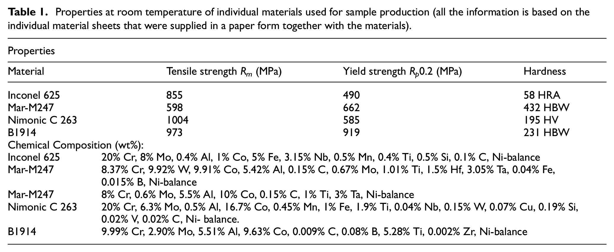
The samples for the experiment shown in Figure 1(a) were made of nickel alloys Inconel 625, Mar-M247, Nimonic 263 and B1914, the microstructures of which are shown in Figure 1(b). Their chemical composition given by the standard and mechanical properties is shown in Table 1. Materials Mar-M247 and B1914 were donated by the company PBS Velká Bíteša.s. where they were cast. Nickel superalloys are heat-resistant, heat-stable and corrosion-resistant, have dimensional stability and high-temperature strength at 650°C. They are most often used for the production of turbine blades and turbocharger wheels capable of operating at increasing temperatures, which, however, do not exceed 1000°C. They are also used as construction materials for aerospace and aviation. For the experiment, starting semi-finished products with a thickness of 10 mm were used, while the section length of each sample was always 3 mm.
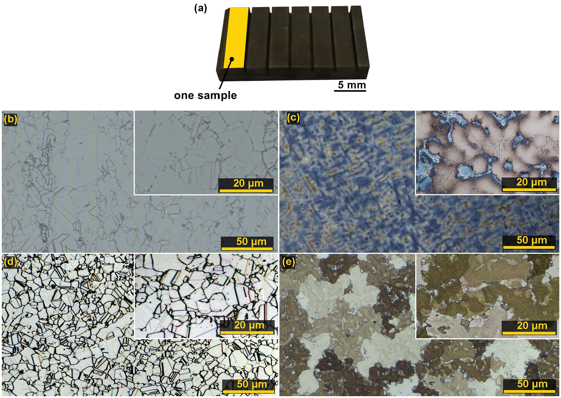
(a) An example of samples produced in the experiment, (b) the microstructure of the Inconel 625 material, (c) the microstructure of the Mar-M247 material, (d) the microstructure of the Nimonic C 263 material and (e) the microstructure of the B1914 material.
Properties at room temperature of individual materials used for sample production (all the information is based on the individual material sheets that were supplied in a paper form together with the materials).
WEDM machine setup
For the machining, a five-axis wire electrical discharge machine of the EU 64 type from the company MAKINO was used, equipped with a precise CNC control of all axes and a pull-out bath enabling complete immersion of the workpiece in a dielectric liquid. Deionised water was used as the dielectric fluid, and the tool electrode was a brass wire of the CUT E type from the company PENTA TRADING with a diameter of 0.25 mm with a tensile strength of 1000 N/mm2.
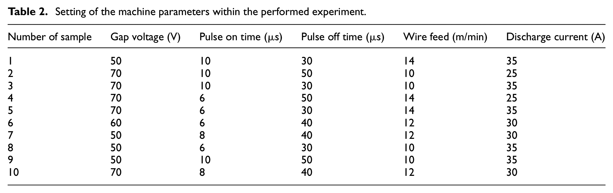
In this study, the experiment was based on monitoring the influence of five independent machine setting parameters, which were: pulse off time (Toff), gap voltage (U), discharge current (I), pulse on time (Ton), wire feed (v). Thus, a total of 40 experimental samples were produced, always 10 from each material. The individual setting values of these parameters are listed in Table 2 and were determined based on the machine manufacturer’s recommendations and extensive previous tests.22,23
Setting of the machine parameters within the performed experiment.
Experimental methods
Samples made of individual materials with different settings of machine parameters were studied using scanned electron microscopy (SEM) on a Lyra3 type microscope from TESCAN. This microscope was additionally equipped with an energy-dispersive X-ray detector (EDX). Metallographic preparations for the study of the subsurface layer were produced by conventional techniques – wet grinding and polishing with diamond pastes using the automatic preparation system TEGRAMIN 30 supplied by the company STRUERS. The final mechanical-chemical finishing was performed with the OP-Chem suspension also from the company STRUERS. After etching with kalling’s etchant, the samples were observed by electron and light microscopy (LM) using Axio Observer Z1m from the company ZEISS. The topography of the machined surfaces was analysed using a Dektak XT contact 3D profilometer from the company BRUKER. With the help of this device, 3D reliefs of surfaces were also created. The measured data were further processed in Vision 64 and Gwyddion software. Using a Helios-type electron microscope from the company THERMO FISHER SCIENTIFIC, which was additionally equipped with a focussed ion beam (FIB), a lamella was produced. This lamella was designed to study the material composition using a transmission electron microscope (TEM) of the Titan type from the company THERMO FISHER SCIENTIFIC.
Results and discussion
Evaluation of the cutting speed
The cutting speed is a very important parameter in unconventional wire cutting technology, because it cannot be easily set when programming the machine, but is controlled by the machine itself, which regulates this speed itself based on parameter settings so that the tool never touches the workpiece. The used WEDM machine showed this speed during the machining of individual samples on the display, from where it was recorded in the graph shown in Figure 2. It is clear from the graph that the samples of Nimonic C 263 were cut with the highest speeds, but with the absolute highest speed of 4.3 mm/min Sample 1 from Inconel 625 was machined with the setting of machine parameters: U = 50 V, Ton = 10 µs, Toff = 30 µs, v = 14 m/min and I = 35 A. This maximum cutting speed is slightly higher than that observed on the contrary when machining Hadfield steel with the same material thickness, which was presented in the Mouralova et al. 8 study. In contrast, when machining AISI 4140 steel of the same thickness, the speed was significantly lower, which was presented in the Tosun 24 or Datta and Mahapatra 25 studies. In contrast, the lowest cutting speeds were recorded for the material B1914 and Mar-M was machined at slightly higher speeds, which did not exceed 3.05 mm/min for any sample. The cutting speeds show not only the effect of setting individual machine parameters but also the different mechanical and physical properties of individual nickel alloys. The Discharge current parameter had the most positive effect on the cutting speed of Inconel 625 and Nimonic C 263 materials, when the highest cutting speeds were achieved when it was set to the maximum value of 35 V. For other materials, this positive effect of current on the cutting speed is less apparent. Based on these findings, it would be possible, of course, taking into account the required mechanical properties, to choose a faster cutting nickel alloy and thus make the machining process more efficient.
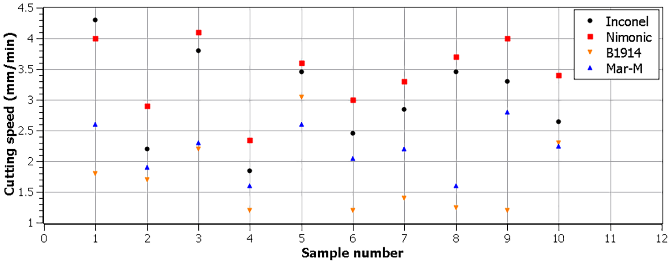
The cutting speed of individual samples.
Evaluation of the topography of sample surfaces
Specific topography requirements are always placed on the surfaces of the machined parts, mainly on the basis of the required functionality of the given surfaces. During the machining process, however, various influences act on the machined surfaces, plastic deformation occurs due to mechanical or thermal effects, the hardness of the surface layer changes or various defects in the form of cracks or torn material occur. The surface topography has a significant effect on the correct functionality and service life of components, such as the accuracy of machine parts, their noise, friction losses, heat transfer or wear resistance. For this reason, two profile parameters (arithmetical mean deviation of profile Ra, the maximum height of profile Rz) were evaluated on the surfaces of all machined samples, always in five random places on each sample, while arithmetic mean was created from the evaluated values. The topography parameters and 3D reliefs were evaluated using a Dektak XT contact profilometer according to the corresponding standard for profile ISO 4287, 26 while the evaluated parameters Ra and Rz were compiled into the graph in Figure 3(a) and (b). It is clear from these graphs that the lowest values of the parameter Ra were reached during the machining of the alloy B1914 in Samples 6, 7 and 8, when the lowest value was 2.2 µm. Unfortunately, the lowest cutting speed was achieved for these samples at the same time. The material Mar-M 247 also achieved very good results, when the lowest values of Ra 2.5 and 2.55 µm were achieved in Sample 4 and 6. However, Sample 4 was again cut at a very slow speed of 1.6 mm/min, but Sample 6 already was cut at a speed of 2 mm/min. The fastest cut sample from Inconel 625 had a Ra of 4 µm but a Rz of only 22 µm, which is one of the average values. However, the samples from Inconel had in almost all cases the lowest values of the parameter Rz. The values of Ra parameters are consistent with other studies such as Li et al. 16 or Yang. 21 The Discharge current parameter also had an effect on the final value of the evaluated parameters in the topography, however, as with the cutting speed it cannot be said unequivocally that for Inconel 625 and Nimonic C 263 the maximum Discharge current value also meant the maximum value of the topography parameters. 3D reliefs shown in Figure 3(c) to (f) show only a slight difference in the change in morphology and distribution of individual craters on the samples with the lowest Ra values for individual materials.
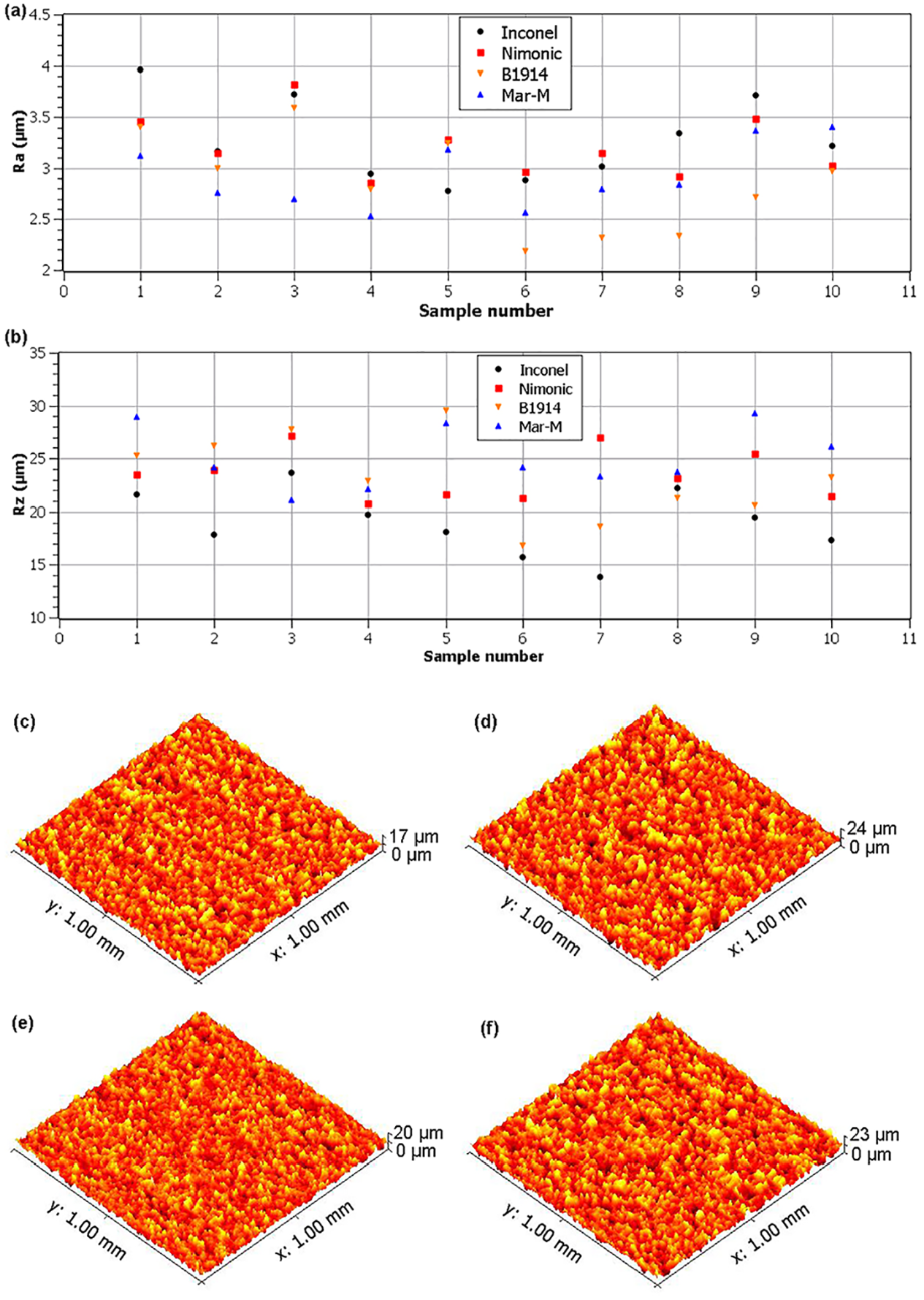
(a) The evaluated parameters Ra for individual samples, (b) the evaluated parameters Rz for individual samples, (c) 3D relief of Sample 6 from B1914, (d) 3D relief of Sample 4 from Mar-M, (e) 3D relief of Sample 5 from Inconel and (f) 3D relief of Sample 8 from Nimonic.
Morphology of the machined surfaces, the analysis of the chemical composition and subsurface area
The technology of wire electrical discharge machining creates a very specific and unique morphology, which is formed by individual craters created after electric discharges, which removed the material of the workpieces in the form of small balls. At the same time, there was also significant evaporation of the material and its complete melting to a depth in micrometres, followed by very rapid cooling with a dielectric liquid. The shape, frequency of occurrence or depth of individual craters is determined by many factors, which was presented in the study by Tosun and Pihtili 27 or Wang et al. 28 This rapid melting and re-cooling cause the occurrence of a recast layer, which is very typical for WEDM. This layer contains elements from the wire electrode, which have been transferred from the wire to the workpieces due to intense diffusion processes due to very high temperatures. From the point of view of coatings with which the machined surface of the part can be subsequently covered, the recast layer is relatively problematic, because the recast layer together with the coating can peel off when getting in contact with another part. This would create places where the paint would be completely missing, which could limit or damage its proper functionality. However, the main quality parameter is the occurrence of defects in the surface and subsurface layer, because wire electrical discharge machining of some materials or the use of machine parameter settings causes the formation of surface or subsurface cracks or the formation of burnt cavities. The study of the surface morphology of all machined samples was performed using a Lyra3 electron microscope. A secondary electron (SE) detector was used for imaging in all cases, and the samples were always studied at a magnification of 1000×, 2500× and then 4000×. A backscattered electron (BSE) detector was used in all cases to analyse the cross-sections of the sample.
Samples of Inconel 625 had a very different morphology, which is shown in Figure 4(a) and (b) for the best and worst samples in terms of the topography parameter Ra. It can be seen from the figure that on Sample 5 machined with machine setting parameters U = 70 V, Ton = 6 µs, Toff = 30 µs, v = 14 m/min and I = 35 A, no adhering eroded balls remained, as is the case on Sample 1, which is almost entirely covered with a recast layer and small balls. These balls were also studied on HSLA steel and pure titanium materials and were presented in the Azam et al. 29 and Kumar et al. 30 studies. The smooth surfaces in Figure 4(a) are very specific because the microstructure of the material being machined is evident in some places. The fact that the surface of this sample was not contaminated with almost any elements from the wire electrode is proved by the analysis of the chemical composition on the basis of which only 3.9 wt. % Cu and 0.5 wt. % Zn was diffused on the surface. The surfaces of all samples were without torn findings and the same applies to subsurface areas in which no defects were found. The thickness of the recast layer varied greatly from sample to sample, with the smallest amount and thickness being achieved in Sample 5, as evidenced by the section of the sample shown in Figure 4(c). Such a smooth surface, essentially completely without a recast layer, is very unusual and from this point of view, Sample 5 has an exceptionally high surface quality, which is usually achieved only after several wire cuts using the so-called Multicut technology.
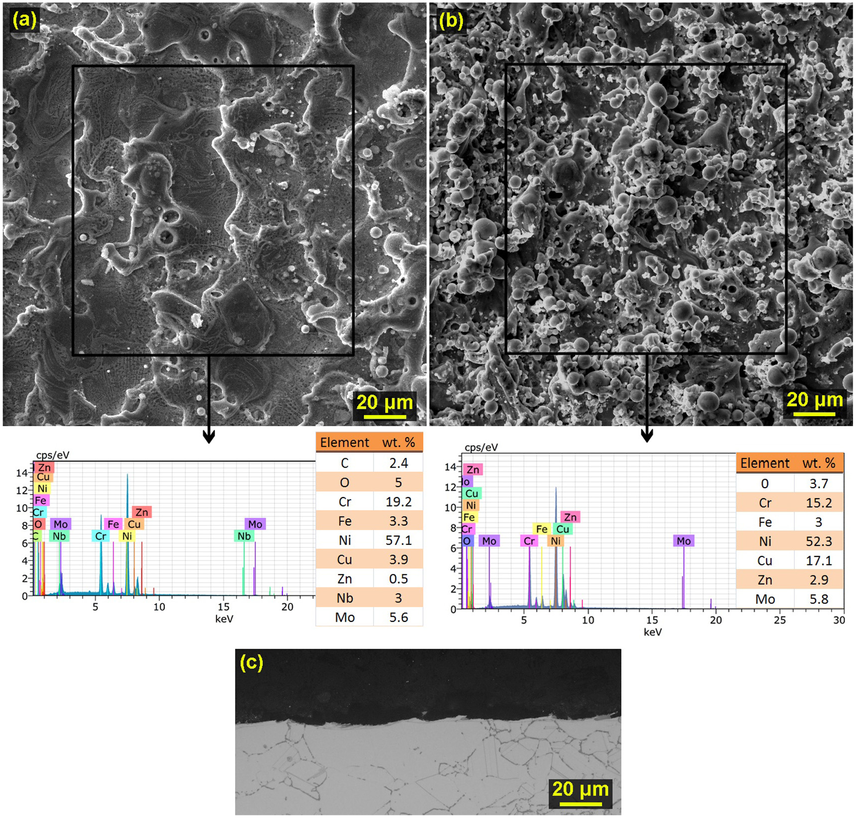
Surface morphology of samples from Inconel 625 material, including marking of the places where EDX analysis was performed and the resulting analysis spectrum (a) Sample 5 machined with the machine setting parameters: U = 70 V, Ton = 6 µs, Toff = 30 µs, v = 14 m/min and I = 35 A, (b) Sample 1 machined with machine setting parameters: U = 50 V, Ton = 10 µs, Toff = 30 µs, v = 14 m/min and I = 35 A and (c) cross section of Sample 5.
The surface morphology of all samples made of Mar-M247 was relatively similar, and for the two samples with the lowest Ra value and the highest, it is shown in Figure 5(a) and (b). From these two images, it is clear that the surface is covered with about 50% of the recast layer, which is formed according to the performed EDX analysis partly of copper and zinc originating from the wire electrode. The remaining surface, that is, 50%, consists of the base material without this heat-transformed layer. The thickness of the recast layer does not exceed more than 10 µm anywhere. On the contrary, the smooth places, the bottoms of the craters, were not contaminated with elements from the wire electrode almost at all. Such diffusion processes have also been studied on other materials, such as martensitic stainless steel AISI 440A 31 or high-speed tool steel ASP 23. 32 However, a cross-section of the sample revealed cracks that spread through coarse carbides and extend to a length of 10 µm. These cracks were studied in all samples, with about 10 cracks appearing on each sample in a 3 mm cut.
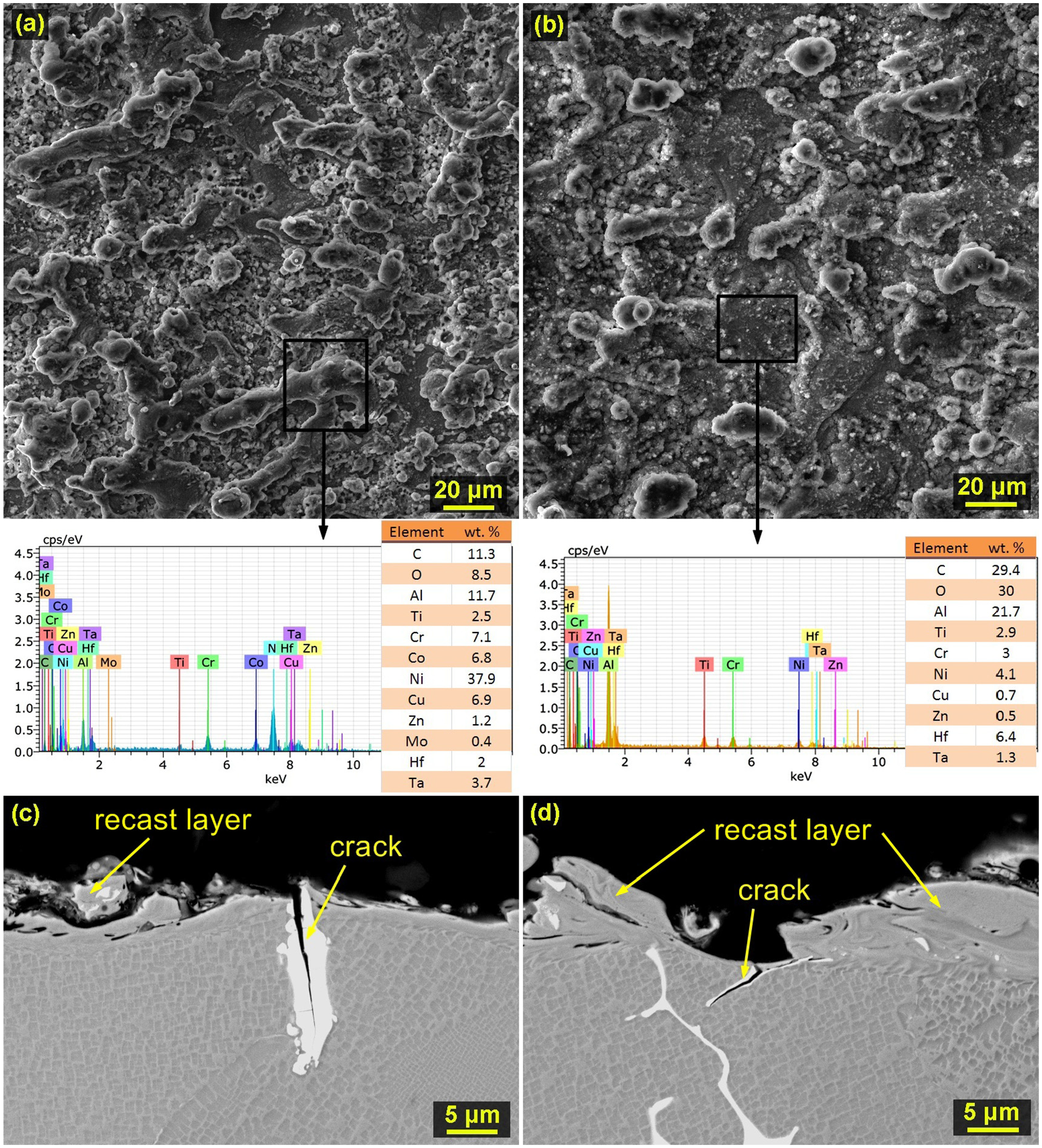
Surface morphology of samples made of Mar-M247 material, including marking of places where EDX analysis was performed and the resulting analysis spectrum: (a) Sample 10 machined with machine setting parameters: U = 70 V, Ton = 8 µs, Toff = 40 µs, v = 12 m/min and I = 30 A, (b) Sample 4 machined with machine setting parameters: U = 70 V, Ton = 6 µs, Toff = 50 µs, v = 14 m/min and I = 25 A, (c) cross-section of Sample 10 and (d) cross-section of Sample 4.
The samples made of Nimonic material all had a similar morphology (Figure 6(a) and (b)), with the distribution of the recast layer on the surfaces being relatively uniform and between them, there were smooth bottoms of the individual craters. The recast layer was again formed by diffused elements from the wire electrode and the smooth bottoms of the craters contained significantly lower contamination of copper and zinc. From the cross-sections of the sample shown in Figure 6(c) and (d) it is clear that the subsurface layer does not contain any defects, which was also found in the study of Bisaria and Shandilya 33 or Sonawane and Kulkarni. 34 The thickness of the recast layer is relatively thick and ranges up to 20 µm. It covers almost the entire surface of the samples without exception, so there are no smooth spots on the surfaces containing only the base material of the workpieces.
Surface morphology of the samples made of Nimonic C 263 material, including marking of places where EDX analysis was performed and the resulting analysis spectrum: (a) Sample 4 machined with machine setting parameters: U = 70 V, Ton = 6 µs, Toff = 50 µs, v = 14 m/min and I = 25 A, (b) Sample 3 machined with machine setting parameters: U = 70 V, Ton = 10 µs, Toff = 30 µs, v = 10 m/min and I = 35 A, (c) cross-section of Sample 4 and (d) cross-section of Sample 3.
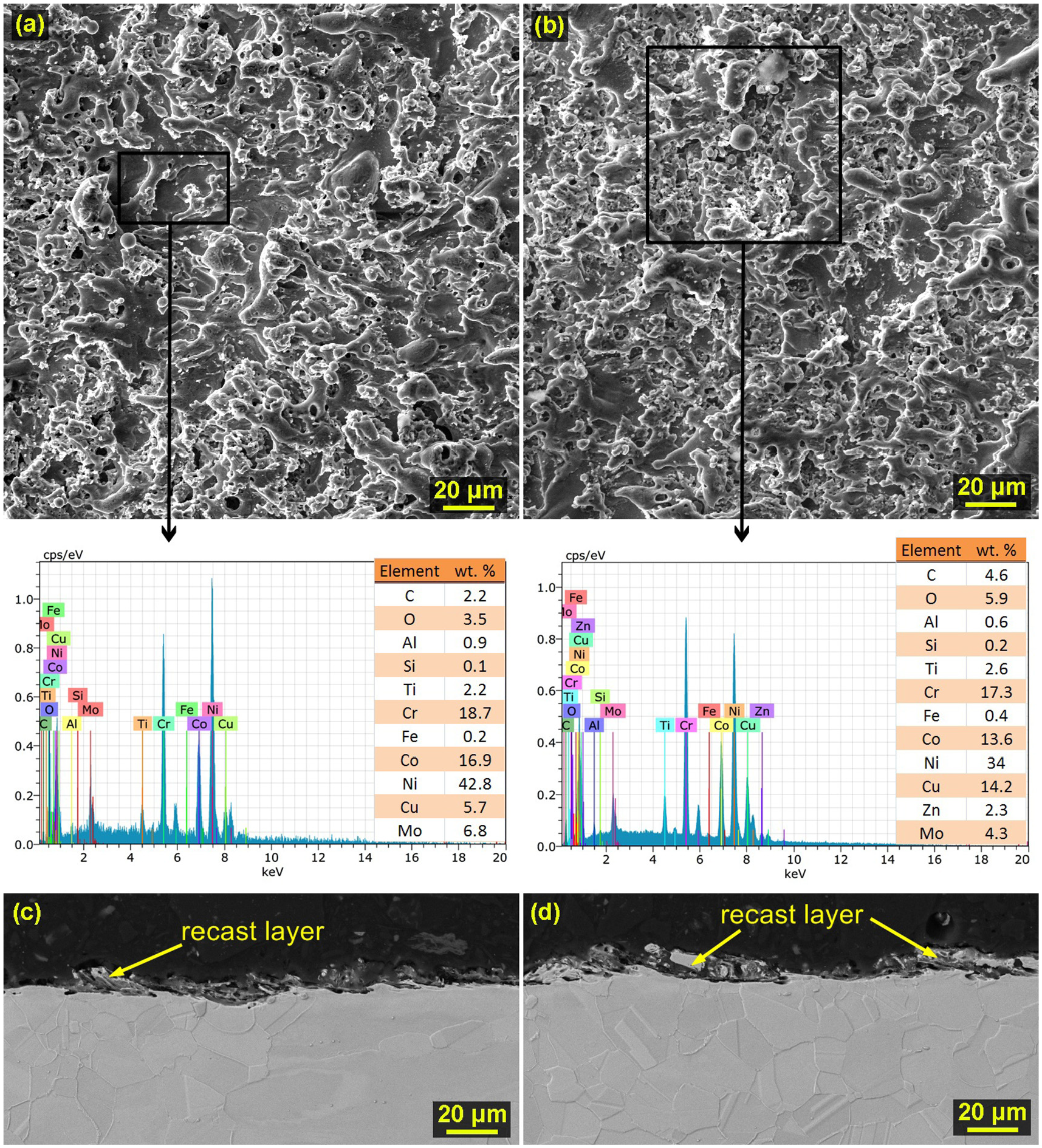
The surface morphology of the samples made of B1914 material was relatively different for the individual samples and differed mainly in the amount of the recast layer, which contained diffused elements from the wire electrode. The morphology of the sample with the surface with the evaluated lowest parameter of the topography Ra is shown in Figure 7(a), while this Sample 4 was machined by setting the machine parameters U = 70 V, Ton = 6 µs, Toff = 50 µs, v = 14 m/min and I = 25 A. It can be seen from the picture that on its surface there is a significantly smaller recast layer, as evidenced by the cross-section of the sample shown in Figure 7(c), where the thickness of the recast layer does not exceed 15 µm. The recast layer here covers only about 30% of the entire sample surface. In contrast, Sample 3, the morphology of which is shown in Figure 7(b) and a cross-section of Figure 7(d) shows that the recast layer is almost continuous and reaches a thickness of 20 up to 40 µm. Here, the occurrence of the recast layer is much more frequent and covers basically the entire surface of the sample. It can be said that its layer is basically completely continuous. Again, the surface and subsurface layers do not contain any defects in any of the experimental samples.
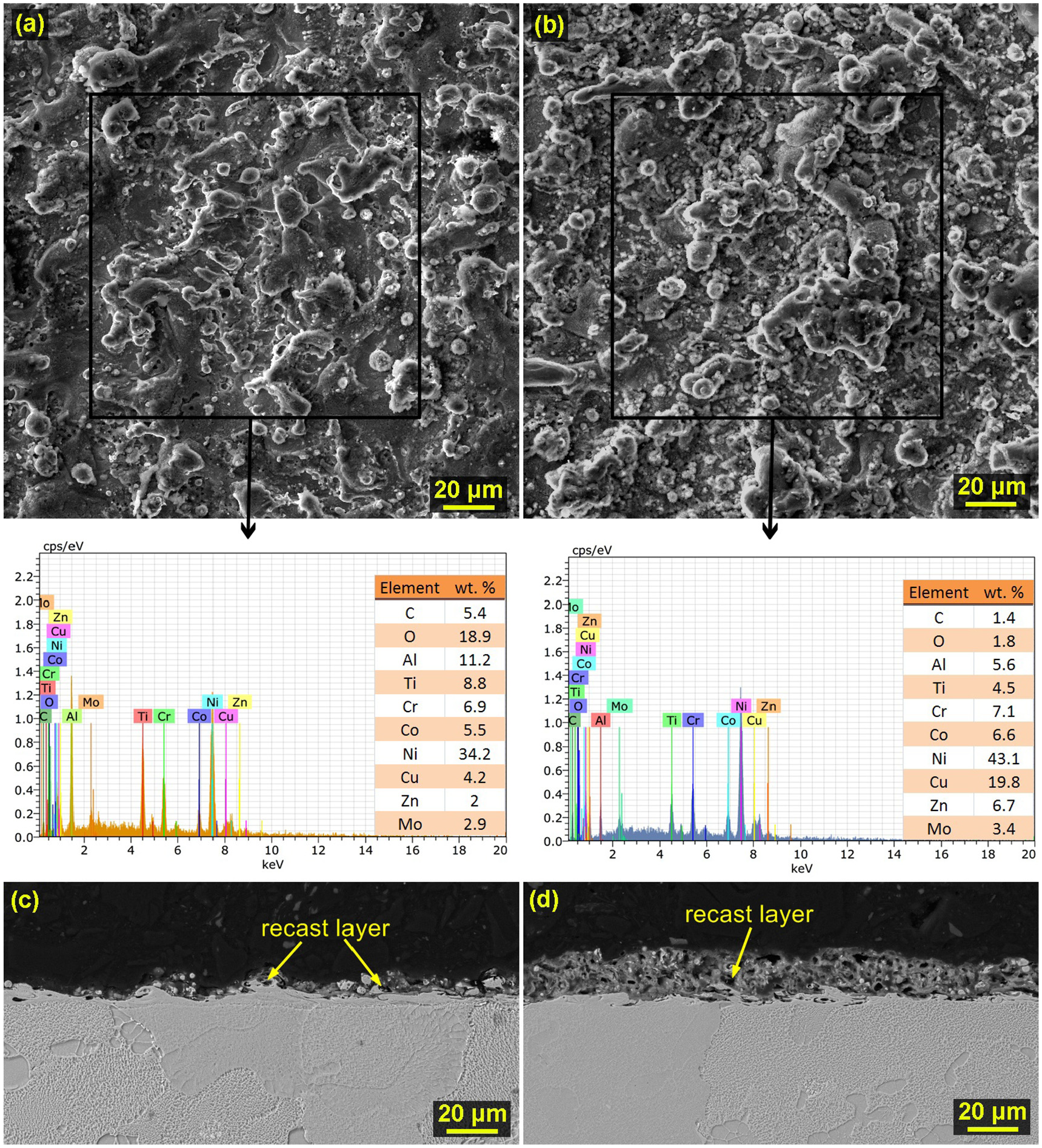
Surface morphology of the samples from the material B1914 including marking of the places where EDX analysis was performed and the resulting spectrum of analysis: (a) Sample 4 machined with machine setting parameters: U = 70 V, Ton = 6 µs, Toff = 50 µs, v = 14 m/min and I = 25 A, (b) Sample 3 machined machine setting parameters: U = 70 V, Ton = 10 µs, Toff = 30 µs, v = 10 m/min and I =35 A, (c) cross-section of Sample 4 and (d) cross-section of Sample 3.
TEM analysis of lamellae
A Helios electron microscope equipped with a focussed ion beam (FIBID) and an electron beam (EBID) was used to produce all TEM lamellae. A Titan G2 transmission electron microscope with an accelerating voltage of 300 kV set in a scan mode (STEM) with a beam current of 2 nA was used to measure the chemical composition. Each of the examined lamellae was created in the same way. First, a suitable place was found with an adequate amount of recast layer to which the protective metal was applied. A double-sided trench with a depth of 15 µm and a width of 30 µm was dug around this metal using an ion beam, which enabled the subsequent cutting and attachment of the lamella by means of a nanomanipulator to a copper holder, where the lamella was thinned to 0.2 µm from a thickness of 2 µm.
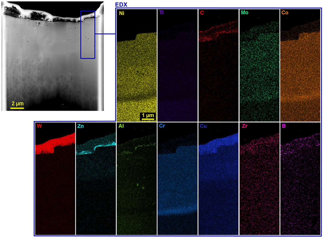
A lamella of the Inconel 625 material was made from Sample 1 and is shown in Figure 8, including the designation of the place selected for the chemical composition analysis. From the study of this lamella, it is clear that during the machining there was an intensive diffusion of elements from the wire electrode and their subsequent mixing in the recast layer, which here reaches a thickness of 3 µm. Chromium, niobium and manganese also oxidised in the recast layer due to the high-temperature decomposition of water into hydrogen and oxygen during the machining process. The elements carbon, cobalt, aluminium, silicon and titanium were contained in the lamella in a very low concentration, therefore they were not included in the maps of element distribution.
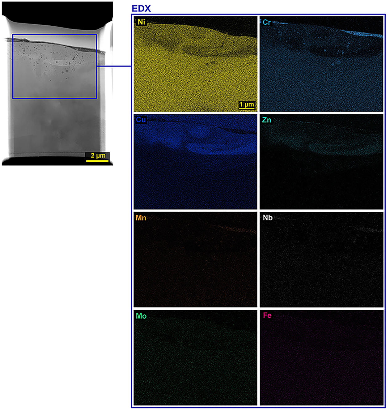
STEM image of the lamella from Inconel 625 with the marked place of EDX analysis of elements and their individual maps.
The lamella made from Sample 4 of the Mar-M247 material is shown including the individual element maps in Figure 9. The elements molybdenum, iron and titanium were detected only in very small concentrations, therefore their map is not shown here. The recast layer area here is formed by homogeneously distributed elements except for boron and hafnium, which show a higher concentration here. Furthermore, copper and zinc originating from the wire electrode are present in the recast layer, which is a common diffusion phenomenon. In the base material, all elements are evenly distributed.
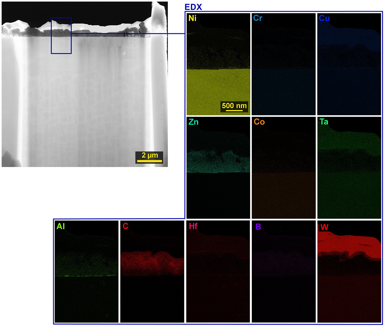
STEM image of the lamella from Mar-M247 with the marked place of EDX analysis of elements and their individual maps.
Figure 10 shows a lamella made of Nimonic C 263 from Sample 4 with individual element distribution maps. The elements niobium, tungsten, vanadium and carbon were contained in very small concentrations, so their map was not shown here. From the maps in Figure 10, it is clear that in the recast layer there was an increase in the concentration of chromium, copper, titanium and zinc, which diffused from the used brass electrode. The resulting titanium particles are visible in several places, with a low content of aluminium and also chromium.
STEM image of the lamella from Nimonic C 263 with the marked place of EDX analysis of elements and their individual maps.
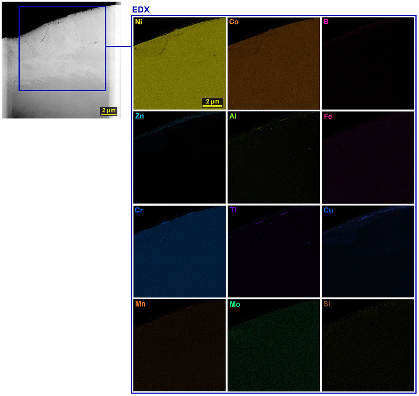
The lamella produced from Sample 4 of material B1914 is shown in Figure 11, including maps of individual elements. In addition to the elements of the material being machined, tungsten was also added, which served as a protective covering layer for the entire lamella during its production. Furthermore, the elements of zinc and copper were added, which diffused from the brass wire electrode into the machined material. In the area of the recast layer, the concentration of carbon, aluminium, boron and zirconium increased and, in contrast, other elements decreased. From the map of aluminium, it is evident that in several places its higher concentration was formed and circular aluminium particles were formed.
STEM image of the lamella from B1914 with the marked place of EDX analysis of elements and their individual maps.
Conclusions
In order to compare the machinability of individual nickel superalloys, which were Inconel 625, Mar-M247, Nimonic C 263 and B1914, an extensive experiment was performed, which monitored the effect of setting machine parameters not only on the cutting speed of individual alloys but also on the surface and subsurface layer quality. Based on many of the analyses performed, the following conclusions were reached:
- samples made of Nimonic C 263 material were cut at the highest speeds, but Sample 1 was machined with the absolute highest 4.3 mm/min (machine setting parameters: U = 50 V, Ton = 10 µs, Toff = 30 µs, v = 14 m/min and I = 35 A) from Inconel 625, on the contrary, the lowest cutting speeds were recorded for material B1914,
- the lowest values of the parameter topography Ra were achieved during machining of alloy B1914, when the lowest value was 2.2 µm, the samples from Inconel 625 had in almost all cases the lowest values of the parameter Rz,
- the morphology analysis revealed that in Sample 5 (machine setting parameters: U=70 V, Ton=6µs, Toff=30 µs, v=14m/min and I=35 A) from Inconel 625 no adhering eroded remained balls as was the case on the surfaces of other samples of this material,
- the surface morphology of all samples made of Mar-M247 was relatively similar, with about 50% recast layer coverage, the same was studied for samples made of Nimonic C 263,
- the surface morphology of the samples made of B1914 material was relatively different for individual samples and differed mainly in the amount of recast layer, which contained diffused elements from the wire electrode, while the thickness of the recast layer ranged from 15 to 40 µm,
- the cracks were studied only in the samples made of Mar-M247 up to 10 µm in length, however, they were found on all 10 samples produced without the exception,
- the analysis of the produced TEM lamellas showed the diffusion of copper and zinc into the workpieces and, in the case of Inconel, also its considerable mixing.
From the above-mentioned conclusions, it follows that the only material prone to cracking limiting the correct functionality and service life of the components is the Mar-M alloy, which allowed the slowest cutting, but had the lowest parameters of the Ra topography. In contrast, between Inconel 625, B1914 and Nimonic C 263 alloys, a choice is possible if it is more important to maximise the cutting speed, that is, reduce machine time, or maximise the quality of the machined surface from the topography.
Footnotes
Author contributions
Ales Polzer: Visualisation, Formal analysis. Katerina Mouralova: Conceptualisation, Methodology, Data curation, Writing-Original draft preparation, Writing-Reviewing and Editing, Supervision. Libor Benes: Validation, Funding acquisition. Radim Zahradnicek: Methodology, Data curation. Jiri Fries: Data curation, Funding acquisition.
Declaration of conflicting interests
The author(s) declared no potential conflicts of interest with respect to the research, authorship, and/or publication of this article.
Funding
The author(s) disclosed receipt of the following financial support for the research, authorship, and/or publication of this article: CzechNanoLab project LM2018110 funded by MEYS CR is gratefully acknowledged for the financial support of the measurements/sample fabrication at CEITEC Nano Research Infrastructure. This publication is a result of the project CACTU, Reg. No. CZ.02.1.01/0.0/0.0/17_049/0008397, which has been co-financed by European Union from the European Regional Development Fund through the Operational Programme Research, Development and Education. This project has also been financially supported by the Ministry of Industry and Trade of the Czech Republic which has been providing institutional support for long-term conceptual development of research organisation. The project CACTU has been integrated into the National Sustainability Programme I of the Ministry of Education, Youth and Sports of the Czech Republic (MEYS) through the project Development of the UniCRE Centre (LO1606).