
Abstract
Aerospace materials experience high levels of mechanical and thermal loading, high/low cycle fatigue, and damage from foreign objects during service, which can lead to premature retirement. Mechanical surface treatments of metallic components, for example, fan blades and blisks, are proven to improve fatigue life, improve wear resistance and avoid stress corrosion by introducing work hardening, compressive residual stresses of sub-surface, and surface finishing. Vibropeening can enhance aerospace materials’ fatigue life involving the kinetic agitation of hardened steel media in a vibratory finishing machine that induces compressive stresses into the component sub-layers while keeping a finished surface. Spherical steel balls are the most widely used shape among steel-based media and have been explored for decades. However, they are not always versatile, which cannot access deep grooves, sharp corners, and intricate profiles. Steel ballcones or satellites, when mixed with round steel balls and other steel media (diagonals, pins, eclipses, cones), works very well in such areas that ball-shaped media are unable to reach. However, a methodology of study the effect of irregularly-shaped media in surface enhancement processes has not been established. This paper proposes a finite element-based model to present a methodology for the parametric study of vibratory surface enhancement with irregularly-shaped media and investigates residual stress profiles within a treated area of an Inconel component. The methodology is discussed in detail, which involves a stochastic simulation of orientation, impact force, and impact location. The contrasting effects of a high aspect ratio, or an edge contact, as opposed to rounded and oblique contacts are demonstrated, with further analysis on the superposition of these effects. Finally, the simulation results are compared with actual residual stress measurements and was found to have a max percent difference of 34% up to 20
Introduction
Surface enhancement processes like shot peening and vibro-strengthening can yield beneficial compressive residual stress and improve the fatigue life of metal components in jet engines. In a shot peening process, small sphere particles are shot to the target surface with a velocity of 20–100 m/s, and a plastic deformation zone is generated on the sub-surface. X-ray diffraction (XRD) method is usually used to measure residual stress after peening effects. 1 However, it is costly and time consuming to measure residual stress experimentally. The finite element method (FEM) is one of the most effective ways to simulate the peening process. Guagliano 2 established a relationship between Almen intensity and the residual stress distribution by creating a finite element-based model of shot peening with five subsequent shot impacts. It is showed that it is possible to define the amount of kinetic energy transferred from the particles to the metal component during a shot peening process to Almen intensity through fitting analytical regression equations. Vibropeening was introduced by Feldmann et al., 3 which combines the effects of peening and vibratory finishing into one single step. The advantage of vibropeening technology is a highly polished surface and strengthened sub-surface, preventing crack initiation and propagation. Besides, the substitution of a single process in place of two processes can also translate into both high cost and time savings. However, non-uniform treatment and limited media accessibility on complex geometry are the main research areas in the vibropeening process, which still yet to be developed.
H-Gangaraj et al. 4 proposed a sequential explicit–implicit finite element model to investigate the effect of shot peening on mechanistic factors of fretting fatigue. They predicted the residual stress by the symmetry cell approach that combined with the idea of area average. Sangid et al.,5,6 proposed a computational model to predict the fatigue life based on a crack growth simulation, which accounted for residual stress effects, surface roughness effects, and mean stress relaxation. Rouquette et al. 7 presented a finite element model, including thermo-mechanical effects, to investigate the influence of temperature on residual stress of shot peening. It is showed that the temperature significantly affects the residual stress field for high shot velocities. Kim et al.8,9 applied combined peening factors to the three-dimensional symmetry-cell, which was originally proposed by Meguid et al. 10 They studied residual stress distribution concerning finite element peening coverage, repetition pattern, and impact sequence. Mahmoudi et al. 11 investigated the influence of initial residual stress on the shot-peened specimen using experimental and numerical approaches. Initial stresses can dramatically alter the shot peening residual stresses beyond the maximum compressive residual stress point.
In fact, coverage is one of the most critical parameters in the peening process. Several studies discuss FEM approaches to determine coverage evolution of shot peening recently with the advent of numerical simulation and finite element modeling. Based on the assumption of the Kirk and Abyaneh 12 model, Pham et al. 13 established a multi-impact approach to provide the required number of shots for coverage of 98%. The authors investigated a double-shot peening approach, where a smaller shot followed a large diameter shot combines the higher compressive stress induced by the bigger shots and smoother surface finish with the smaller shots. Another parameter that is of interest in peening processes is the resulting surface roughness. Aside from simulating the residual stress effects of shot peening, a study of Wu et al. 14 demonstrates surface roughness and topography’s evolution before and after processing with convincing results.
To overcome the deficiency of not capturing a realistic coverage and costly simulation of high coverage of existing models before, Hassani-Gangaraj et al. 15 introduced a variable dimension symmetry cell to simulate the surface nano-crystallization by severe shot peening successfully. Bagherifard et al. 16 developed a guided random impact pattern which used a reduced number of shots to provide full coverage on target surface. Gangaraj et al. 17 adopted a random finite element model to reflect a realistic shot peening process, and demonstrated the Avrami 18 equation leads to overestimation of impingement numbers at full coverage level in simulation unless the radius of treated area is at least 10 times of the single indentation radius. It is worth mentioning that random impact model is a suitable method to achieve a more realistic simulation of shot peening process.
Some studies combined both FEM and discrete element method (DEM) as an approach to numerically model shot-peening. Murugaratnam et al. 19 proposed a new computational model for shot peening based on both the discrete element and the finite element methods, conducted parametric analysis of several mechanical parameters, which indicated that the air pressure in the nozzle is the most important factor, followed by the mass flow rate and the duration of the peening process. It also showed that the computational model could predict the percentage of coverage, though not discussed in detail. Due to high computational cost of simulating the real shot peening process, Jebahi et al. 20 refined a 3D random DEM-FEM coupling model, which adjusted the dimension of representative elementary volumes to simulate industrial shot peening at affordable costs quantitatively. A more recent study by Marini et al., 21 approached shot-peening simulation using a combination of FEM and discrete element method (DEM) to evaluate the residual stresses particularly in the edges and tips of components. The impact velocities that they used for the FEM simulations was randomly generated from a stochastic distribution estimated from the DEM results.
Aside from DEM and FEM approaches, Nguyen et al. 22 on the other hand proposed a multiphase model based on Computational Fluid Dynamics (CFD) approach to predict the coverage of shot peening process. It is showed that a higher impact velocity leads to a higher level of coverage area due to a bigger indent area created.
Intensity and coverage are two universally accepted and adopted quantitative parameters in shot peening processes. The methodologies to measure residual stress experimentally through XRD and correlate the value of Almen intensity with residual stress in the shot peening process have been established, which can efficiently optimize and select experimental process parameters. However, another important parameter, that is, media shape, has not yet been investigated extensively, especially in numerical analyses. In practice, most of finite element model for multi-impact simulations developed recently did not focus on the influences of irregular media shapes on stress profile evolution but only on the general spherical media shape. Building confidence through simulation is important such that the benefits in terms of inducing residual stress during the surface enhancement process is maximized even before media shape selection and procurement. This serves as the motivation of this study to investigate the shape-based effect on the residual stress through development of a suitable finite element modeling methodology.
Methodology
Material model and damping
Material model
During the peening process, the Johnson-Cook constitutive model,
23
which takes the strain hardening and strain rate hardening into account, is one of the most widely isotropic hardening model adopted to demonstrate the kinematic hardening law. The equivalent flow stress
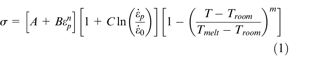
Where
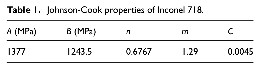
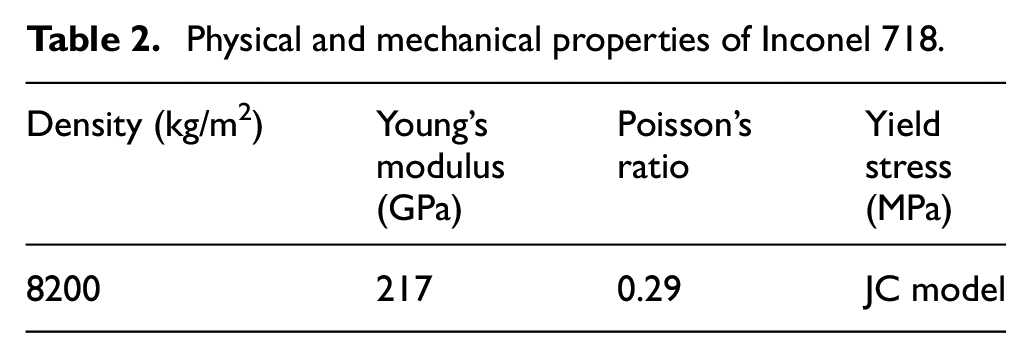
The material used in this study was Inconel 718, which is a Ni-based super-alloy widely used in aero engine industry. The Johnson-Cook model parameters utilized in the literature 24 as input for FEM simulation with the Inconel 718 are summarized in Table 1. It is worth noted that JC model parameters, mostly A, C, n, highly depend on heat treatment. The value of m will be set to zero if the thermal softening effect is not considered. The reference strain rate is set to 1 s−1. The physical and mechanical properties of Inconel 718 are given in Table 2. 25
Johnson-Cook properties of Inconel 718.
Physical and mechanical properties of Inconel 718.
Material damping
The surface enhancement process generally produces high-frequency stress oscillations. If these oscillations during right after impact are not diminished substantially before the following impact occurs, they may accumulate causing numerical instabilities in the model. In order to minimize this instability induced by improperly damped high-frequency oscillations during the post-impact process, it is important to introduce material damping into consideration.26,27 The material damping was given as:

where D is the damping matrix, M is the mass matrix, and K is the stiffness matrix.
On the basis of Meguid et al.,
27
the effective damping can be determined using the stiffness proportional damping coefficient
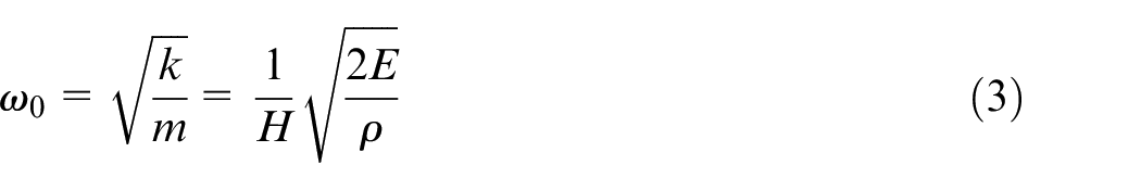
where E,

where
To define viscous damping, you must include it in a contact property definition. In order to decay the oscillations in between the impacts, the value of
FEM modeling
Governing equations, geometry, and boundary conditions
During the vibropeening process, the steel media movement can be a combination of rolling, sliding, and impingement. In order to simplify the problem, the movement of media particle was assumed to be the normal impact and the rolling and surface sliding was supposed to be negligible. Based on Abaqus Explicit, the general nonlinear dynamic system of equations for target workpiece with proper initial and boundary conditions can be established as follows:

where
Based on Newton’s second law, the governing equations for media are:

where
The impact force
The present work is focused on normal contact between media and target workpiece. The initial conditions for workpiece can be established as follows:
where
The initial conditions for media is shown in below:
where
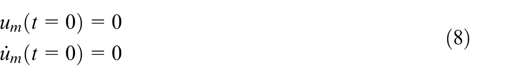
The 3D finite element model was developed using commercial finite element code ABAQUS 2020 version. The explicit solver was adopted to calculate the dynamic response of the peening process. This model aims to simulate a refined mesh region partitioned from a large cell, as shown as the red and yellow cuboids in Figure 1, respectively. The dimension of the mesh-refined region at the center of the cell is
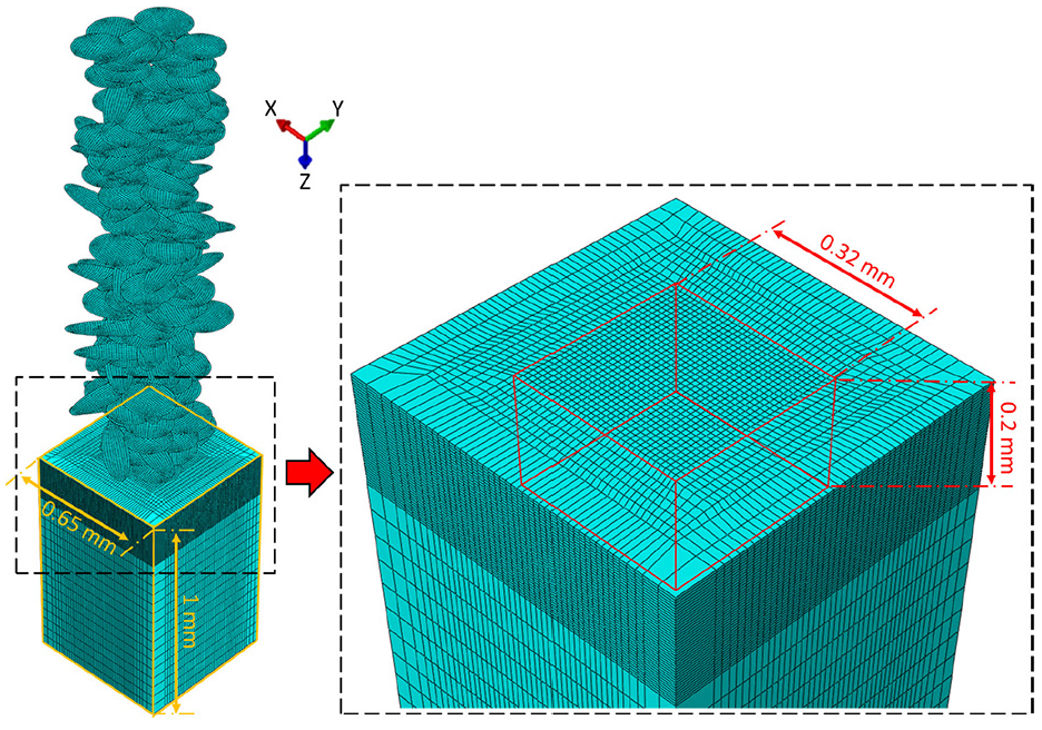
Finite element model for random orientation impacts. The yellow cuboid on the left figure is referred to as the cell and the red cuboid on the right image shows the mesh-refined region.
The coordinate system was set as same as the default coordinate of large cell which is at the center of the cell surface and z-axis along the normal direction and facing inside of the surface. The displacement boundary conditions and contact conditions applied to the model are as follows:
Encastre/fixed boundary conditions were applied to all the nodes on the bottom surface of the large cell:
Symmetry boundary conditions were applied to the opposite side boundaries of the whole cell to couple the corresponding degrees of freedom (DOFs): the normal displacements
A general contact algorithm between shots and target surface was adopted with no limit on shear stress, infinite elastic slip stiffness, and isotropic coulomb friction coefficient of 0.2.
The whole-cell was discretized using eight-node brick elements with reduced integration (C3D8R). The reduced integration element was chosen because the locking phenomena were not observed in the full integration element (C3D8), and the results from C3D8R showed no discernable difference from those using C3D8. In addition, the computational time was largely reduced without compromising the accuracy of explicit solvers. The mesh was refined at the mesh-refined region. The final element size was adopted around 0.005 mm for the top refined region of the cell after conducting the mesh convergence tests. The remaining regions of the cell were discretized using larger elements which value is around 0.02 mm. A typical model contained 121,072 elements. The media were created as rigid using four-node bilinear quadrilateral elements (R3D4) to reduce computational time. The rigid shots were modeled in the FE model using a rigid analytical surface with an equivalent point mass and an equivalent point rotational inertial (
The initial state of all material models was under a stress-free condition. The only normal impact is considered in this work, albeit changing the orientation to facilitate the different facets of irregularly-shaped media. It was assumed that the initial vertical distance between particle and workpiece is 0, that is, in contact. The collision time for each impact is 1.8×10⁻⁵ s, while the idle time between the consecutive impacts is 7×10⁻⁶ s. These values were estimated based on preliminary investigations – collision time was computed from simulations with velocity controlled media particles.
Impact model of randomized location
This paper first investigated the randomized impact location model of the peening process. The evolution of the residual stress of a smooth cell surface will be explored. In general, the impact between media surface and components surface is associated with stochastic and probabilities during the mass media finishing and peening processes. It is reasonable to involve randomization and probability density function (PDF) in the modeling to analyze individual contact areas in multi-faceted contours of the satellite media. For this study, a tub-type vibratory machine (Walther Trowal TMV175) loaded with spherical stainless steel media and three-stages blisk drum was modeled in the commercial discrete element code EDEM software (version 2020). The total simulation time was 10 s (excluded the initial 3 s for the media to reach a steady flow condition). The compressive force and pressure data for different stages of the blisk drum and media were extracted from EDEM simulation results using customized PYTHON scripts. The discrete element model was validated using the FUJIFILM pre-scale sensors, and the results were quantitatively in good agreement with the pressure patterns, as observed in the DEM model. According to the data extracted from the EDEM model for the peening process (as characterized in Figure 2), the impact force for the peening process to compare multi-faceted contours of the satellite media was set to the mean value of position 2 and 3, which was equal to 10 N. The collision time for each impact was around
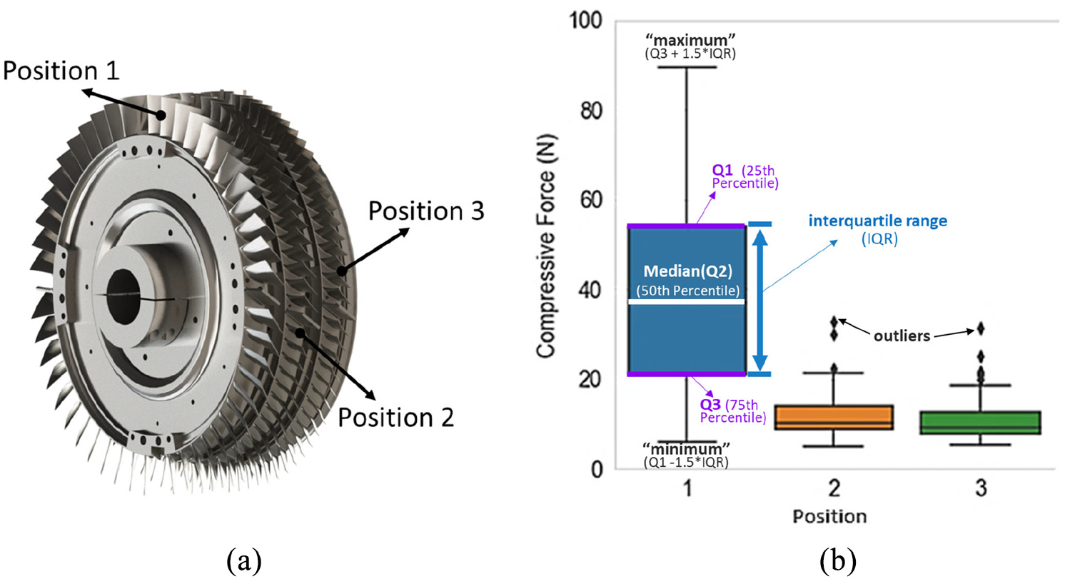
(a) Three-stages blisk drum modeled in EDEM and (b) compressive force in EDEM simulation of three-stages blisk drum, note that positions correspond to blisk stages.
It is noted that each particle impact is subsequently removed from the simulation, thus there was no interacting with the other incoming particles in the subsequent particle impacts – the overlay of particles at Figure 1 gives an overall illustration all the particles simulated. The discrete element model can directly provide the probability density distributions of impact force and consider particle to particle collisions.
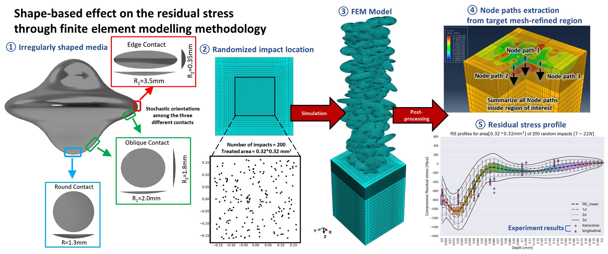
For irregularly-shaped media (ballcones or satellites) in the surface enhancement process, the different regions are shown in Figure 3(a). The whole satellite media could be classified into three different contact regions: (1) the planetary rings of satellite media could be defined as edge contact region, which contact portion is oval-like; (2) the polar regions of satellite media could be defined as round contact region; (3) other regions which are close to planetary rings and polar regions could be defined as oblique contact. The contact portion of both round contact and oblique contact are approximate, but dimensions for both are different. The dimensions for three different contact are shown in Figure 3(b).
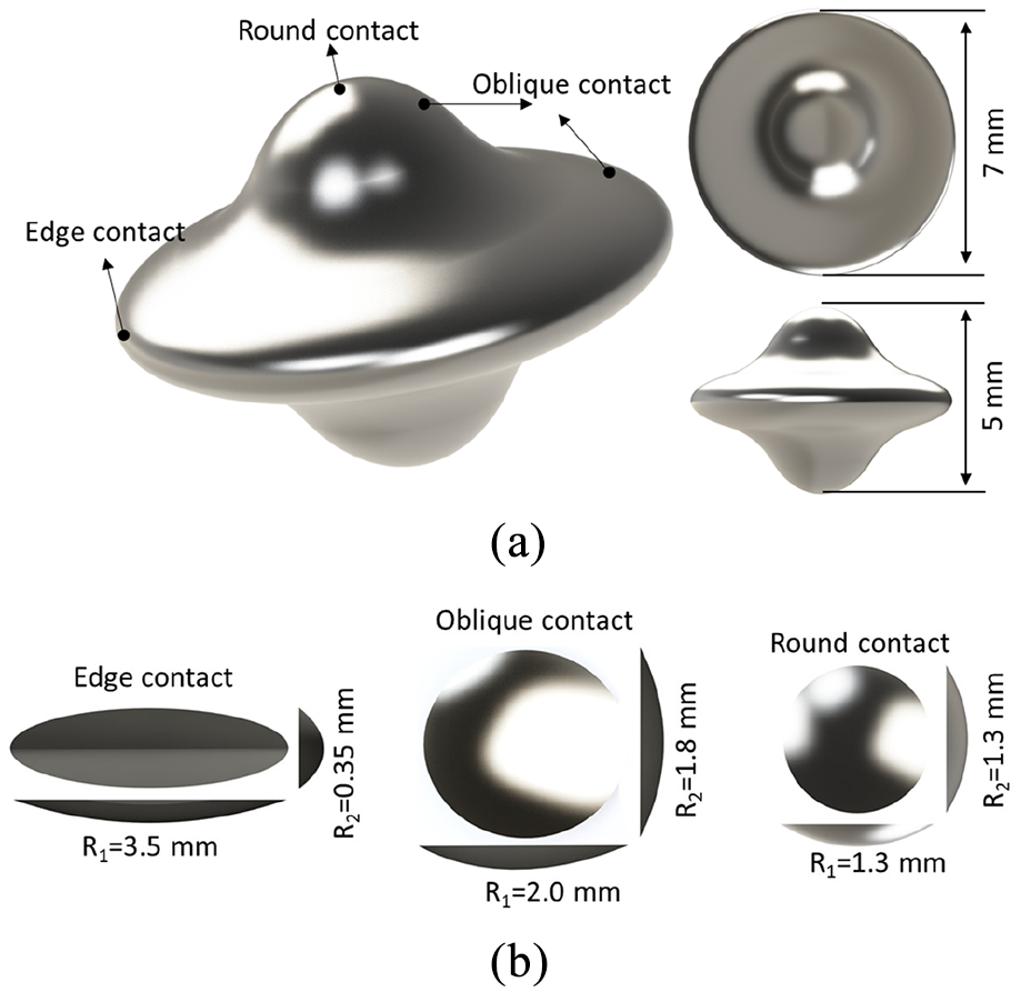
(a) Spherical media different contact types and (b) dimensions.
In order to achieve random impact, a multiple impact model is established. The stochastic locations of the media are controlled by the PYTHON code to experience a random impact on the surface of the mesh-refined region. The impact center positions of a total of 100 simulated impingements are indicated in Figure 4. The media are assigned the same tabular force values chronologically and impacted the target surface one by one sequentially.
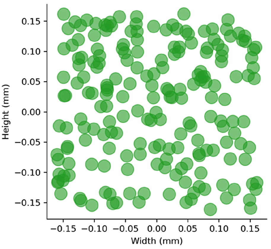
The impact positions of 100 impingements.
Impact model of randomized location, orientation, and force
In the same methodology as modeling of randomized locations, the stochastic orientations of irregularly-shaped media and contact forces applied in load module of FEM model are controlled by customized Python code to experience stochastic impacts on the surface of the target region. For each impingement, the code randomly selected one contact type among the three different contacts and then defined corresponding boundary conditions, that is, forces and locations, automatically. It is noted that the assumption for contact type probability is uniform, that is, 33.3% for each type of contact. There may be a preferred impact orientation, but there are no experiments that were done to validate this. Nevertheless, this can be an interesting future study for irregularly-shaped media in general.
According to the data extracted from the EDEM model for the peening process, the probability density function (PDF) of the compressive force was generated. The force magnitude was sampled by polling the contact force from the PDFs. The histogram of force distribution is indicated in Figure 5. To investigate the combination effect of different contact types and forces, a stochastic impact model is developed to achieve more representative simulation results for the real experimental cases.
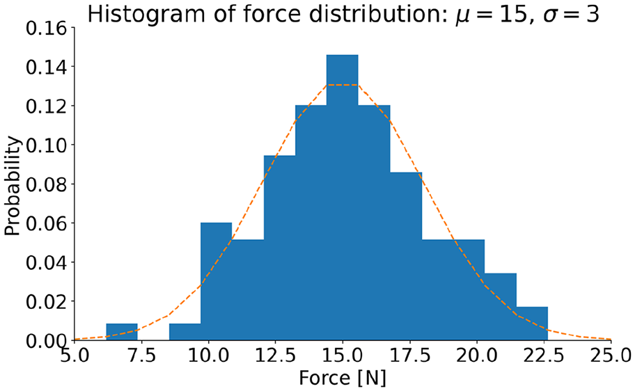
Normalized histogram and the probability density function of impact forces for the random impact model.
The contact regions of media are assigned the tabular force values chronologically and impacted the target surface one by one sequentially. An ABAQUS-PYTHON script was developed to realize these procedures.
For post-processing the results, a total of 1024 node paths in the target mesh-refined region were extracted from results of FEM model (three node paths were represented in Figure 6 as an example). The residual stress profiles were generated by extracting the residual stress component
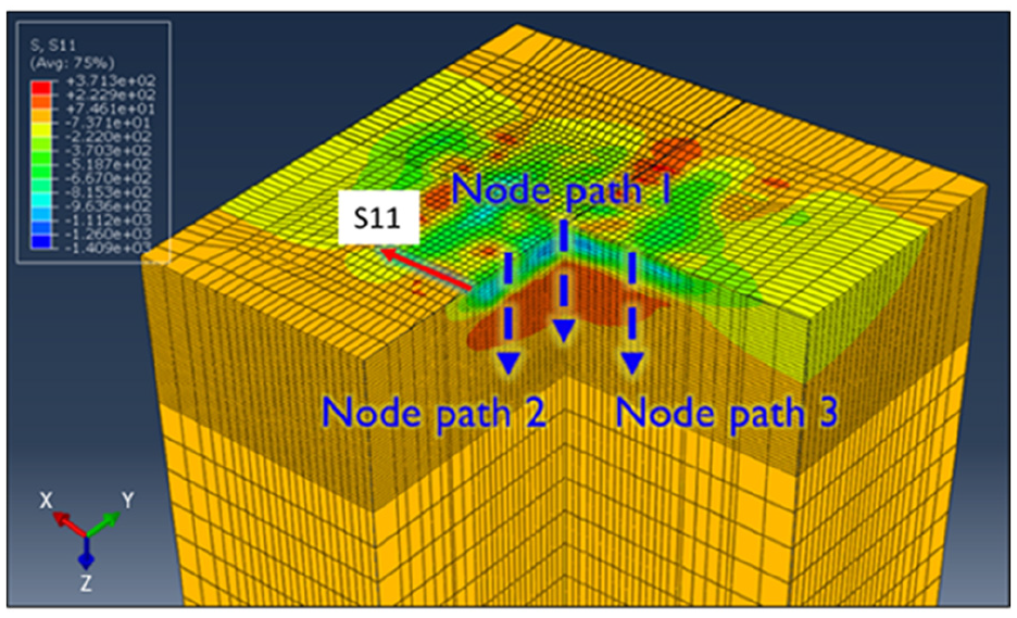
Illustration of the random impact model, node paths indicated are sample measurement paths for taking residual stress measurements with depth.
Results and discussion
A post-processing script is coded using the PYTHON language to extract the residual stress from the multiple impact models. The residual stress profile after the peening process is represented by calculating the average of the nodal residual stress at each depth over all nodes of the mesh-refined area (0.32 mm × 0.32 mm). This analysis method is employed by Gangaraj et al.
17
and Kim et al.
28
to estimate profile of residual stress distribution. The profile of residual stress distribution was computed in two in-plane perpendicular components (X and Y directions according to Figure 1). Due to the planar isotropy of in-plane residual stresses, the measurement directions were independent according to two orthogonal components. Therefore, only one direction (
The numerical residual stress profile for round contacts after 100 impacts is shown in Figure 7. It can be observed that compressive residual stresses are generated at the surface and subsurface region of the material model, which is caused by local plastic deformation. This in general happens to all the contact areas that were simulated in this study. According to the figure, about 400 MPa compressive residual stress (CRS) was created at the surface of the material. At a depth of 0.02 mm, the mean CRS rapidly increased to the maximum value of 1029 MPa. After the max CRS location and deeper into the component, the mean CRS sharply decreased and eventually changed from compressive to tensile state as at around 0.046 mm depth. This depth is referred to as the depth of the compressive zone (DoCZ). It was shown that the tensile residual stress increased to the maximum tensile residual stress (TRS) of 157 MPa at a depth of 0.055 mm. Deeper into the material, the TRS magnitude slowly decreased to the initial equilibrium state.
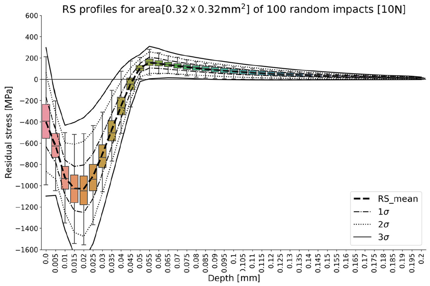
Boxplot and standard deviations of residual stress profile for round contact.
On a similar plot, Figure 8 shows the CRS profile with edge contacts after 100 impacts. The surface residual stress was about the same as with the round impact at 391 MPa. The maximum CRS value was measured to have mean value of 870 MPa, which is significantly lower than with the round impacts. Moreover, the DoCZ is found at 0.033 mm, about 0.013 mm shallower than the round impacts model.
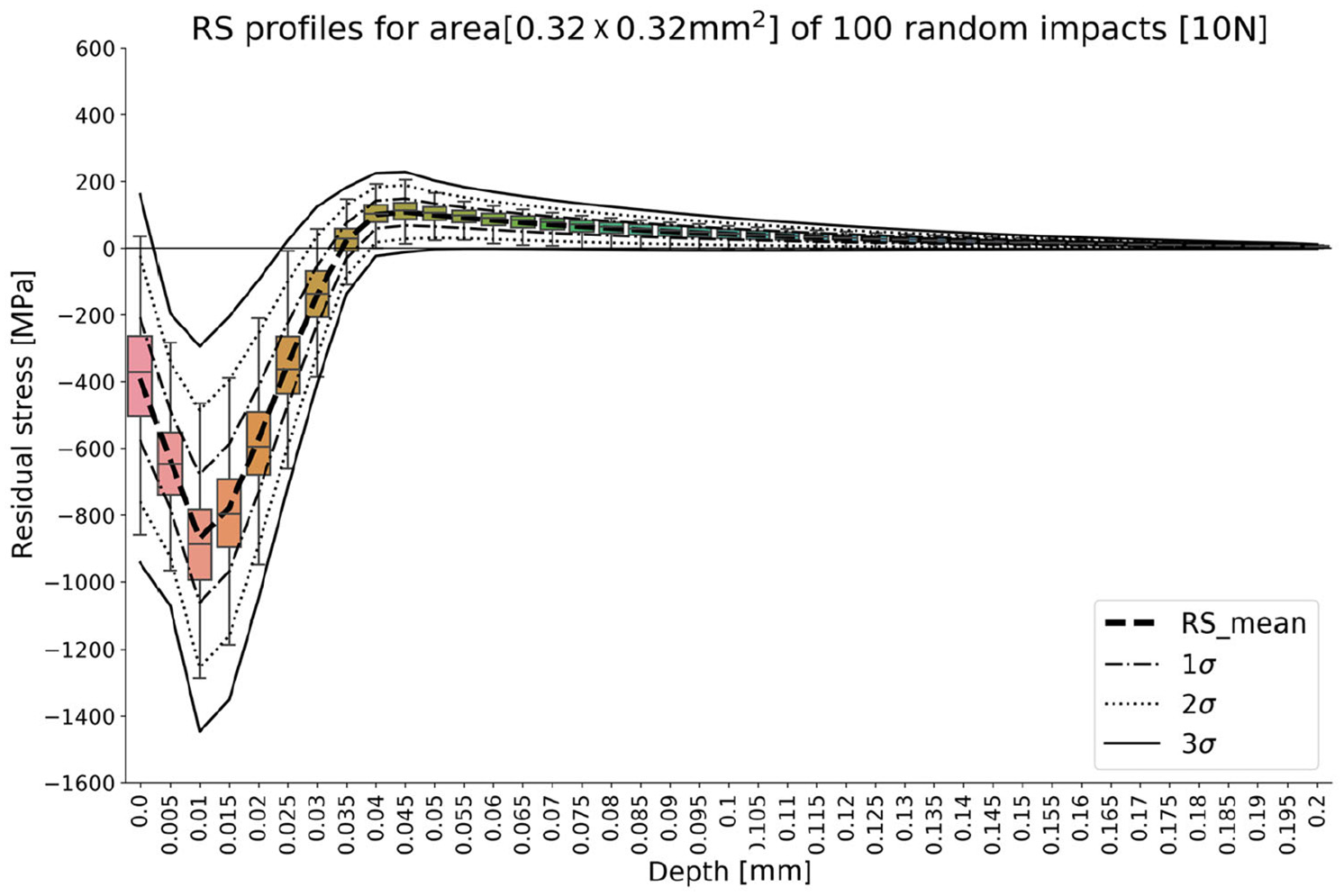
Boxplot and standard deviations of residual stress profile for edge contact.
The thirrd contact type that is simulated is the oblique contact, on which the residual stress profile is shown in Figure 9. Surface CRS and maximum CRS values have very low magnitudes – 114 and 488 MPa, respectively, as compared with the round and edge contacts. Interestingly, the DoCZ was found to be in between the round and edge type contacts at 0.037 mm.
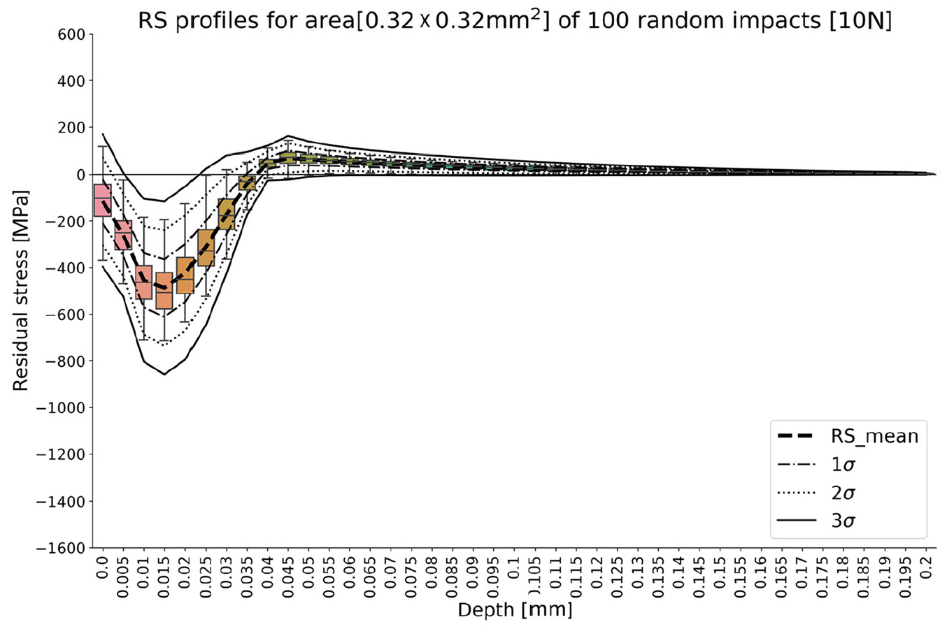
Boxplot and standard deviations of residual stress profile for oblique contact.
Finally, the residual stress profile for random orientation contacts after 100 impacts is shown in Figure 10. The surface residual stress was 577 MPa, which was larger than all of the single contact-type simulations that were discussed previously. The maximum CRS value is 914 MPa, which was in between the round and edge contacts. The DoCZ was found to be at a depth of 0.065 mm, which was significantly deeper than the individual contact types. To recall, the single contact type that has the deepest DoCZ was that of round contacts, at 0.046 mm.
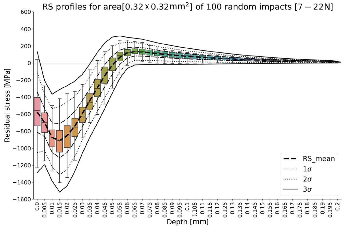
Boxplot and standard deviations of residual stress profile for impact model of randomized orientation and force.
Figure 11 compares the single contact-type and random contact-type simulations in a single plot. In summary, the irregular shaped media contact with the target material surface can cause significantly different residual stress profiles due to the differences of media contact geometry dimensions. It is worth pointing out that the larger contact area between media surface and target material surface creates a lower value of maximum compressive residual stress. Recall that the edge contact portion of planetary rings of satellite media is oval-like and asymmetric and the aspect ratio for the two orthogonal directions of edge contact cross-section (see in Figure 3(b)) is about 3.3. Table 3 summarizes the aspect ratio and contact area for each contact-type and the resulting max CRS and DoCZ after 100 random location impacts. An observation from this table is that smaller contact area induces a higher value of the max CRS, while the DoCZ appears to be controlled by the aspect ratio, where a higher aspect ratio resulting to a shallower DoCZ.
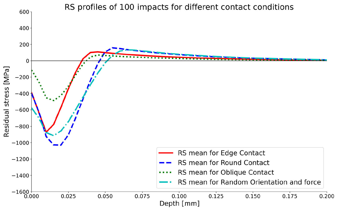
Comparison of three different contact locations.
Summary of random impact model with different contact types.
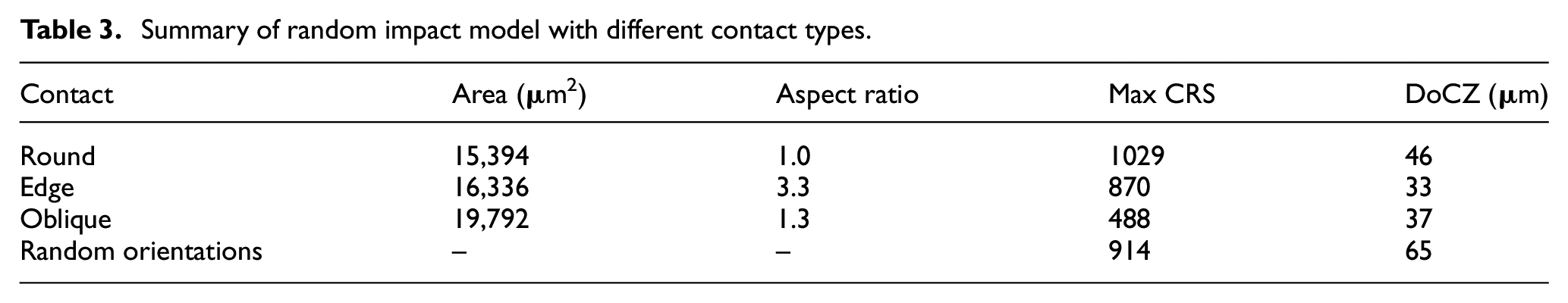
Figure 12 illustrates the target’s residual stress profiles after 25, 50, 75, 100, 125, 150, 175, and 200 impacts. It is noted that there is a larger difference in the RS profile in the earlier stages of the impacts, that is, the difference in 25 and 50 impacts is larger than the difference between 175 and 200 impacts. This is in-line with the understanding that the components plastically deform and work-harden as the number of impacts increase. Furthermore, the CRS region grew wider and sank deeper, that is, increased maximum compressive stress and depth of compressive zone (DoCZ). As suggested by the trend, the compressive layer would be saturated at high levels of coverage.
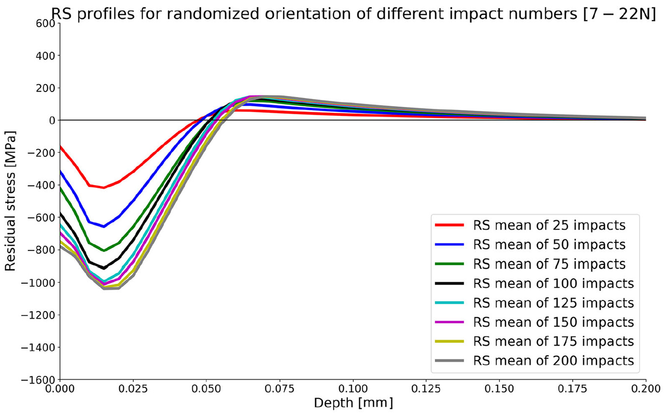
Comparison of different no. of impacts for randomized orientation.
The maximum compressive residual stress (CRS) and the depth of compressive zone (DoCZ) was taken from the residual stress profiles from Figure 12 and is summarized in Figure 13. It is worthy to note in Figure 13(a) that the mean value of maximum CRS for the target area was almost saturated after 125 randomized impacts. As the number of impacts kept increasing, the growth of the mean value of the maximum CRS was minimal. In contrast, the growth trend of the depth of compressive zone was still growing linearly with more impacts. A linear regression model was fitted using the data of zero-crossing depth, as shown in Figure 13(b). Until 200 randomized impacts, the DoCZ was still increasing linearly and was not yet saturating. Thus, increasing impact number not far from the simulated number of impacts would still broaden the CRS region.
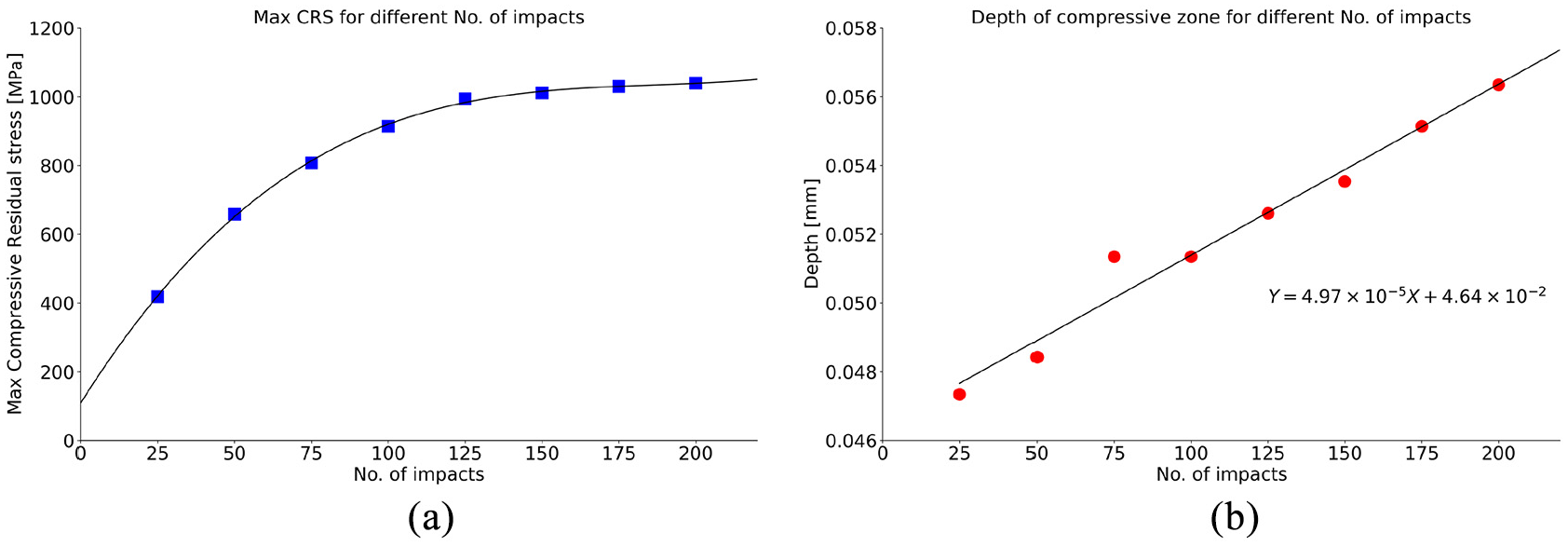
Effect of No. of impacts: (a) maximum CRS and (b) Zero-crossing depth.
The Inconel 718 samples studied in experiments were in the state of initial compressive stress. Due to the temperature difference on the surface and inner layer of material when it experiences the heating and cooling process, the initial stress is generated on the surface and sub-surface of samples during manufacturing. Based on the initial stress state data, the FEM model was modified by inducing a similar amount of initial stress to achieve a pre-stressed condition for the target model (as shown in Figure 14(a)). The star and triangle markers were experimental residual stresses measured by XRD. After introducing pre-stressed conditions to the FEM model, the residual stress profile of the impact model of randomized orientation and force was corrected. The comparison between experimental residual stress data and numerical residual stress profile after 200 impacts is shown in Figure 14.
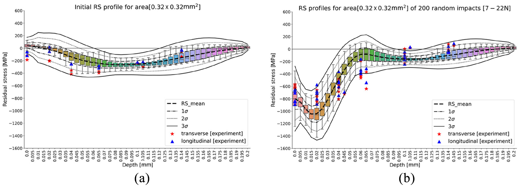
Comparison of the random impact model in pre-stress condition with experiment data in the longitudinal and transverse direction: (a) the initial stress condition of the material model and (b) the CRS profile after random impact.
Since the mean values of the surface compressive residual stress (CRS) and maximum CRS for the target area are almost saturated after 125 randomized impacts, the percentage differences of mean stress values between simulation and measured residual stresses are less than 34% at surface up to a depth of 20 μm in both longitudinal and transverse directions, and most measured stress data are within 3-sigma of the FEM results, as demonstrated in Figure 15. The percentage difference near the depth of 60 μm is 309.4% and some data points are outside of the 3-sigma lower limit – this may be because the depth of compressive zone (DoCZ) is still growing linearly after 200 randomized impacts. It is worth to note that the DoCZ will broaden by increasing the impact number, and the percentage difference between measured and simulated data will be reduced simultaneously, especially for the region between 40 and 80 μm.
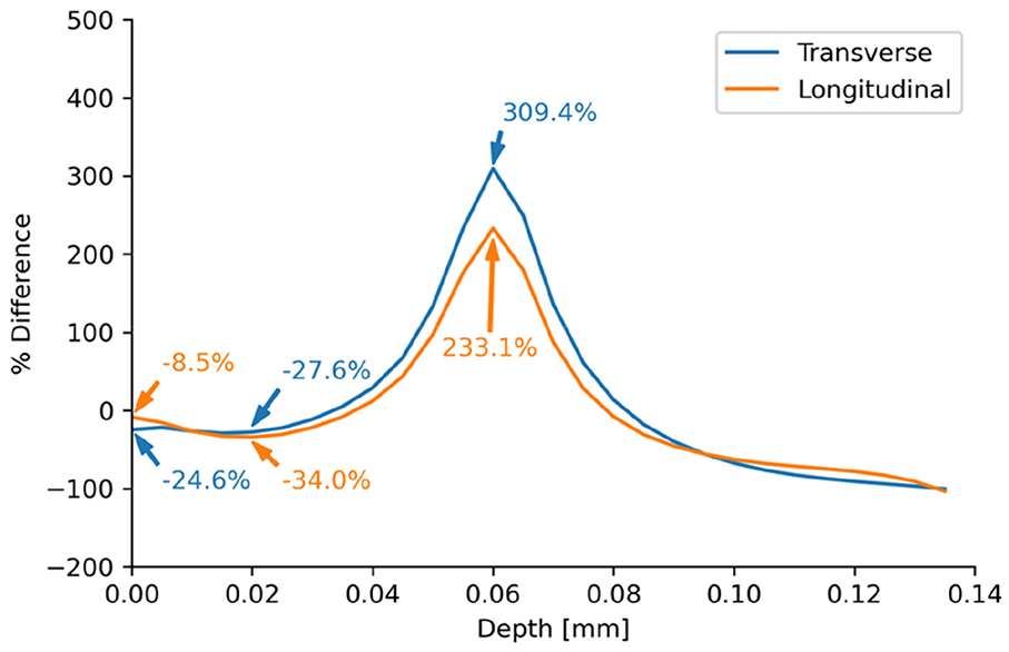
Percent difference between measured RS and simulated RS from random impact simulation.
A comparison of the surface material before and after vibropeening is shown in Figure 16. It is shown that the electric discharge machining (EDM) melt deposits or globules are flattened after vibropeening. The assumption of the FEM simulations does not consider the roughness of the actual EDM surface, and the resulting plastic deformations at the surface range from heights of −0.3 to 0.6 μm. These are very small as compared to the actual depth of residual stresses that are formed, that is, >40 μm. Nevertheless, Figure 16(c) shows that most of the peened area are covered with positive deformations, ultimately resulting to those residual stresses beneath the surface.
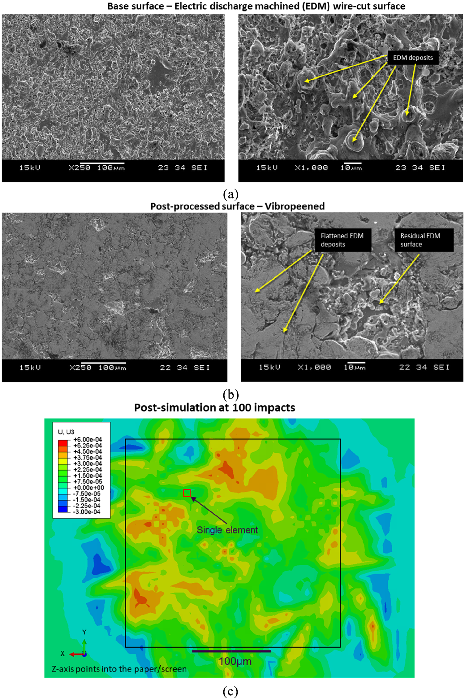
SEM images of (a) pre-vibropeened and (b) post-vibropeened surfaces of Inconel coupons at 250× and 1000× magnification, and (c) FEM simulation showing normal deformation (z-axis) contour plot of random impact model after 100 impacts.
Conclusion
In practice, most of the finite element model for multi-impact simulations developed recently did not focus on the influences of irregular media shapes on stress profile evolution but only on the general spherical media shape. Building confidence through simulation is important such that the benefits in terms of inducing residual stress during the surface enhancement process is maximized even before media shape selection and procurement. A finite element-based model methodology was presented for a parametric study of vibratory surface enhancement with irregularly-shaped media. This model was then used to investigate residual stress profiles within a treated area of an Inconel component. The key findings of the study include:
A finite element-based model of multi-orientation random impact in the peening process was able to predict the residual stress profile. The numerical results were in good agreement with the experimental residual stresses measured by XRD, with a max percent difference of 34% up to 20
Due to the differences of geometry dimension, the irregularly-shaped media can establish random contacts with the target material surface, and hence cause significantly different residual stress profiles.
The larger contact area between media surface and target material surface creates lower values of maximum compressive residual stresses, as demonstrated by the round and oblique contacts, with a plane-averaged maximum CRS value of 1029 and 488 MPa respectively. This is because of the larger media surface area that comes in contact with the component, thus a less concentrated pressure distribution.
The aspect ratio for the two orthogonal directions of the contact cross-section area also has an influence on residual stress distribution. It appears that a higher aspect ratio is related to a shallower DoCZ. In a comparison with edge and oblique contacts, while the max CRS of the oblique-type contact is smaller than the edge-type contact by 382 MPa, while the DoCZ is slightly deeper by 4
The maximum CRS increase exponentially with respect to impact number, while the depth of compressive zone (DoCZ) increased linearly between 0 and 200 random impacts.
It was found from the micrographs that the surface of a vibropeened component is characterized by the flattened melt deposits that originated from a previous cutting process, though these surface deformations only affect a relatively shallow region, that is, <1 μm beneath the surface, as compared to the actual depth of residual stresses that are formed, that is, >40 μm.
The results in this paper showing the effect of a multi-faceted media surface enables us to understand its effects locally on the residual stress of a component. In an industrial application sense, this proves the beneficial effects of multi-faceted media in surface enhancement processes despite its shape differences to previously reported media shapes, that is, spherical, for vibropeening and supports its continued use for hard to reach corners of a component. To a certain extent, the finite element models involved randomization and stochastic methods to predict the residual stress quite well in analyzing surface contact in multi-faceted contours of the satellite media. The simulation methodology for current modeling work can be transferred smoothly to the future study of surface finishing effects of the vibro polishing process associated with variations of media shape.
Footnotes
Appendix
Acknowledgements
The authors would like to acknowledge Kunal Ahluwalia and Marcus Ang from the Advanced Remanufacturing and Technology Centre (ARTC) for their help in providing the XRD measurements of Inconel 718 coupons.
Declaration of conflicting interests
The author(s) declared no potential conflicts of interest with respect to the research, authorship, and/or publication of this article.
Funding
The author(s) disclosed receipt of the following financial support for the research, authorship, and/or publication of this article: This work was conducted within the Rolls-Royce@NTU Corporate Lab with support from the National Research Foundation (NRF) Singapore under the Corp Lab@University Scheme.