
Abstract
The main objective of this work was to evaluate the influence of turning parameters on the generation of residual stresses in AISI 1045 steel bars. Therefore, effects of four main parameters as feed rate, cutting velocity, tool nose radius, and rake angle were analyzed. Residual stresses investigation through X-ray diffraction (XRD) was carried out at different depths (surface, 5, 10, 20, 50, and 75 μm). As the samples showed distinct roughness patterns with variable amplitude and shape, and based in a previous work, samples were classified in two main groups accordingly with surface finishing (regular and irregular). The current results showed that feed rate and cutting speed played the major influence on residual stress distributions. Moreover, the tool nose radius affected surface residual stresses, whereas the rake angle did not significantly change it. Finally, samples could be divided in two residual stress groups, showing a direct relation of surface finishing quality and residual stresses.
Introduction
Quality control is essential to any manufacturing process. Progress in machining technologies and production routes for generating excellent surface quality have been one of the driving forces to develop high performance manufactured products. 1 During turning processes, the control of surface roughness, geometry, and thermally affected region can be a key to the surface integrity.2,3 In general, surface integrity describes the physical state and features of a given surface concerning performance. Concerning machining, surface integrity can be divided into three main aspects, which include surface roughness, residual stress, and white layer formation. 4 Surface topography and finishing are commonly associated with roughness analysis, while beyond surface characteristics, microstructure, and mechanical properties may be related to residual stresses. 5
Residual stresses generation and modification in machined components are a response to mechanical and thermal events, which occur in the near surface region during machining. Residual stresses can be tensile or compressive, and the modified layer can be shallow or deeper (up to 100 μm), according with the machining parameters, workpiece material, and tool geometry.6,7 In this frame, X-ray diffraction (XRD) has been often employed for residual stress analysis in turning process.1,7–14 Turning parameters that have presented a more considerable influence on residual stresses are tool nose radius, cutting speed, and feed.7–11 An adequate rake angle choice has been reported to generate compressive residual stresses below surface and, in some situations, extend these values to deeper regions.1,9,12 Moreover, cutting depth was reported to have low to none influence in residual stresses modification. 7
Residual stresses evaluation depends on the measuring technique used, perhaps using the hole drilling method, for example, surface values up to about 50 µm will be very difficult to resolve. Therefore, in this work, high resolution X-ray diffraction (XRD) residual stress analysis associated with electrochemical layer removal were employed to assess surface as well as deeper layers. Thus, this work aimed at investigating the influences of turning parameters on generated residual stresses of AISI 1045 steel bars, by varying feed rate, cutting speed, tool nose radius, and rake angle.
Materials and methods
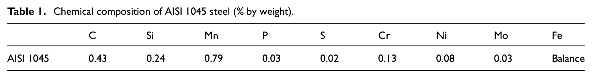
AISI 1045 steel bars manufactured by a combined drawing process were used in the current work. The bars had 20.65 mm of diameter and 400 mm of length, with the chemical composition given in Table 1. A characterization of the material properties, including the resulting residual stresses from the drawing process has been investigated by our group in previous works, so that the initial state of the material for the present work is well known, and these details can be found in.15–19; however, the present evaluation emphasis on turning parameters effects in residual stress states.
Chemical composition of AISI 1045 steel (% by weight).
The first stage of this work began with roughness and finishing evaluations in sixteen samples, with different turning parameters (reported in Biasibetti et al. 20 ). Based on these findings, seven samples, which potentially should have residual stress modifications after turning, were selected for the current investigation.
A portable roughness device (Mitutoyo SJ-210) was employed for the prior roughness analysis. The analysis of surface finishing by roughness profiles, combined with roughness parameter Rz (mean of partial peaks) was used to classify finished samples in two groups named as regular (R) and irregular (I), as illustrated in Figure 1. The roughness results are detailed in Biasibetti et al. 20 An example of the regular surface finishing is presented in Figure 2(a), whereas an irregular finishing can be observed in Figure 2(b).
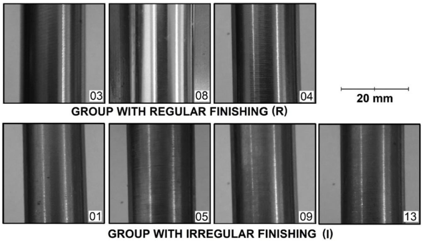
Samples grouped according to their surface finishing quality.
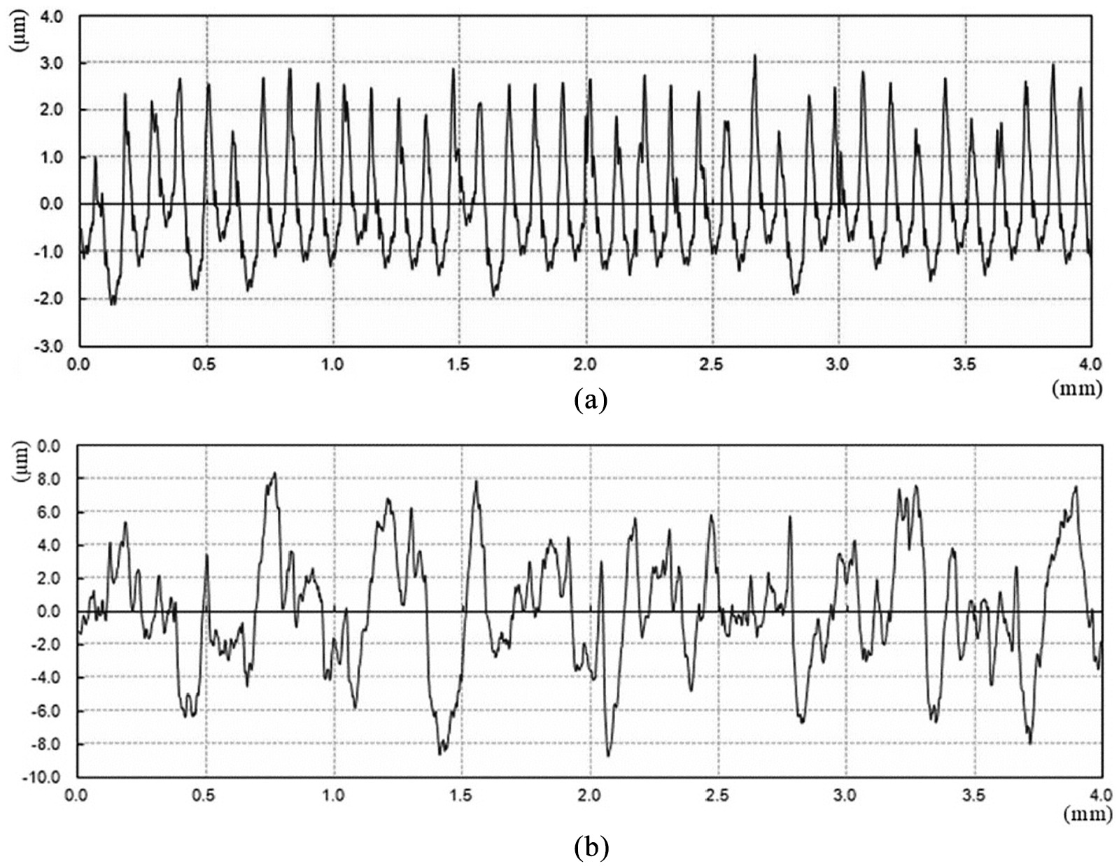
Roughness profiles: (a) sample 03 (250 m/min, 0.1 mm/rev, 0.4 mm, 7°) shows a regular surface finishing and (b) sample 13 (150 m/min, 0.1 mm/rev, 1.2 mm, –6°) presents an irregular surface finishing.
Turning process
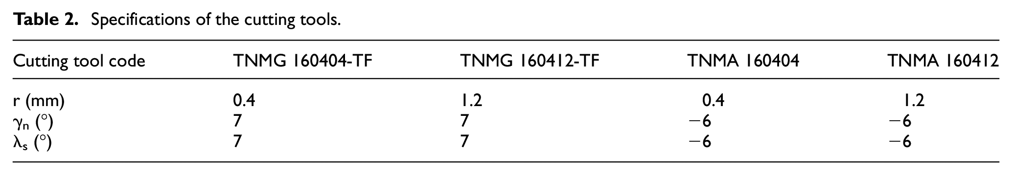
A CNC Romi 30D lathe was used for turning the samples. At first, the samples were turned with a 0.4 mm cutting depth (d) to remove any heterogeneity that might have been present near the surface. Then, a second pass with a 0.1 mm depth was executed to produce the final surface. All the samples were submitted to dry turning. Table 2 presents each cutting tool in the MTJNR turning support. The following angles were identical: κr of 93°, κr′ of 27°, and αn of 6°. Besides, other cutting angles are presented in Figure 3. Furthermore, the turned samples are described in Table 3.
Specifications of the cutting tools.

Schematic sketch of a turning operation and the main angles: (a) cutting edge plane and (b) plane normal to cutting edge. 21
Samples for residual stress analysis, turning parameters, and surface finishing.
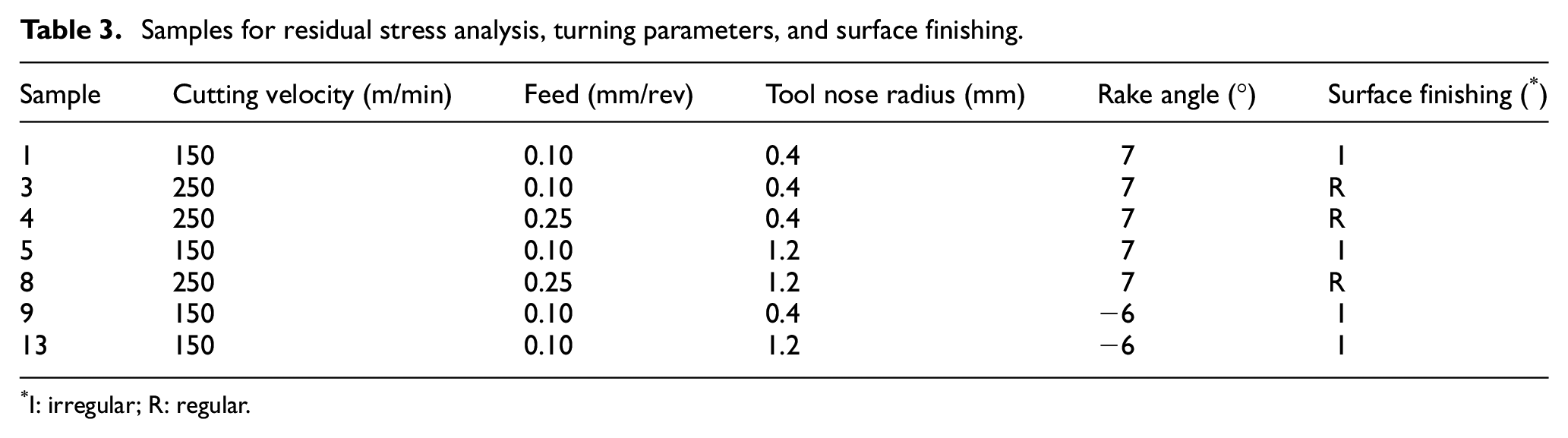
I: irregular; R: regular.
X-ray diffraction for residual stress measurements
For the residual stress analysis, a GE Seifert Charon-M Research Edition® diffractometer equipped with Cr-Kα radiation X-ray tube and a Meteor 1D detector was employed. In the incident diffraction beam a 2 mm aperture was used. The side inclination in Bragg Brentano condition was used to record the lattice distance variation for the {211}-lattice planes at 2θ reference angle of 156.08° and for 21 different ψ (inclination) angles distributed in the positive and negative sides. The measured range in 2θ was from 147 to 166° in steps of 0.2°, with 10 s. The sin2ψ method 22 was employed using following elastic constants: poison ratio of 0.28, Young’s modulus of 220 GPa, and elastic constants s2 and –s1 were taken to be equal to 5.81E−6 and 1.270-6 MPa−1, respectively. The slope of a linear regression through the measured data provided the residual stress value for the defined Φ direction. The standard deviation of the calculated residual stress values of the experimental data comes from the linear deviation of the lattice distances as function of sin2ψ (for the 21 ψ-angles).
Furthermore, for investigation of the residual stresses as a function of depth, an electrochemical etching removal was adopted. The samples were immersed in a solution of 34 vol.% H2SO4 and 42 vol.% H3PO4 in 24% distillate water. The voltage applied was 3.5 V between sample and reference electrode. Next, the sample diameter changes were checked for verifying the new depth to be analyzed. The residual stress evaluation was done for two directions, the feed (axial direction (f)) and cutting velocity (tangential direction (v)), as displayed in Figure 4. Thus, residual stresses were analyzed in seven selected samples at varying depths (surface, 5, 10, 20, 50, and 75 µm). The first analyzes were done at the surface (no material removal) with ten measurements, showing good repeatability (no significant variation between them). Later, after the material removal, it was decided to make three measurements (also due to their repeatability) for each new depth to be measured. The residual stresses were corrected for the relaxation due to material removal employing an adaptation of Moore and Evans method. 23 Finally, samples for residual stress measurements, turning parameters, and surface finishing are summarized in Table 3.
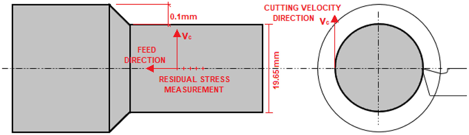
Schematic drawing showing residual stress measurements location and their directions (feed and cutting velocity).
Microstructural analysis
Microstructural analysis of samples was carried in an optical microscope Olympus GX51 model. Two samples were selected for the analysis based on prior roughness and residual stress states. These two representative samples have different surface finishing levels achieved by turning (regular (R) and irregular (I)), samples 03 and 09, respectively. Then, the turned surface areas were ground, polished and etched by a 2% Nital etchant solution.
Results and discussion
Effects on residual stresses were analyzed to allow an understanding of each turning parameter individually. Therefore, comparisons between distinct samples were done for each parameter investigation (feed rate, cutting velocity, tool nose radius, and tool rake angle).
Feed rate (f)
Figure 5 presents residual stresses as a function of feed rate. The effects from turning parameters of samples 03 (250 m/min, 0.1 mm/rev, 0.4 mm, 7°) and 04 (250 m/min, 0.25 mm/rev, 0.4 mm, 7°) were analyzed. At the surface, the residual stresses (in the feed direction) of sample 03 was 303.3 MPa, which is around half of the residual stress (629.6 MPa) achieved by the sample 04. Increasing feed rate (from 0.10 to 0.25 mm/rev) led to a significant increase in surface residual stresses. In the cutting direction, the sample 03 reached a lower residual stress value (445.7 MPa) than the sample 04 (585.7 MPa), but the difference between them was small. Therefore, it is seen that a change in feed rate affects more the residual stresses in feed than in cutting direction.
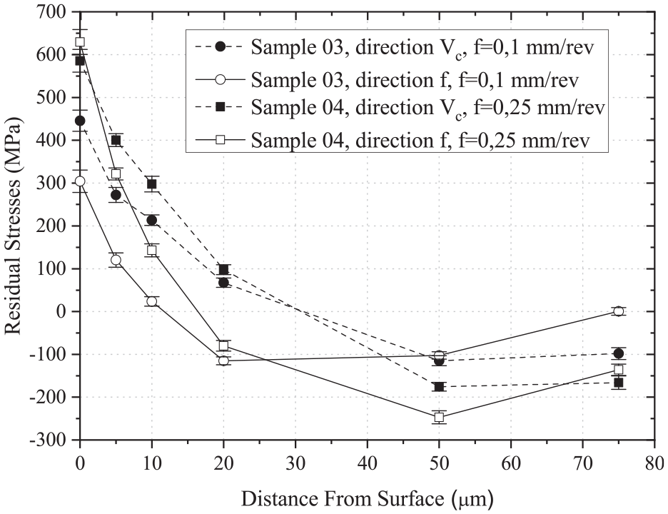
Comparisons between residual stresses of samples 03 and 04 for the feed and cutting velocity directions.
Feed rate increase resulted in higher tensile residual stresses at the surface and near-surface in both directions (feed rate and cutting), but with somewhat greater values for the cutting direction. Higher feed rates raise the feed force and generate an increasing heat input into the shear zone. As observed in Figure 5, the affected region changed from about 10 to 20 µm as the feed rate increased. For higher depths, the stresses become compressive due to the cold plastic deformation with a minimum at around 50 µm. Therefore, the feed rate had a strong effect in residual stresses at the surface and near-surface (up to 20 µm depth) in both directions. For deeper regions (below 50 µm), the residual stresses were only slightly affected by an enhancement in the feed rate. Similar findings with regard to the feed rate were reported elsewhere.7,9,11,12
Cutting velocity (v)
Figure 6 shows residual stress of sample 01 (150 m/min, 0.1 mm/rev, 0.4 mm, 7°) and 03 (250 m/min, 0.1 mm/rev, 0.4 mm, 7°). At the surface, the residual stresses in the cutting direction was considerably lower in sample 01 (185.8 MPa) in comparison to sample 03 (445.7 MPa). Therefore, an increase in cutting velocity (from 150 to 250 m/min) promoted superior tensile residual stresses at the surface. On the other hand, in the feed direction, the residual stresses were 260.6 and 304.3 MPa, respectively. At depths below the surface (up to 50 µm), a small influence of cutting velocity on residual stress change was noticed. Thus, it was observed that the cutting velocity plays the most significant role in residual stress modification at the surface.
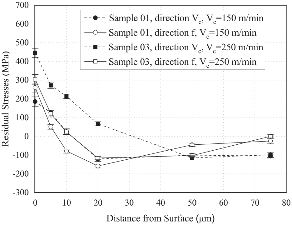
Comparisons between residual stress of samples 01 and 03 in the feed and cutting velocity directions.
Cutting velocity enhancement caused higher tensile residual stresses in cutting direction, while this increase shows no substantial influence in residual stress for the feed direction. Some authors9,11,24 found a similar cutting velocity influence on residual stresses. On the other hand, 25 verified an opposite effect of the cutting velocity in residual stresses at higher cutting velocity (500–750 m/min) meaning that, lower tensile residual stress takes place when the cutting velocity is increased. The latter phenomenon was not verified herein due to the relatively low cutting velocities applied. This effect is expected because as cutting speed increases, more heat can be generated in the shear zone and cannot be conducted away during the truly short time in which the metal passes through this zone. As the dependence of temperature and cutting velocity is strong, the local yield stress is decreased. 26 Therefore, a domination of thermal effects is seen, resulting in high tensile residual stresses with increasing cutting velocity.
Tool nose radius (r)
The comparison of sample 01 (150 m/min, 0.1 mm/rev, 0.4 mm, 7°) with 05 (150 m/min, 0.1 mm/rev, 1.4 mm, 7°), sample 04 (250 m/min, 0.25 mm/rev, 0.4 mm, 7°) with 08 (250 m/min, 0.25 mm/rev, 1.2 mm, 7°), and sample 09 (150 m/min, 0.1 mm/rev, 0.4 mm, −6°) with 13 (150 m/min, 0.1 mm/rev, 1.2 mm, −6°) allowed to verify the influence of an increase in the nose radius (from 0.4 mm to 1.2 mm) on the residual stresses. It should be noted that the samples 01, 04, 05, and 08 were turned with a positive rake angle (7°), whereas samples 09 and 13 were turned with a negative tool rake angle (−6°).
Figure 7 presents the residual stresses at the surface. When the nose radius was increased from 0.4 mm to 1.2 mm (samples 01–05 and 04–08), residual stresses decreased. Then comparing sample 09 with 13, an increase in the residual stresses was observed at the surface.
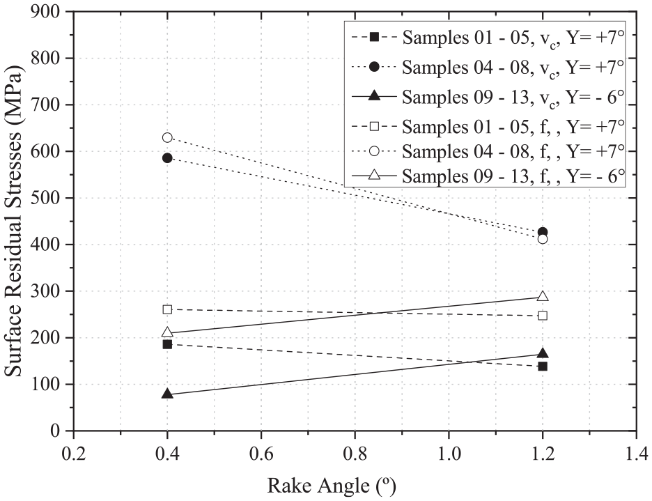
Effects of tool nose radius and rake angle in surface residual stresses.
Therefore, for the positive rake angle (γ = +7°), a reduction in tensile residual stresses was observed when the nose radius was increased, while the same increment of nose radius for a negative rake angle (γ = −6°) led to a residual stress increase. In Gunnberg et al. 9 it was reported a similar influence of rake angle and nose radius in residual stresses. Furthermore, Capello 7 also verified similar outcomes, a nose radius raise reduces tensile residual stresses in the surface, but his work considered only positive rake angle. As pointed out by Jacobus et al. 27 the generation of residual stresses in machined components can be explained as follows: at the surface of the workpiece, the main effects on residual stresses generation comes from the interaction between the total strain and depth of the heat-affected region. Thus, the total strain in the layer affected by a machining process can be described as the sum of an elastic, plastic, and thermal component.
Rake angle (γ)
Rake angle effect in residual stresses was evaluated by comparing samples 01 (150 m/min, 0.1 mm/rev, 0.4 mm, 7°) with 09 (150 m/min, 0.1 mm/rev, 0.4 mm, −6°), and sample 05 (150 m/min, 0.1 mm/rev, 1.4 mm, 7°) with 13 (150 m/min, 0.1 mm/rev, 1.2 mm, −6°). Therefore, Figure 8 displays the residual stresses in the feed direction. Then, high tensile residual stresses (up to around 300 MPa) were noted at the surface. Also, one can see that the residual stresses in the cutting direction had similar behavior as observed in feed direction. Therefore, there was no significant influence of rake angle (from −6° to +7°) on residual stress variations as a function of depth (from 20 µm to deeper regions).
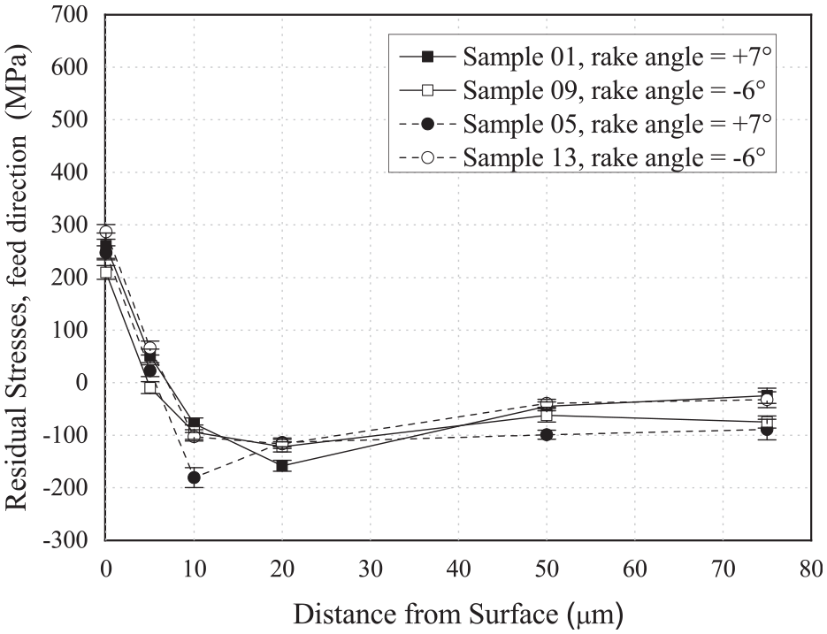
Comparisons between residual stresses of sample 01 with 09 and sample 05 with 13 in the feed direction.
Dahlman et al. 12 studied the rake angle effect on residual stresses. The rake angle was −6° to −61°, where it was found that a more negative rake angle generated compressive residual stresses below the surface. In addition, the behavior described by Dahlman et al. 12 was not observed in the current work possibly due to rake angle values that were close (−6° and +7°) and their consequences in residual stress were not as strong as those from other turning parameters. Therefore, the use of so close rake angles did not induce differences in residual stress distributions. Thus, small differences in rake angles do not lead to significant changes in thermal loads or plastic deformations and, consequently, in residual stresses.
Surface finishing influence on residual stresses
Residual stresses of samples 03, 04, and 08 (regular surface) were compared to those of the samples 01, 05, 09, and 13 (irregular surface), thus presenting the surface finishing influence on residual stresses. These results are shown in Figure 9 for feed direction and in Figure 10 for cutting direction. Then, the dashed lines are used for the residual stresses in regular surface finished samples, while solid lines for the irregular ones. In the surface (up to 20 µm depth), the regular finished samples showed greater tensile residual stresses than the irregular ones. Still, in the regular samples at 50 µm depth (feed direction), a high compressive residual stress value (−250 MPa) was observed.
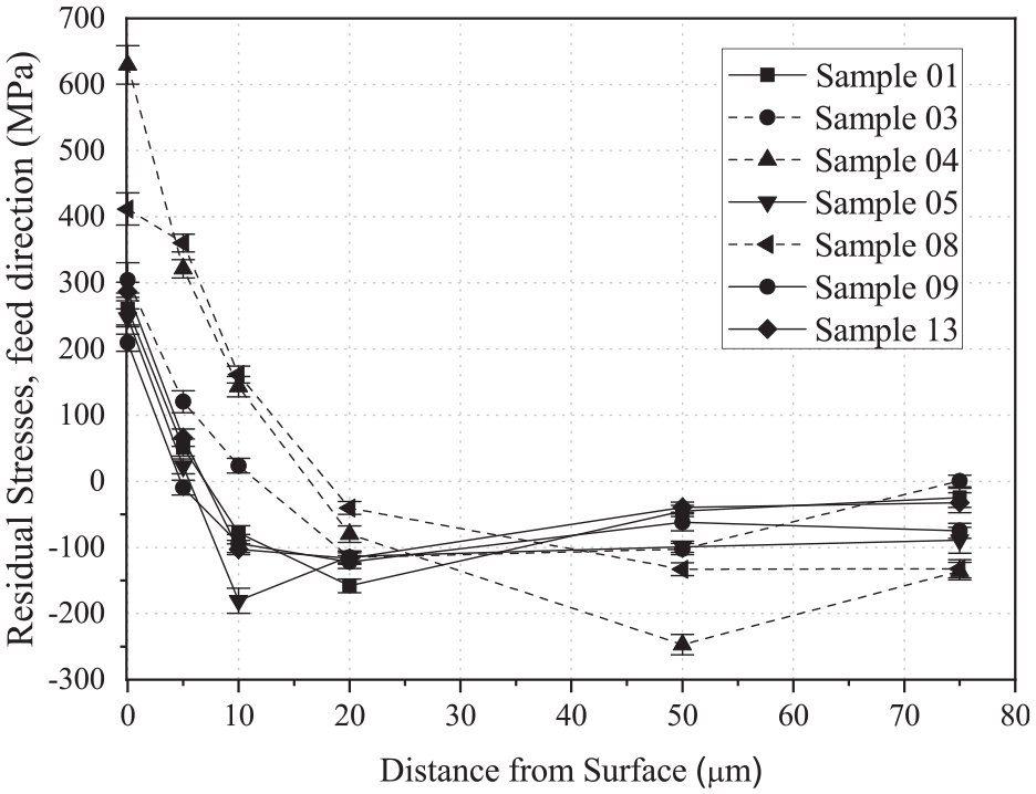
Comparisons between residual stress of samples 01, 05, 09, and 13 versus 03, 04, and 08 in the feed direction.
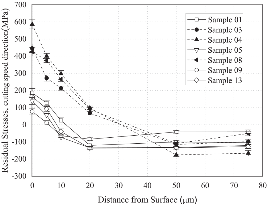
Comparisons between residual stresses for samples 01, 05, 09, and 13 versus 03, 04, and 08 in the cutting direction.
As well known, surface integrity is strongly affected by the turning process. One of the major influences on that are the residual stresses of AISI 1045 steel which have a direct relation to fatigue resistance and premature failure.28,29
High tensile residual stresses were observed in samples 03, 04, 08 (cutting direction), and in samples 04 and 08 (feed direction). These samples were turned with higher feed rates (samples 04 and 08) or cutting velocities (samples 03, 04, and 08). For deeper distances from surface, below 50 µm then the effects of machining start to vanish and all samples followed the same tendency with no large alteration in residual stress, as similarly noticed by several other authors.12,24,29,30
In the present work, a higher tensile residual stress value of 629 MPa was found at the surface. This value is similar to the results from Capello 8 (in a hardened 1045 steel) and lower than the ones found by Cabrera et al. 11 for a normalized 1045 steel. Both works8,11 considered AISI 1045 bars turned with a feed rate of 0.25 mm/rev and other parameters similar to those adopted here. The previous manufacturing process may explain these variations in the results. In refs.7,9 it was indicated that the cold work could influence residual stresses of turned specimens. Finally, for the surface integrity, as tensile stresses are critical, the highest surface residual stress (629 MPa) may lead to a high effective stress (residual stress plus all applied service stresses), which could exceed the material’s resistance and harm fatigue life.
In Gunnberg et al. 9 an explanation for residual stresses in the turning process is based on two main mechanisms (mechanical and thermal). Thus, the thermal mechanism is responsible for tensile residual stresses, which are present in all samples of the present study at the surface up to 20 µm depth. In this sense, samples that presented regular finishing (03, 04, and 08) exhibited higher tensile residual stress at those depths, thus showing a predominant thermal mechanism from turning process. On the other hand, samples 01, 05, 09, and 13 presented an irregular surface finishing which may be related to the mechanical mechanism (plastic deformation during turning). As the use of higher cutting velocities is the major factor to obtain a good surface finishing (regular surface (R)) and will generate more heat, this can be understood.
Microstructural features
Figure 11(a) shows the micrograph (1 mm from the surface) and Figure 11(b) the sample’s surface (before turning). The microstructure of the AISI 1045 steel is composed by proeutectoid ferrite (white) and pearlite (dark). A banded microstructure aligned with the rolling direction is observed.
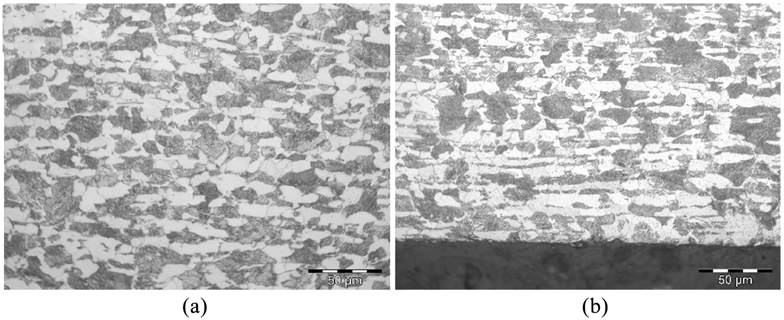
Microstructure of a longitudinal cut from the steel bar before turning: (a) region 1 mm away from the surface and (b) original sample surface.
Micrographs of two samples were combined to compare their surface finishing quality (Figure 12)). Samples 03 (regular) and 09 (irregular) were turned with similar feed and nose radius. However, the variation in other turning parameters (rake angle and cutting speed) was responsible for producing distinct finished conditions and residual stresses.
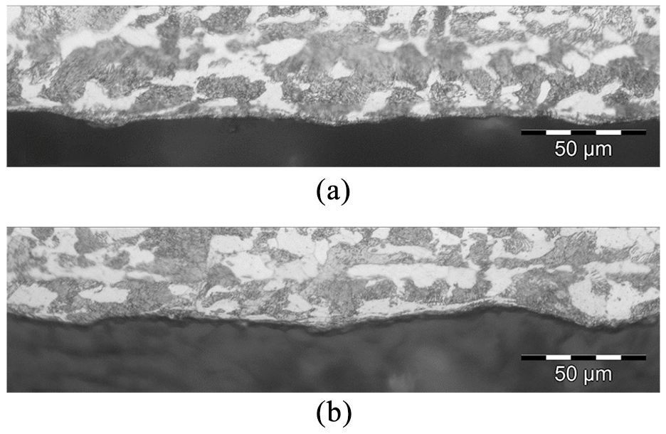
Microstructure of the turned surface: (a) sample 03 showing a regular surface finishing and (b) sample 09 presenting an irregular surface finishing.
Despite similarities in mean roughness and cutting depth, sample 09 presented higher amplitude of roughness peaks and valleys than sample 03. Also, sample 03 showed a more homogeneous roughness at the surface. Besides, sample 09 (irregular surface finishing) showed a heterogeneous pattern and more elongated grains at the surface. The irregular surface finishing of sample 09 suggests excessive deformation during turning (surfaces became irregular due to more deformation and reduced shear during machining). This deformation phenomenon favors mechanical residual stress mechanisms that promoted compressive residual stresses below the surface. Finally, sample 09 (irregular surface finishing) displayed lower surface tensile residual stress and higher compressive stresses below the surface up to 75 µm depth.
Conclusion
This study aimed at evaluating influences on residual stresses generated in AISI 1045 steel bars by turning with different parameters. Therefore, the findings of the current work can be briefly described as follows:
The greatest influences on residual stresses were promoted by feed rate and cutting velocity. In this sense, the feed rate was able to affect the residual stresses in both cutting and feed directions, while the cutting velocity only its own direction.
Tool nose radius in the studied range only slightly affected the surface residual stress and did not considerably change residual stresses at deeper layers.
Tool rake angle affected residual stresses not significantly for the investigated conditions (−6° to 7°).
Turning with a combination of high cutting speeds and feed rates should be avoided, as this has the main impact for heat generation at the surface, leading to high surface tensile residual stresses, as it was found with one combination set (250 m/min, 0.25 mm/rev) opposing the results obtained with lower cutting and feed rate values (150 m/min and 0.10 mm/rev, respectively).
Obtaining good surface finishing is normally accomplished by increasing cutting velocities, decreasing feed rates and with negative tool geometry. But, increasing velocities too much will increase the heat generation and contribute for the tensile residual stresses, therefore samples that exhibit regular surface finishing can present high surface tensile residual stresses. On the other hand, compressive residual stresses were found for samples with irregular surface finishing, showing that there is no obvious combination of parameters to increase residual stresses and surface finishing quality at the same time, and a compromise must be done. Samples with regular and irregular surface finishing showed remarkable differences concerning the residual stress states. Thus, a stable and regular cutting with suitable turning parameters plays an important role to decrease the tensile residual stresses.
Footnotes
Acknowledgements
The authors would like to thank CNPq (National Council for Scientific and Technological Development) and CAPES (Brazil) for their support. In addition, we acknowledge Laboratório de Manufatura Mecânica (LAMAM)-SATC for turning. Finally, we also thank Laboratório de Metalurgia Física (LAMEF/UFRGS) for residual stress measurements.
Declaration of conflicting interests
The author(s) declared no potential conflicts of interest with respect to the research, authorship, and/or publication of this article.
Funding
The author(s) received no financial support for the research, authorship, and/or publication of this article.