
Abstract
The goal of this experimental study is to manufacture a bolted GFRP flange connection for composite pipes with high strength and performance. A mould was designed and manufactured, which ensures the quality of the composite materials and controls its surface grade. Based on the ASME Boiler and Pressure Vessel Code, Section X, this GFRP flange was fabricated using biaxial glass fibre braid and polyester resin in a vacuum infusion process. In addition, many experiments were carried out using another mould made of glass to solve process-related issues. Moreover, an investigation was conducted to compare the drilling of the GFRP flange using two types of tools; an Erbauer diamond tile drill bit and a Brad & Spur K10 drill. Six GFRP flanges were manufactured to reach the final product with acceptable quality and performance. The flange was adhesively bonded to a composite pipe after chamfering the end of the pipe. Another type of commercially-available composite flange was used to close the other end of the pipe. Finally, blind flanges were used to close both ends, making the pressure vessel that will be tested under the range of the bolt load and internal pressure.
Keywords
Introduction
Bolted flange joints made of fibre reinforced plastic (FRP) are widely used in many industries such as oil, gas chemical, petrochemical, power plants and offshore. This is because the systems in these industries usually include pumps, valves and other fittings that require periodic removal for maintenance. Fibre reinforced composites are an attractive option due to their unique combination of high strength and modulus to weight ratios and high corrosion resistance.1,2 For instance, the weight of a 12-inch diametre pressurised fuel line for carrying liquid hydrogen in a space shuttle was reduced by 20% when it was manufactured from composite materials. 3 Furthermore, FRP materials have a long life expectancy and low installation and maintenance costs. 4 Another important advantage of FRP is that designers have the ability to vary the material properties for a specific application. For example, high resin content provides maximum corrosion resistance; high glass content provides maximum physical strength. Therefore, designers can combine these two elements to produce a reliable design. Similarly, designers can also vary the mechanical properties by changing laminate design to resist a specific load in a specific direction. Moreover, the use of composite flanges to connect composite pipe helps to avoid the mismatches during differential thermal expansions of metal connecting pieces and composite pipes. 5
In terms of the literature review, only a very few studies have focused on the manufacturing of the composite flange joints. Tao et al. 5 compared the connection between composite poles and composite flanges instead of aviation-grade aluminium alloy flanges in a stratosphere truss structure. They used a Toray T700S–12K carbon fibre in three-dimensional full five directional braiding technology and tri-functional epoxy resin TDE – 85# through RTM (resin transfer moulding) process to manufacture the flange. The results show that the joint of carbon fibre poles with the carbon fibre reinforced polymer bolted flange performed better than the metal flange under the same operating conditions. Whitfield et al. 6 conducted an experimental and numerical investigation for creep and unsymmetrical shrinkage during the post-cure of GFRP flange. The flange was fabricated by using hand lay-up with a steel mould. The raw materials used were chopped strand mat fibre and Derakane Momentum 411-350 Vinylester resin. Many strain gauges were embedded between the layers and on the outer surfaces. They observed that the correlations between spring back results are poor but for strain, results are good. The authors mentioned two possible reasons, firstly, various cure profiles were applied at various stages of the lamination process and secondly, the thermal stress related creep in the resin at the elevated temperature during post-cure.
Kurz and Roos 7 carried out experimental, numerical and analytical investigations on the design of floating type bolted flange connections (loose flange) made of GFRP materials capable of working at temperatures up to 80°C in chemical industries. They used various types of gaskets made of rubber (EPDM) and polytetrafluoroethylene (PTFE) to check the gaskets’ performances with a GFRP bolted flange at the elevated temperature. It is found that both the PTFE-gasket and PTFE-gasket with diffusion barrier perform better than EPDM-gaskets. The bolt-force decreased with heating up to 80°C and bending occurred at the top surface of the flange. The results of analytical, experimental and FEA simulations all have shown good agreements with each other. Fangueiro et al. 8 conducted experimental investigations on the development of FRP T-pipe joint. 3D weft-knitted fleecy fabrics with different structures such as fleece yarn linear, average ground yarn and average fleece yarn were tested to improve the mechanical properties. Glass fibre, polyester resin and the RTM process were used with to fabricate the connection. The results show that the sample PA Glass 544 Tex exhibited the best performance to manufacture the T-connection with 43% fibre mass fraction and this is close to the desired value of 40%.
In the present work, an experimental investigation was conducted to manufacture a glass fibre reinforced plastic (GFRP) bolted flange by using glass fibre braid, polyester resin and a vacuum infusion process. This particular type of fabric was chosen because of its continuity over the entire flange body. Therefore, it is anticipated that the failure that usually occurs at the flange-hub intersections due to the discontinuity of fibres in this region will be minimised. In addition, a number of experiments were conducted to improve the method of flange fabrication thus to obtain a composite flange with high quality and performance.
Designing the mould
Designing the mould is one of the important factors that has significant effects on the manufacturing of composite flange using vacuum infusion. It not only determines the inherent quality of the composite material, but also controls the surface finish of the composite. Furthermore, the mould plays a significant role in maximising the properties of the composite material that are greatly affected by fabricating process. In this study, the mould was designed and manufactured with two parts to facilitate the flange removal from the mould after curing. These parts are the mandrel and the plate, as well as the O-ring gasket and the bolts.
Mandrel
The mandrel was made of 7″ diametre aluminium rod with. Aluminium alloy (6082 T6) was chosen due to its sufficient strength and dimensional stability to withstand the bag pressure loads and compressive load during the forming and curing cycles. To achieve the required dimensions, the rod is machined and tapered from one edge as shown in Figure 1. The purpose of this taper, which is equal to 1.75°, is to achieve the requirements of the taper-taper joint between the flange and the pipe and also to facilitate the removal of the flange from the mould and to avoid the stacking problem or damage to the flange. The external surface of the mandrel that is in contact with composite is subjected to surface finishing process to remove all asperities that increase the chance of the flange mould stacking and also to obtain a flange with good internal surface. This will improve the bonding strength between the flange and the pipe. In addition, the tapered end face of the mandrel was machined to create a groove for the O-ring rubber gasket (3.53 mm of cross-sectional diametre) and four holes with threads were created for inserting the bolts during assembly.
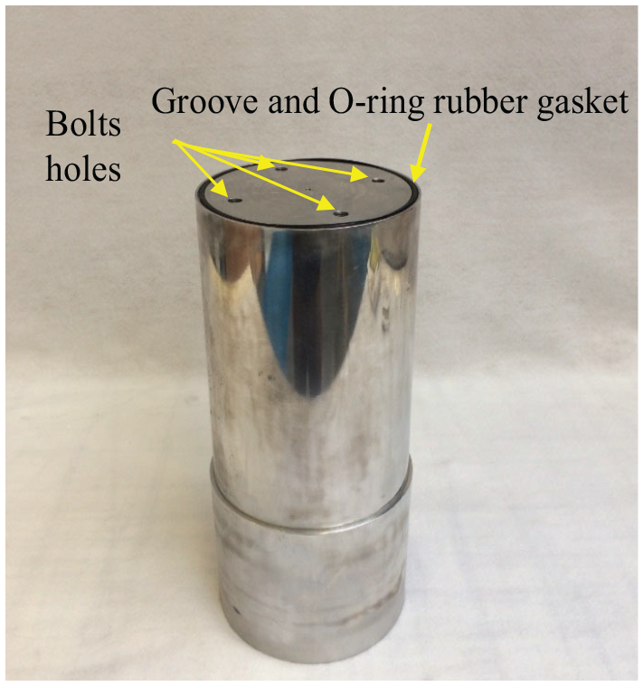
The mandrel.
Plate
The second main part of the mould is the plate, which is placed at the bottom and in direct contact with the lower flange face. Therefore, it requires a good surface finish to avoid sticking over this area. Initially, the plate was made of aluminium alloy (6082 T6) with dimensions 650 mm × 650 mm × 10 mm and four holes were drilled around the centre of the plate for the assembly purposes. During the infusion process, the resin flow was found to be problematic and this will be discussed in detail later. This led to the replacement of the aluminium plate by one that was made of glass. See Figure 2. The reason of choosing glass material is to observe the resin flow during the infusion process and find the best input and output positions for the resin.
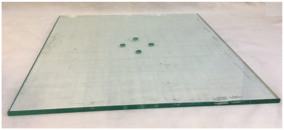
The glass plate.
The mould assembly
As showing in the Figure 3, the parts of the mould were assembled by using four bolts of size M10 as well as an O-ring rubber gasket. These bolts pass through the plate holes and are fastened to the identical holes that were drilled in the taper end face of the mandrel by using a thread tool. Before the assembly, the gasket was fitted in the groove. The purpose of using this gasket is to prohibit the leakage through holes of the bolts during the vacuum and to prevent the resin from reaching the contact area between the mandrel and the plate during the infusion.
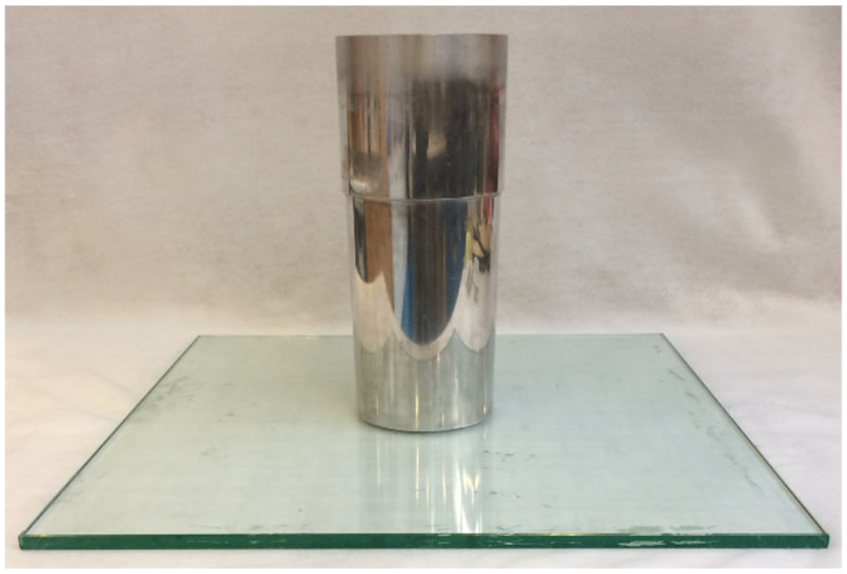
The mould of the composite flange.
GRP flange fabrication
The geometry of the flange and the dimensions were chosen based on the ASME boiler and pressure vessel code, Section X 9 when the internal pressure is 3.4 bar. The vacuum infusion process (bag moulding) was chosen to manufacture the composite flange of 6-inch nominal diametre. This manufacturing method was selected due to its flexibility for manufacturing composite with complex geometry. It is cheap and it provides good strength compare with other methods such as hand layup or RTM, which also require a closed mould. Figure 4 illustrates a schematic of manufacturing GFRP flange by using a vacuum infusion process. This manufacturing process has included a number of steps which are described briefly as follows:
1.
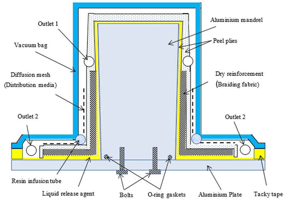
Schematic diagram of the vacuum infusion process.
For the second instance, it is used between the fabric and the diffusion mesh as well as the bag to prevent them from sticking to the composite flange after the curing action and to improve the outer surface finish of the flange.
2.
3.
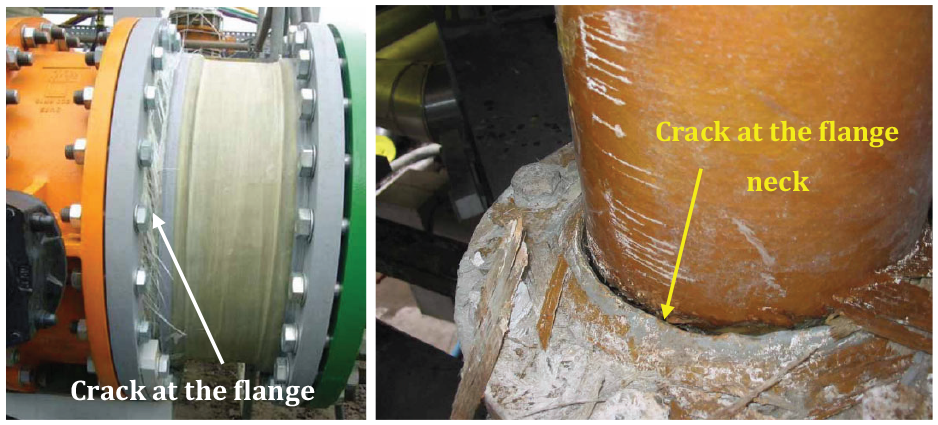
Common failure on the GFRP flanges. 10
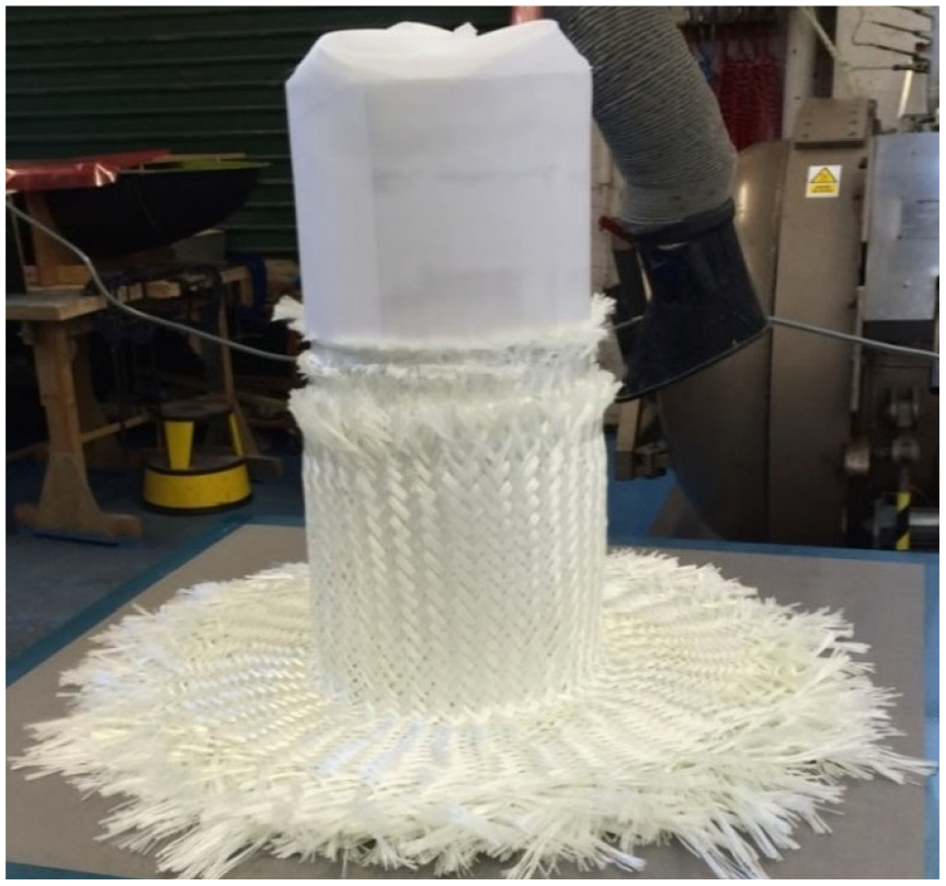
Laid braided fibreglass fabric on the mandrel and the plate.
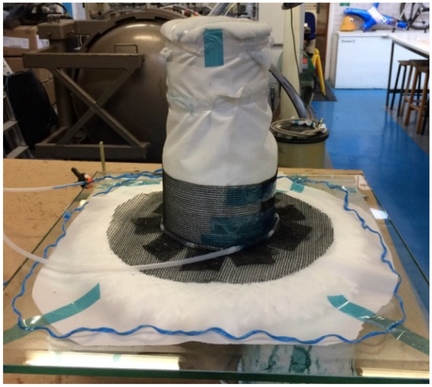
Diffusion mesh distribution.
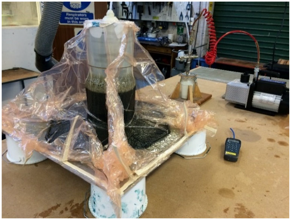
Bagging and resin infusion process.
The vacuum is applied until the flange is completely cured at the room temperature. After the curing, the vacuum is released, vacuum bag, diffusion mesh and peel ply all are stripped off and the flange is removed from the mould.
4.
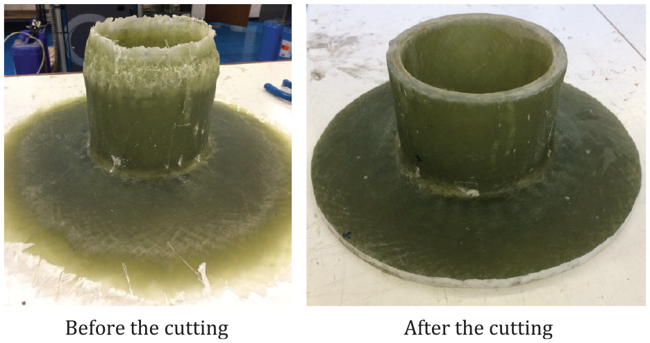
Machining of the composite flange.
Issues with the manufacturing process
During the manufacturing of the GFRP flange, two issues were identified: (1) inadequate resin flow and (2) voids and cracks at the flange neck. Details of these issues are discussed below.
Resin flow problem
The main issue that was faced during the GFRP flange fabrication process is the inadequate resin flow. This has led to have dry regions around the diametre of the bolts holes circle and at the lower face as illustrated in Figure 10. Initially, the inlet of the resin was placed at the outer diametre or edge of the flange disc while the outlet was fixed on the top. The first flow flows through the diffusion mesh at the top surface of the flange from the resin inlet, which was allocated at the flange edge, towards the centre. Some of this resin passed through the thickness (fabric) at the flange-hub intersection due to the sudden changing in the geometry and started to flow in the opposite direction (reverse flow) towards the outer diametre at the bottom face of the flange. The second flow travels from the inlet towards the centre at the bottom face of the flange. At some points, these flows met and trapped air at the meeting regions. Thus, the resin doesn’t fill the meeting regions properly and leads to dry regions, which are illustrated in the Figure 10.
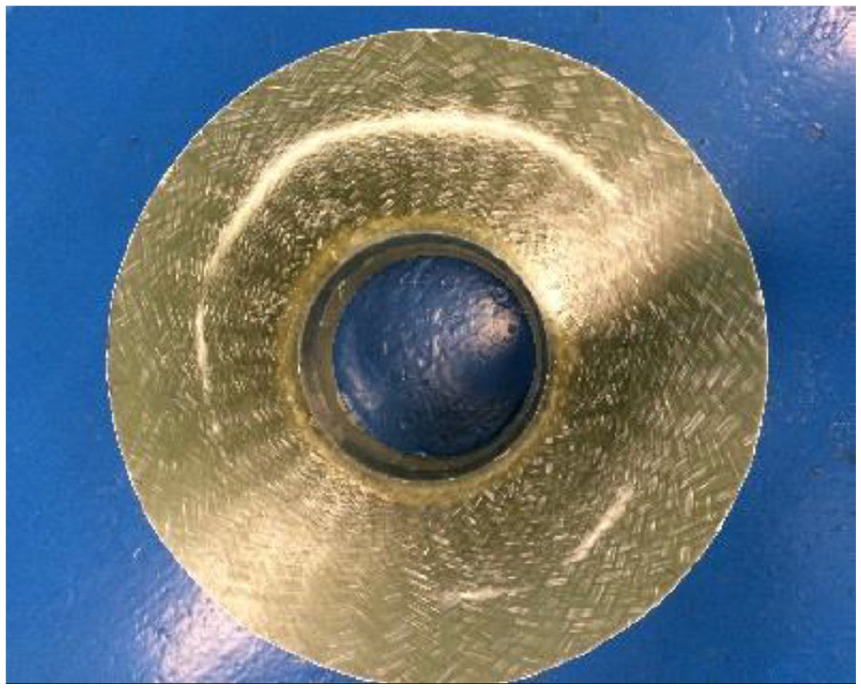
Flange with dry regions on the face.
Voids and cracks problem
After curing the composite flange, it was cut into many pieces for mechanical tests, measuring the fibre volume fracture (Vf) and capturing optical microscopy images. In order to investigate the voids and the cracks, many samples were taken from the flange-hub region (flange neck), which represents the critical point in the flange. Figure 11 shows an image of the flange neck region. It can be seen that many voids and cracks occur at this region when the inlet of the infusion was in the flange edge and the outlet was in the top of the flange. This case is named as Model A, which will be discussed later. In addition, most of the voids and cracks were found close to the upper face of the flange. This occurs due to the resin shrinkage and exothermal behaviours at the flange neck. As this region connects the flange and the hub, it experiences the most effects of the flange shrinkage. Also, it is the thickest part in the flange, thus high temperature is produced due to exothermal reaction.
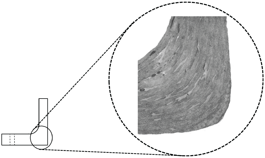
Microscopy image for the flange-hub intersection.
The reason of the voids and the cracks concentrate at the upper half of the flange is that the lower surface and the internal faces of the flange are bigger than the upper face and they have direct contacts with the mould, which is made of aluminium and glass. The mould helps to cool the composite by transferring the heat through it to the environment. In contrast, the upper face of the flange-hub intersection area is less and covered by the peel ply and the vacuum bag, which are inhibiting the heat transfer. Therefore, the amount of the transferred heat from the lower and the internal faces of the flange is more than that from the upper face. As a result, most of the voids and the cracks were formed at the upper half of the composite instead of the lower half. These voids and cracks represent weak points in the flange body and the stresses concentrate around them. In addition, they occurred at a critical region of the flange, which is the flange neck. Most of the failures in the current commercial composite flanges occur at this region. This region is usually subjected to high bending moment due the applied bolt load and internal pressure. Therefore, the voids and crack should be minimised as much as possible to avoid any possible failure in this area.
Solving the issues
To solve or minimise the issues faced during manufacturing the GFRP flange, two investigations were carried out. The first investigation, which involves a substantial number of experiments studies the effect of the inlet and the outlet positions of the resin on the formation of the dry areas, voids and cracks. The other investigation is conducted by changing the infusion temperature to study its influence on the viscosity of the resin.
Resin inlet and outlet positions effect on the resin flow
Changing the inlet and the outlet positions of the resin in the vacuum infusion process is one of the important parameters that has significant effect on the flange strength and especially on the issues of concern, that is, dry region, voids and cracks. To investigate this, another mould was manufactured from glass as shown in the Figure 12. This allows the resin flow through the mould at any region during the infusion process to be visible. In addition, in each experiment, a portion of the flange was fabricated using the same fabric, resin and manufacturing process as illustrated in Figure 13.
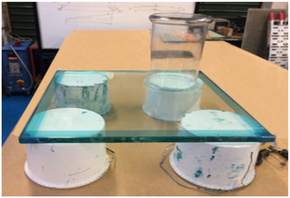
Glass mould of the experiments.
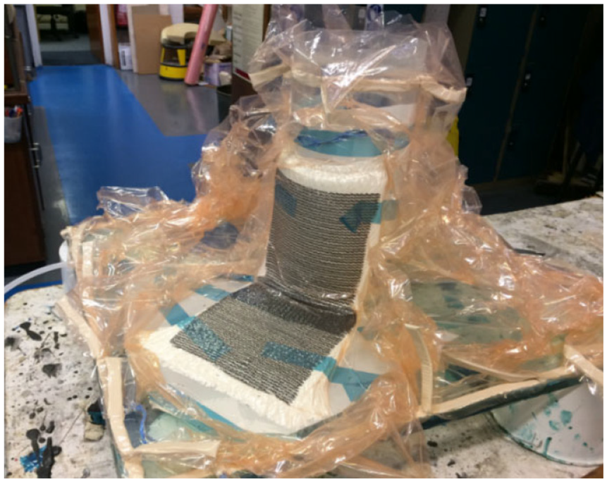
The vacuum infusion process of the experiments.
Three experiments with different inlet and outlet positions of the resin were carried out. These experiments were called Model A, Model B and Model C as shown in Figure 14. Model A has the inlet at the outer diametre of the flange (flange edge) and the outlet in the top of the flange. Model B has the inlet at the top of the flange and the outlet at the flange disc edge. The third one is model C that includes the inlet at the flange neck and two outlets-one at the flange disc edge and the other at the top of the flange hub. During the infusion, the resin flow was video-recorded. The results showed that the model C has achieved the best resin flow and also quicker than the other models. This helps to distribute the resin over all the flange body within a short time and avoid any dry fabric which occurred with the model A (See Figure 15).
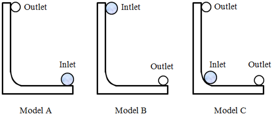
Inlet and outlet positions of the conducted experiments.
Flange without dry fabric on the face.
In addition, a sample was taken from the flange neck (flange-hub intersection) for each experiment to study the voids and the cracks under the microscope. Then, the voids and the cracks percentages were also calculated by using Image J software for each sample. The optical microscope images of the samples and the percentage of the voids and cracks are shown in Figure 16. The results showed that the voids and the crack percentages reduced significantly in the Model C (4.3% for Model A, 4.24% for Model B and 1.58% for Model C). This was taken into account to choose Model C for manufacturing the final form of the composite flange.
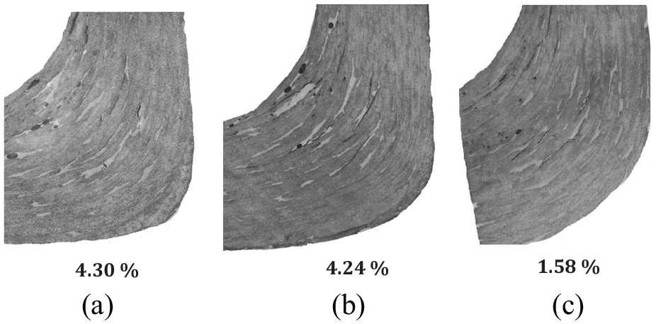
Microscope images at the flange-hub intersection: (a) model A, (b) model B, and (c) model C.
Furthermore, the temperatures at the flange–hub intersection and through the thickness were monitored for the Model C during the infusion and throughout the curing. This is done by embedding a thermocouple through the composite layers at the aforementioned position, which is illustrated in the Figure 17. This region was chosen because it is the thickest and expected hottest part in the flange body due to small surface area, which limits the heat transfer.
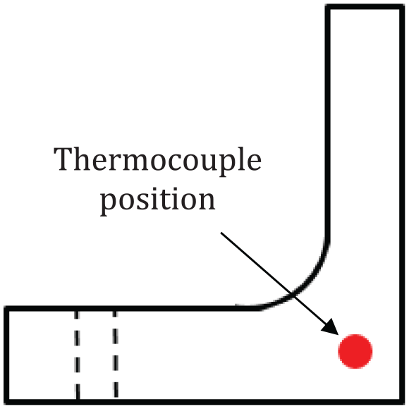
Thermocouple position in the flange-hub intersection.
The variation of the temperature with time was shown in Figure 18. The results showed that the temperature has increased during the first 3 h but decreased later. The room temperature was 18.3°C. The maximum temperature was 31.2°C after 3 h from the starting time. This is because of the exothermal reaction during the infusion and curing of the resin. However, the variation range was not high enough in this model (C) and that was because of the position of the inlet resin infusion. This helps to cool this part by transferring the heat from this part to the others through the resin, which flow through this region. This in turn helped to reduce the voids and cracks in this part for the model C.
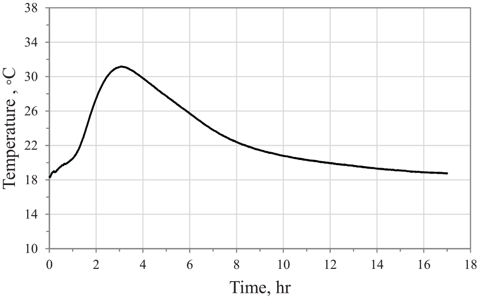
The temperature variation during the infusion and curing process at the flange-hub intersection.
Resin viscosity effect on the void content and dry regions
The viscosity of the resin has also significant impact on the resin flow and on the curing time. The resin viscosity can be changed by varying the temperature. Therefore, experiments were conducted to find out the best infusion temperature that reduces the viscosity and facilitates the flow of the resin through the layers of the fabric. The experiments were carried out using the Brookfield rheometer machine with flat disc and at constant rotation speed for range of temperature (20–50°C). The viscosity has been measured for the polyester resin with zero% and 1% catalysts. The resin without catalyst was tested to see the effect of the evaporation on the resin viscosity. The 1% catalyst was chosen because the manufacturer has recommended the ideal range of the catalyst as 1%–2%. Therefore, it was fixed to 1% to increase the curing time thereby ensuring good distribution of the resin.
Figure 19 explains the viscosity variation of the resin with the time for various ranges of temperature. The results show that the viscosity increases from 0.25 Pas to almost 2.2 Pas during the first 30 min of the time regardless the temperature. After that, the recorded viscosity has decreased. In reality, it should not decrease but it happened because the resin film separated into two layers. One of them has sticked onto the upper plate and the other sticked onto the lower plate of the device. The recorded viscosity after the peak is affected by the friction between the two layers. The temperature has an insignificant effect on the viscosity when the resin is used without catalyst.
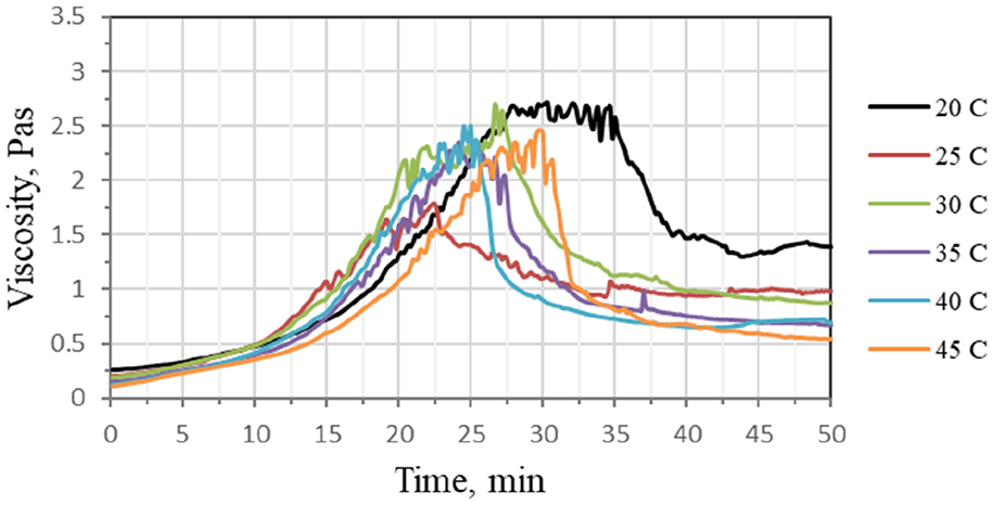
The variation of the polyester viscosity with the time at different temperature (without catalyst).
Figure 20 illustrates the variation of the resin viscosity with time for different temperatures (20–50°C) for the resin mixed with 1% of the catalyst. It seems that the temperature has significant effect on the resin viscosity. At the high temperatures, 35–50°C, the resin viscosity increases rapidly and the resin is cured quickly. In addition, the torque has reached the maximum allowable torque of the device and the break has occurred. The time of the break decreases with the increase in the temperature. At the temperatures 25 and 30°C, the viscosity has increased up to 2.5 Pas during the first 30 min but dropped after that. This means the resin film has split into two layers. At the room temperature (20°C), the viscosity has also increased up to 2.5 Pas during the first 35 min and reduced gradually after that. The longest period with less viscosity was achieved at the temperature 20°C. Therefore, this temperature was chosen to infuse the composite flange. This temperature allows the resin to distribute gradually over all regions of the fabric before curing. Furthermore, it lets the trapped air to move and leave the resin. Finally, at the room temperature, it does not require any heating system thus makes the manufacturing process efficient and reduces the costs.
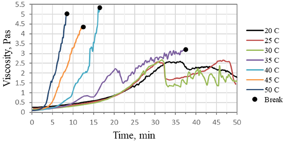
The variation of the polyester viscosity with the time at different temperature (1% catalyst).
Composite flange drilling
Drilling the composite flange is one of the main fabrication steps after the curing. The bolts’ holes are also critical regions in the GFRP flange due to the applied bolt force. So that, the holes’ performance has significant effect on the flange performance as most of the maximum stress and strains concentrate at the bolts holes. In addition, it was found that the composite flange with drilled bolts holes performed better, in terms of strength, than those with moulded holes. 12 A number of researchers11,13 have carried out comparative studies on the drilling of the glass fibre reinforced plastics (GFRP), which are manufactured by hand lay-up, using a Stub Length drill and a Brad & Spur K10 drill. They found that the Brad & Spur K10 drill produced less damage on the GFRP composite than the Stub Length.
In this study, a comparative study was conducted using two types of drilling tools with the same cutting conditions for a GFRP plate made of the same fabric and the resin which were used to manufacture the flange. These tools are Erbauer diamond tile drill bit and Brad & Spur K10 drill, which are illustrated in the Figure 21. The Brad & Spur K10 drill was recommended by Davim et al. 13 The results were evaluated in both sides (Inlet and Outlet). As shown in the Figure 22, the Erbauer diamond tile drill bit has produced a hole with less damage and better than the Brad & Spur K10 drill in the both sides, that is, the inlet and the outlet of the hole. Therefore, Erbauer diamond tile drill was chosen to drill the holes of the bolts for the composite flange used in this study.
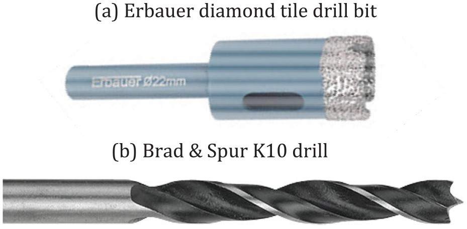
Drilling tools of the composite.
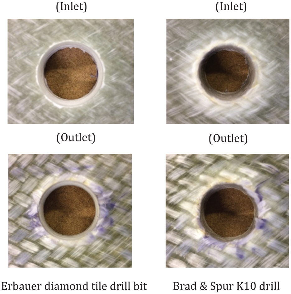
22 mm drilled holes of used tools in the experimental work.
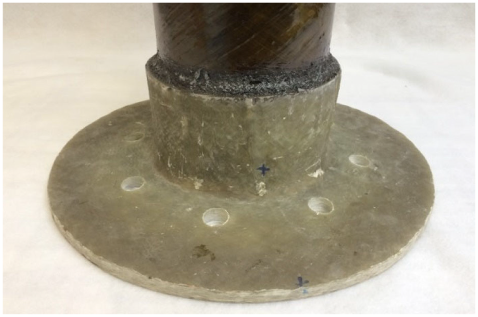
In addition, other experiments were conducted to find out the best rotation speed for the Erbauer diamond tile drill bit. The same feed rate for all cases and various speeds, for example, 600, 800, 1200 and 2200 rpm were used to drill the same composite laminate as shown in Figure 23. The findings show that the best hole in both sides was achieved at the rotation speed of 800 rpm. So that, these conditions have been chosen to drill the fabricated composite flange as illustrated in Figure 24. During drilling, water was used to reduce the heat and to avoid the burning of the composite around the holes.
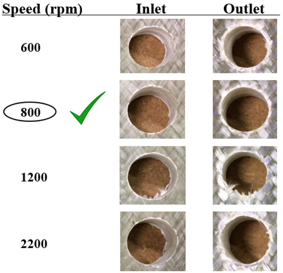
Drilled holes with different speeds.

During the drilled and the final GFRP flange.
Flange-pipe adhesive bonding
Flange-pipe bonding is important and it was done through many steps. Firstly, the filament winding pipe shown in Figure 25 was chamfered at its ends to achieve the requirements of the taper-taper joint between the flange and the pipe. The internal face of the flange was sanded to improve the bonding strength. Epoxy adhesive (PSX®-60), which is provided by a commercial company Pipex, was used. The adhesive bonding was reinforced by steel particles. Secondly, an axial force was applied using hand puller winch to combine the flange and the pipe. The purpose of using this tool is to apply axial force on the flange-pipe joint during the bonding process. This force increases the contact surface area between the flange, the pipe and the adhesive, subsequently maximises the strength of the adhesively bonded joint. A heating blanket was placed at the inside of the joint. The purpose of the electric heating blanket is to heat up the joint and keep the temperature constant at 130°C, (as recommended by the supplier) during the curing process. Figure 26 shows the flange-pipe joint after the bonding. The other end of the pipe was closed using a Heavy Duty flange, which was installed using the same procedure as the FRP flange. See Figure 27(b).

Chamfering the composite pipe.
Flange-pipe adhesive bonding.
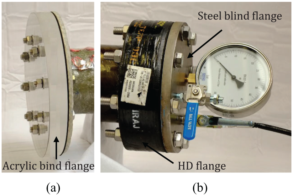
HD and blind flanges: (a) acrylic blind flange attached to the fabricated flange and (b) HD and steel blind flange attached to the HD flange.
Blind flanges
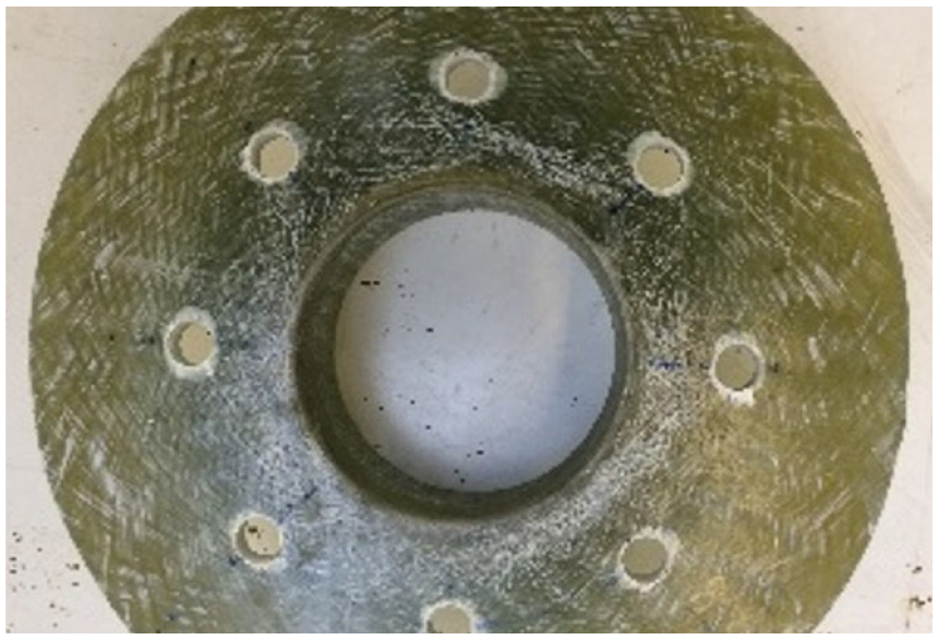
Two blind flanges were used to close the ends of the pipe, which were bonded with the fabricated flange in one end and the HD flange in other end of the pipe. The blind flange used for closing the fabricated flange was made of Acrylic material of thickness 50 mm as shown in Figure 27(a). The reason for choosing this type of the material is that it is strong and provides clear views for flow observations across the compressed gasket and the leakage propagation. Unfortunately, the leakage propagations have taken place between the gasket and the flange, which cannot be seen. However, the blind flange was made as thick as possible to avoid any deformation on the blind flange. Eight holes, which are identical with holes of the flanges were made to insert the bolts. Initially, water jet cutter (Flow Mach 2 203Ib) was used to make the holes but unfortunately, many cracks around the holes appeared. As a result, a CNC machine was used instead of the water jet cutter to make holes for the bolts.
The blind flange for the other end, which is bonded to the HD flange, was made of mild steel of thickness 25 mm. Eight holes were made for the bolts. In addition, three holes were drilled for the inlet, outlet and the pressure gauge. See Figure 27(b).
Assembly of the joint components
After manufacturing all the components of the pressure vessel, the final assembly was carried out as shown in Figure 28. Many strain gauges were bonded on the GFRP flange body to test the pressure vessel. The pressure vessel has been tested under range of the bolt load and internal pressure using different types of gasket, which are used for oil and gas applications. Some of the results of the project have been published in references14–19 and the rest will be published in the next articles.
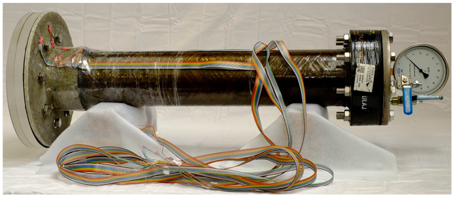
The pressure vessel.
Conclusion
A bolted composite flange made of glass fibre braid reinforced polymer provides good solutions to tackle the most common types of failures found in commercially-available GFRP flanges manufactured by hand lay-up or filament winding processes. In this paper, the bolted GFRP flanges were fabricated using a bespoke mould and vacuum infusion process (bag moulding). The flange is made of 2D glass fibre braid and polyester resin. In addition, a number of experiments were conducted using different glass mould to solve the issues faced during the fabricating process, to improve the manufacturing process and to obtain a GFRP flange with high quality and strength. Furthermore, to improve the quality of the drilled flange holes, a comparative study was carried out using two types of drill bits. Many different cutting conditions were applied to find the best. Several GFRP flanges were manufactured to improve the manufacturing process and obtain a bolted flange joint made of composite materials with high quality and performance.
Footnotes
Acknowledgements
This study was a part of my PhD project, which is titled the design and manufacture of a glass fibre reinforced polymer (GFRP) bolted flange joint for oil and gas applications. This project includes also a numerical study and testing the pressure vessel and the other results will be published in next articles. So that, the author would like to thank supervisors and all technicians, who contributed in the study, in Plymouth University. The authors also would like to gratefully acknowledge the financial supports provided by the HCED in Iraq and thank Pipex for providing some of the materials and technical support.
Declaration of conflicting interests
The author(s) declared no potential conflicts of interest with respect to the research, authorship, and/or publication of this article.
Funding
The author(s) received no financial support for the research, authorship, and/or publication of this article.