
Abstract
The deformation machining process (DMP) involves machining and incremental forming of thin structures. It can be applied for manufacturing products such as curved-surface blades without using 5-axis computerised numerical control machines. This work presents the effect of tool diameter and forming temperature on spring-back and dimensional accuracy of a simple fabricated part. The results of the first phase of the study are utilised to design the fabrication process of a curved surface blade. A feature-based algorithm is used to design the tool path for the forming process. The dimensional accuracy of the final product is improved through warm forming, two-point incremental forming, and extension of the bending zone to the outside of the product edges. The results show that DMP can be used to fabricate complex curved-surface workpieces with acceptable dimensional accuracy.
Introduction
The deformation machining process (DMP) has two steps: thin structural machining process and incremental forming process. The category of this process involves: ‘bending mode’ and ‘stretching mode’. In the bending mode, the raw material is first machined into the shape of a thin vertical wall. In machining, a relieved shank tool can have significant role for to diminish the friction between the tool shank and the machined surface. Next, the thin wall is bent incrementally using a hemispherical tool. In the stretching mode, the raw material is first machined into the shape of a thin floor and then deformed into a cup-like geometry by the forming tool. In this case, this process is very similar to the traditional incremental forming process. 1 Figure 1 depicts a schematic of the bending and stretching modes.
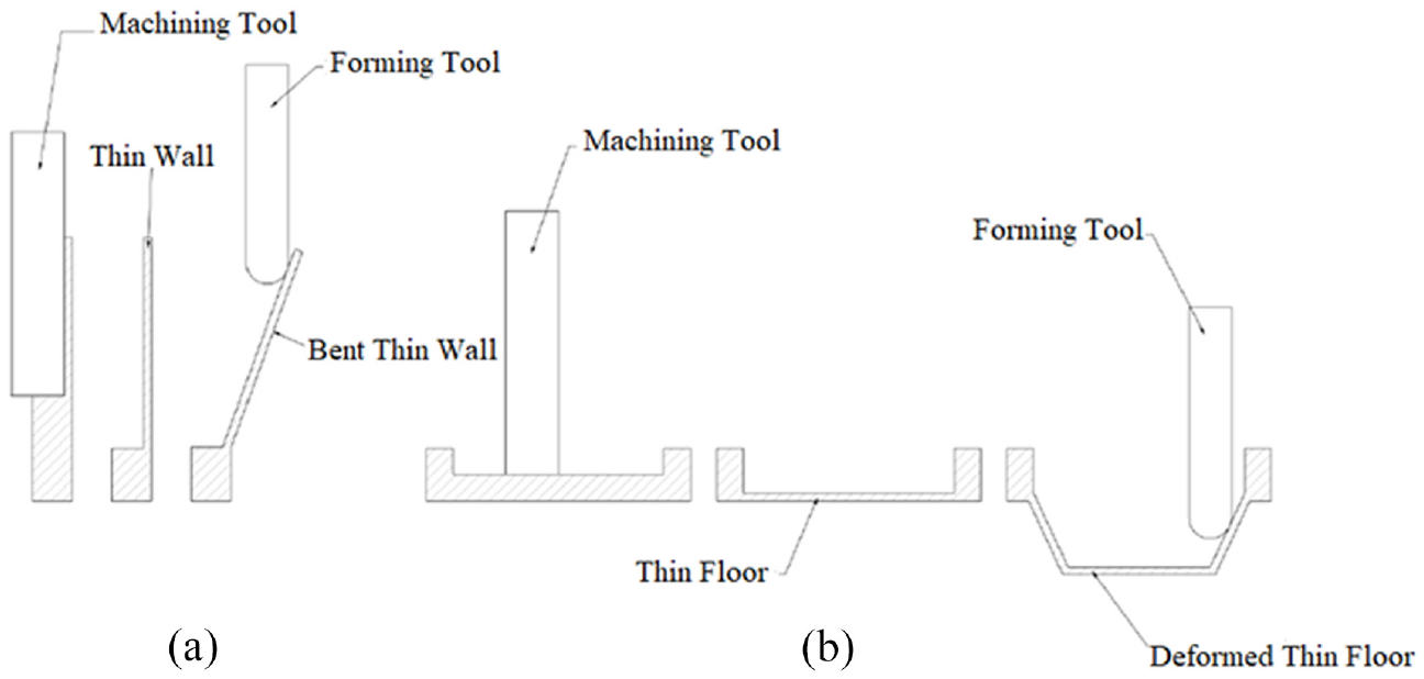
Hybrid forming machining: (a) bending mode and (b) stretching mode.
By using DMP, it is possible to create monolithic parts that have already been assembled. It is also possible to create parts using a 3-axis computerised numerical control (CNC) machine instead of using a 5-axis CNC machine, thereby saving material, which is another benefit of this method. Moreover, DMP can be used to manufacture products with special geometry, which are impossible to be produced with other manufacturing processes. 1
Thus far, only a few studies have been dedicated to DMP. Smith et al. 1 measured the forming forces during the process and found that the forming forces were less than the forces required to cut the raw material. Therefore, this process was preferred over other machining processes considering the advantages in terms of the force required. In another investigation, Smith et al. 2 studied the effect of process parameters on the quality of the final product in the bending mode. The material used in their research was AA 7050-T7451 aluminium alloy. They found that in the bending mode, the spring-back of the thin wall decreased with an increase in the final bend angle. They also stated that tool rotation during the forming process could cause unpredictable deformation on the wall. Agrawal et al. 3 compared DMP with single point incremental forming (SPIF) and conventional bending in terms of repeatability and fatigue life of the products. Their results indicated that conventional bending was the most repeatable process, and in contrast, SPIF was the least repeatable process. Moreover, with regard to the fatigue life, SPIF is preferred over the DMP. It was claimed that the residual stresses and changes in the grain structure of the material could be the reason for the machining process. Singh and Agrawal 4 studied the effects of the process parameters on the surface residual stress in the DMP. The parameters were classified into two categories: machining parameters (cutting speed, feed rate and cooling) and forming parameters (maximum bend angle and incremental bend angle). It was observed that compressive surface residual stresses were induced by the machining processes. Furthermore, with an increase in cutting speed, a decrease in residual stresses was observed due to the rise in temperature of the workpiece. It was also observed that by increasing the feed rate and using coolant, the residual stresses increase because of the increase in machining power and the decrease in temperature, respectively.
Asghar et al. 5 implemented an approach to reduce the deviation in the wall geometry. They mentioned that the axial and radial forces are two main parameters that play key role in sheet and base region geometrical deviation. The value of deflection was highly affected by tool path. By considering a compensated tool path, the dimensional accuracy in the wall was improved. Taherkhani et al. 6 considered tool step depth, tool diameter, feed rate and sheet thickness to simultaneously control the surface shape and dimensional accuracy. They showed that there is an adverse relation between surface roughness and tool diameter while there is a proportional relation between tool dimeter and dimensional error. Also, the larger step depth and feeding rate, the shorter forming time was achieved. Singh and Agrawal 7 evaluated factors affecting geometrical inaccuracies in the DMP. They concluded that the wall height to length ratio, bent angle and wall thickness were more important than the tool diameter, bending angle and bending feed rate in spring back. They found that the wall thickness and bending angle was affected by inclination at free end of bent structure.
According to previous studies, all the geometries fabricated by the deformation machining-bending mode were simple geometries with straight walls. However, practical industrial products have a much more complex geometry. The purpose of this study is to extend the capabilities of DMP to fabricate complex parts by fabricating a curved surface blade made of AA5083-O alloy. To understand the process, a thin wall was first bent using the same material, and the effect of process parameters such as tool diameter and forming temperature was studied. The results were then used to design the fabrication process for the curved surface blade. The initial tests on this workpiece resulted in a relatively large spring-back after forming, which is a serious issue. Therefore, to increase the dimensional accuracy, a two-point incremental forming was used to form the blade. To further reduce the amount of spring-back, the warm forming method was used in the forming stage. Using these two strategies, the dimensional accuracy of the final product could be considerably improved.
Materials and methods
Material properties
In this research, an AA5083 aluminium alloy has been used. To obtain the properties of the plate, a tensile test was performed according to the ASTM-A370 standard. The actual stress–strain curve obtained at room temperature is depicted in Figure 2.
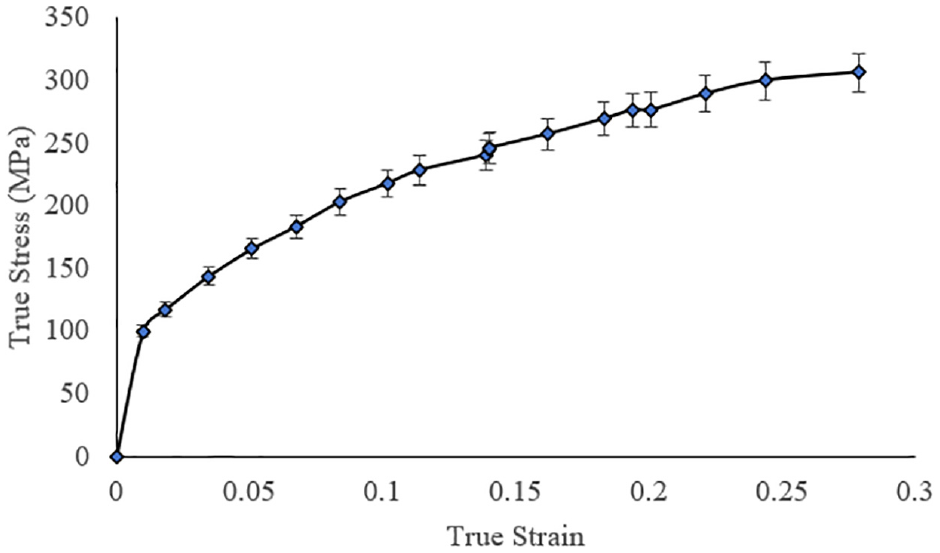
True stress–strain curve of the plate.
Blade forming process
Figures 3 and 4 show the forming process equipment and the dimensions of the planar and twisted blades, respectively. Blocks of the dimensions of 100 (width) × 130 (height) × 5.5 (thickness) mm3 and 50 (width) × 110 (height) × 5.5 (thickness) mm3 for planar and twisted blades were cut using a 3-axis CNC milling machine to create the geometry before forming. Initial blocks were machined to create a 1-mm-thick wall, as shown in Figure 4(a) and (b). A thermal element was placed near the root of the wall using a fixture and used to heat the samples. The temperature of the root of the wall was measured using an infrared laser thermometer. It was checked if the steady state was reached and maintained at the target temperatures, 50°C, 100°C, 150°C and 200°C, during the forming process. The root temperature was measured because it was expected that most of the plastic deformation occurred in the vicinity of the root. A thermocouple was also used to check and maintain the workpiece temperature during the forming process. Silicon-based high-temperature grease was used as a lubricant. The tool moved until it touched the wall and then zigzagged to incrementally bend the workpiece. Finally, the tool left the workpiece and allowed it to spring-back without any constraints.
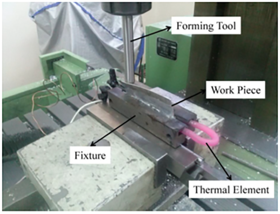
The forming process equipment.
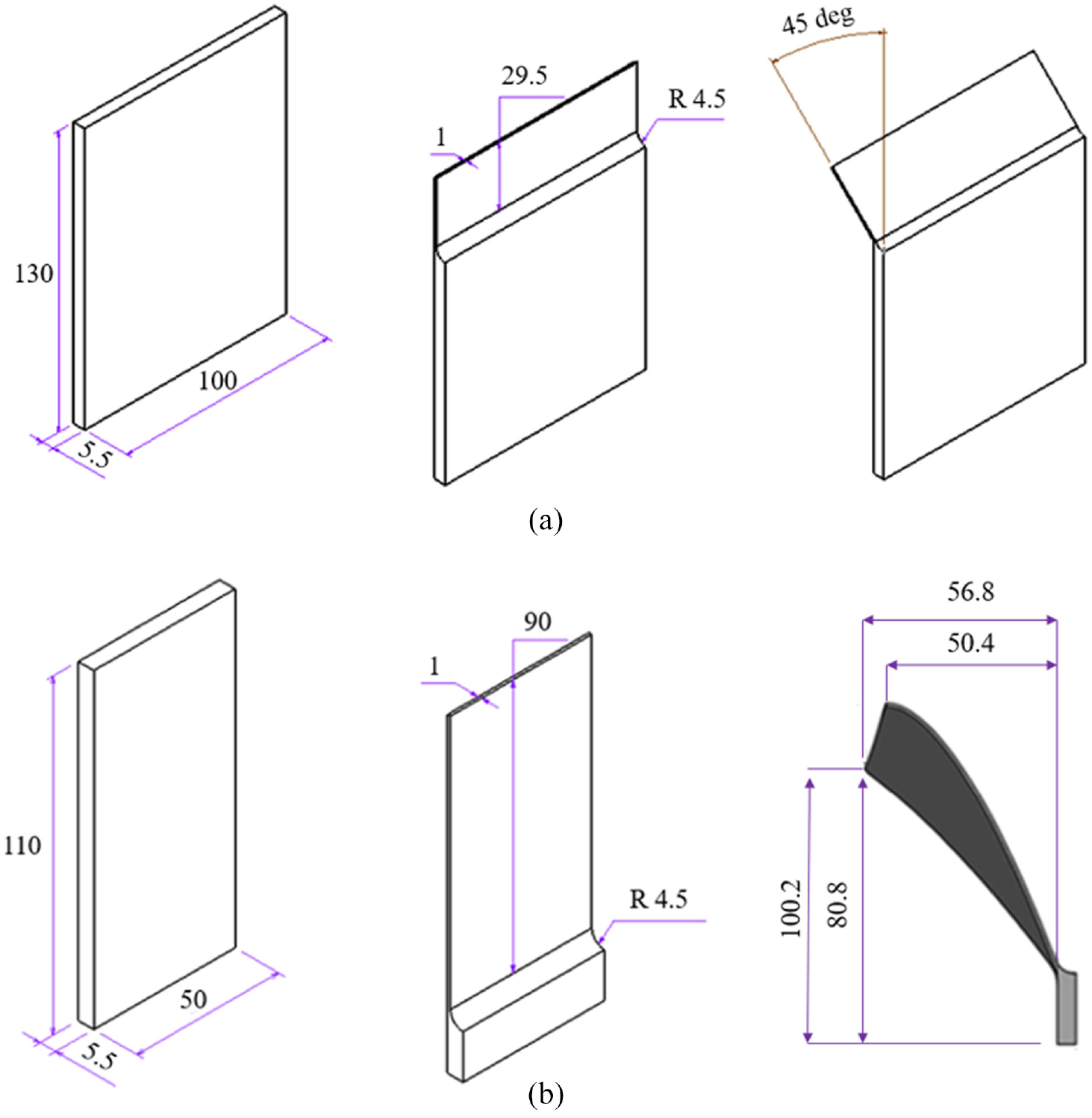
Dimensions of: (a) the planar blade and (b) the twisted blade (unit: mm).
The forming tool path and side view of the tool movement are shown in Figure 5. This tool path is similar to that used in Smith et al. 1
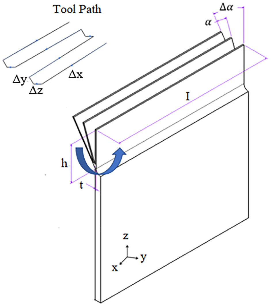
Tool path for deformation machining of the part shown in Figure 4(a).
Test conditions
In this work, the effects of the forming-stage parameters were studied. In general, the forming parameters of an incremental forming process include the tool diameter, forming temperature, forming tool feed rate, forming tool path pitch (i.e. distance between two identical points of two consecutive increments of tool path), and forming tool rotational speed.8–12 In the preliminary tests, it was observed that the tool feed rate and tool path pitch had a negligible influence on the amount of spring-back. In addition, as mentioned in Smith et al., 2 tool rotation causes unwanted deformation of the thin wall, and therefore decreases the dimensional accuracy. Therefore, the other significant parameters for the thin wall were the forming temperature and tool diameter. The selected levels for tool diameter and forming temperature were 10, 14 and 18 mm and 25°C (room temperature), 50°C, 100°C, 150°C and 200°C, respectively. The temperatures were chosen such that they were always below the recrystallisation temperature of the 5083-aluminium alloy.13–15 The tool diameter levels were selected according to the tool holder limitations, and a full factorial experimental design was considered. The experimental output is the change in the wall angle during the spring-back (%) according to equation (1):

where S is the percentage of change in the wall angle,
The final product is shown in Figure 6. During the forming process, the tool was allowed to rotate freely.
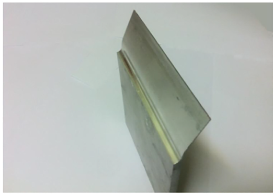
Planar blade fabricated by DMP.
Finite element analysis
For simulation, a 3D model of the hybrid forming analysis was conducted utilising the commercial finite element programme Abaqus/Explicit. The blade was considered an isotropic elastic-plastic and homogeneous material. To mesh the workpiece, we used 8-node linear solid elements in the reduced integration mode, that is, C3D8R. To prevent hour-glassing, the thickness of the thin wall was meshed using four elements. The tool diameters were 10, 14 and 18 mm, and the simulations were performed at room temperature. The tool was considered as a rigid body. The residual stress and friction coefficient within the tool and plate were ignored because the rotary movements were quite insignificant with regard to the process. Figure 7 illustrates the mesh parts of the tool and blade.
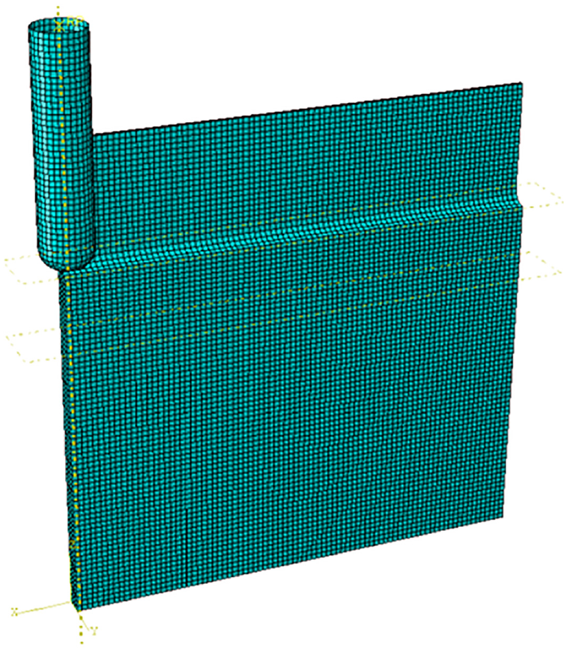
Mesh parts of the hybrid forming-machining process.
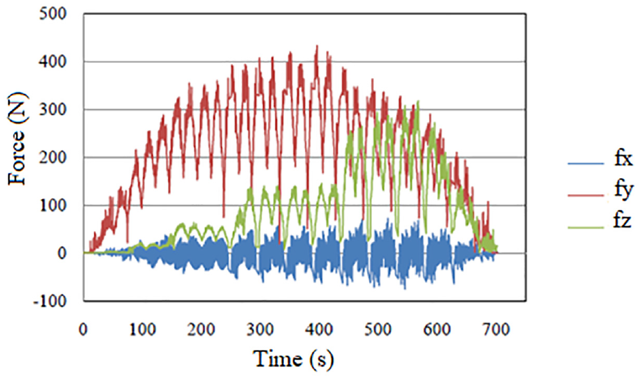
The forming forces of the tool, which had a diameter of 14 mm, were measured at room temperature using a Kistler 9255 B dynamometer to verify the simulated results. The experimental and predicted forces are shown in Figures 8 and 9, respectively. The experimental and predicted forces exhibit the same trend and order of magnitude. The discrepancy between the simulation and experiment may be attributed to the ignoring of several factors, such as the machining residual stresses and tool elastic deformation.
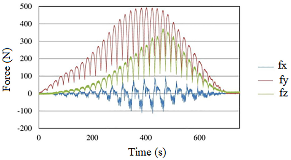
Measured experimental force versus forming time.
Predicted forces versus forming time.
Results and discussion
Planar blade
Stress concentration
FE simulations were used to find out the stress concentration at the root of the blade which may cause the initiation of cracks. Figure 10 depicts the von Mises stress distribution within the workpiece after the forming stage. It was observed that the stress was higher at the root where the plastic strain was higher than the rest of the workpiece. The stress reaches its maximum at both ends of the root, where the material is constrained only on one side. The material located in the middle of the root is constrained by the adjacent material points and changes the plastic deformation mode to plane strain bending. Therefore, the plastic strain is expected to be smaller in the middle than at the edges. The experiments also showed that during a few instances, the workpiece cracked at the root ends during the forming stage. The solution is to use a larger fillet in the root region to reduce stress concentration to prevent the initiation of cracks.
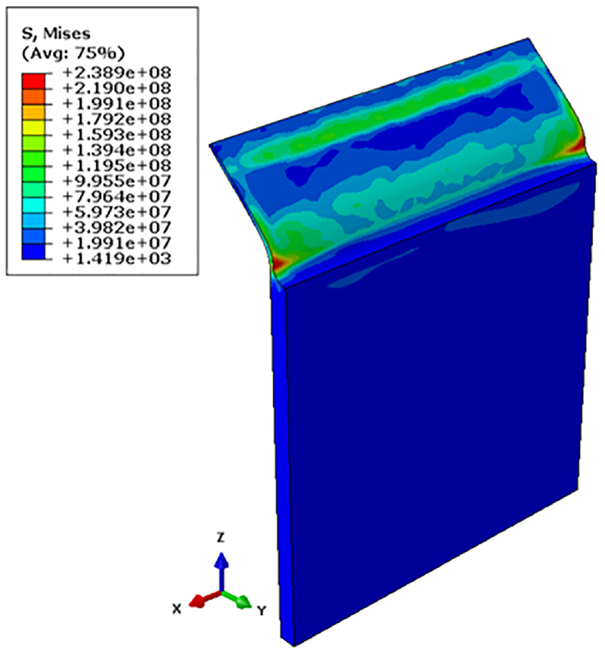
Von Mises stress distribution in straight wall bending after the forming stage (unit: Pa).
Effect of tool diameter on spring-back
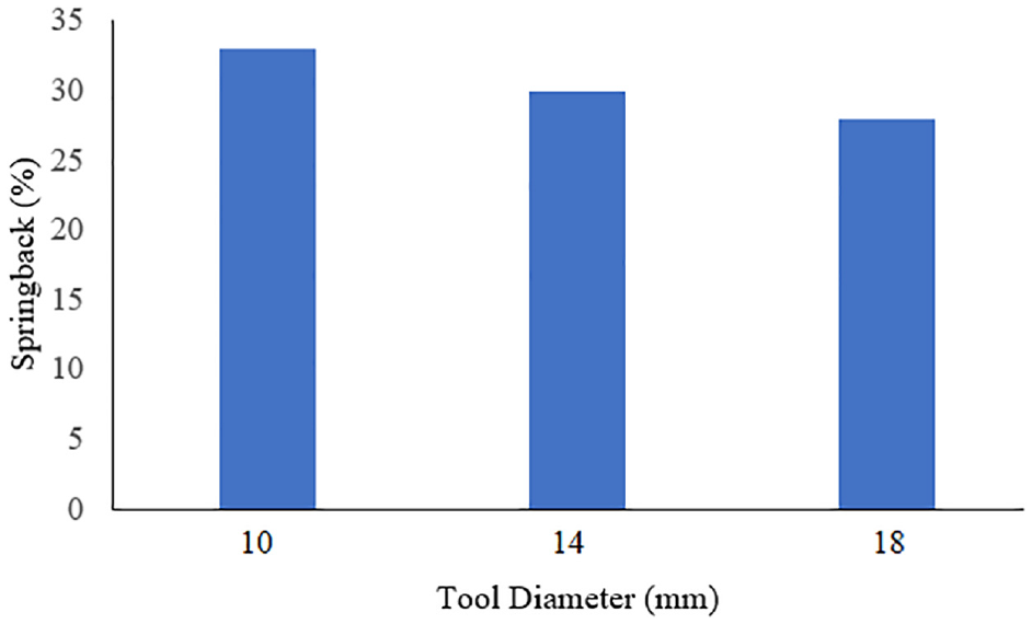
Figure 11 depicts the influence of the tool diameter on spring-back for the straight wall at 25°C. A decrease in spring-back was observed as the tool diameter increased. The reason for this is shown schematically in Figure 12. During the forming process, the tool–workpiece contact point moves towards the tool centre. This shift is greater for tools with larger diameters and thus creates a larger bend angle at the end of the forming stage, provided that the tool path is identical for the tools. As shown in Figure 12, with increasing the diameter of a tool, the bending angle difference
Effect of tool diameter on spring-back at 25°C.
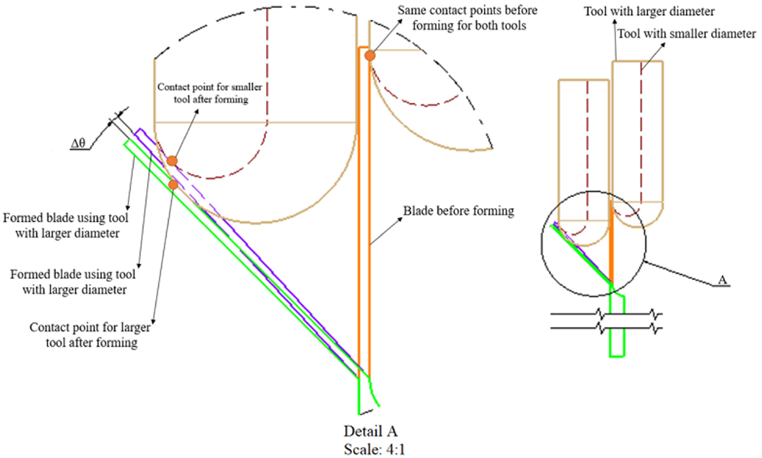
Contact point shift for two tools with different diameters.
Figure 13 shows the predicted plastic strain for two identical elements with tools having diameters of 14 and 18 mm. At the beginning of the forming operation, the increase in plastic strain was similar for both tools. However, as the forming process continued, the plastic strain magnitude increased with increase in tool diameter, resulting in a larger bend angle.
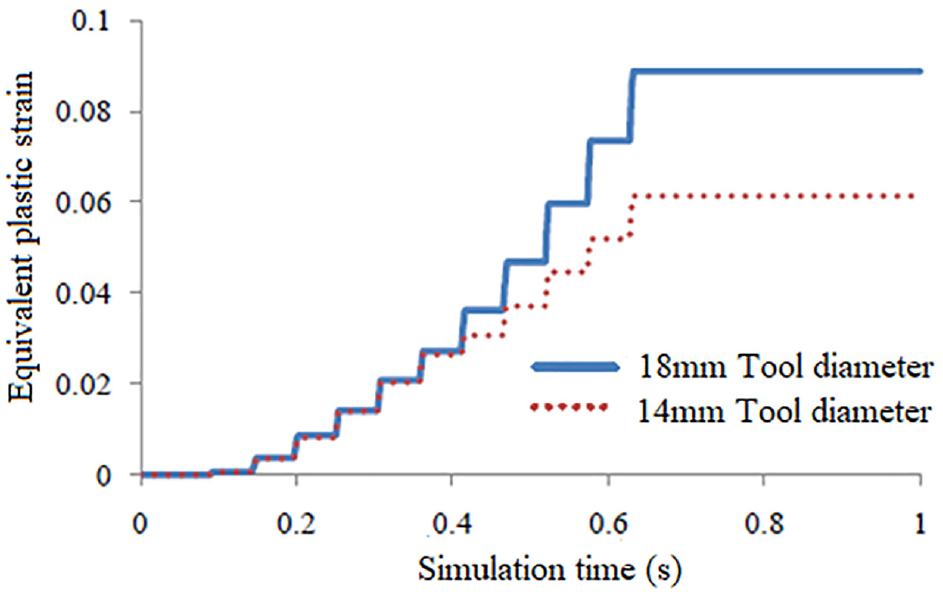
The effect of tool diameter on equivalent plastic strain.
Effect of forming temperature on spring-back
Figure 14 depicts the effect of forming temperature on spring-back. The figure shows that spring-back significantly decreases as the temperature increases. At high temperatures, the flow-stress level of aluminium alloys decreases. 16 During plastic deformation, an amount of energy is required to break the interatomic bonds in metals so that dislocations move. The energy is usually supplied by the external force and the thermal vibration. At high temperatures, the vibrational amplitude becomes larger, so the plastic deformation can occur at a lower stress level, which decreases the spring-back amount. Furthermore, the spring-back decreases because of the stress relaxation. The residual stress after forming decreases with time, and the rate of stress relaxation becomes larger at higher temperatures, which decreases the spring-back.
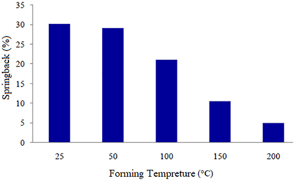
Influence of forming temperature on spring-back for tool with 14 mm diameter.
The results of the study on straight wall bending suggest that to minimise spring-back, the forming temperature as well as the tool diameter should be chosen as large as possible. It should be noted that the increase in temperature is limited by the recrystallisation temperature, as microstructural changes occur at higher temperatures.
Development of twisted blade
Tool path
Figure 15 shows the blade fabricated in the present study using DMP. The blade has a curved surface that cannot be fabricated using the tool path, like the one used in the bending of the straight wall workpiece. For an accurate product, the forming tool should traverse the entire wall surface. The preferred method for tool path generation is the ‘z-height-based slicing algorithm’. In this algorithm, the surface of the product is formed layer by layer by slicing the surface of the product in the vertical direction (z-direction). The tool forms one slice of the surface during each increment. The tool path is shown on the blade in Figure 15. However, this method can cause problems in the upper edge of the blade. One problem is that tool marks are usually observed at the edges as the tool leaves and re-enters the workpiece. Another problem occurs at the top of the blade, where the forming path is relatively short. In this region, the wall might be deflected away from the tool during forming instead of being plastically deformed to the final shape. The unreformed portion disturbs the tool at the next forming increment.
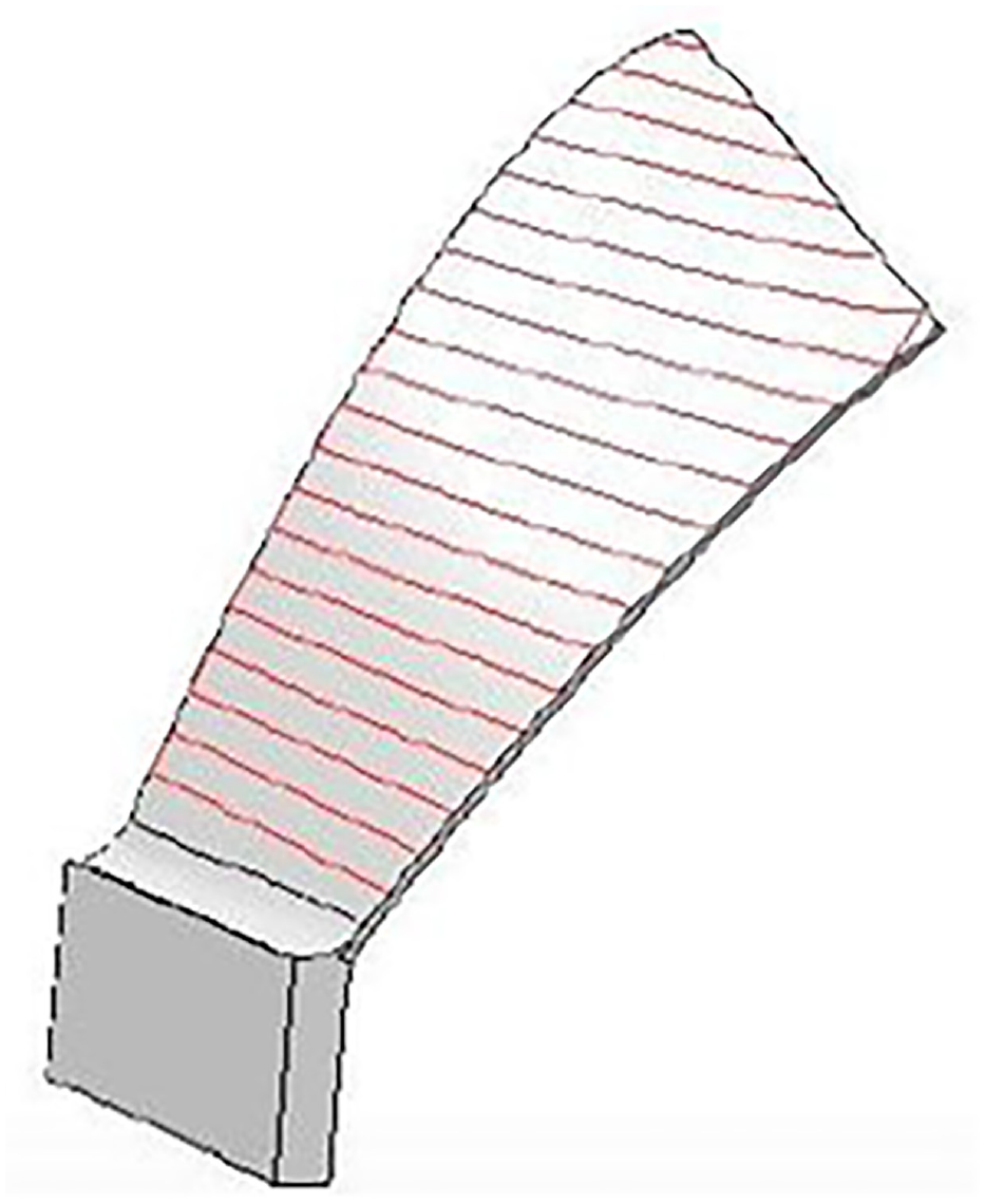
Tool path generated by z-height based slicing algorithm.
To solve the abovementioned problems, a ‘feature-based algorithm’ was used to create the tool path. The algorithm has been described in detail by Lu et al. 17 In this algorithm, the tool path is created using the distance between the surface points and the surface critical edges instead of their heights. It was shown that a better surface quality, geometrical accuracy and shorter tool path can be obtained using this algorithm. This algorithm is especially beneficial for asymmetric geometries with non-horizontal edges. Figure 16 shows the tool path generated for the blade using a feature-based algorithm.
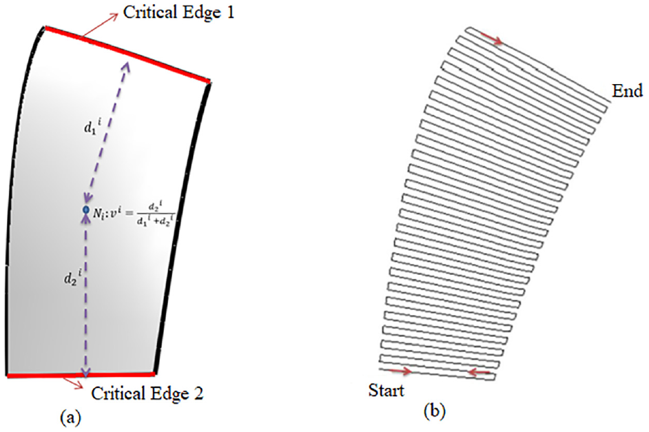
(a) Calculation of a node Ni from one edge and (b) tool path generated by feature-based algorithm.
Forming process and equipment
Figure 17 shows the blade forming process. To minimise spring-back, the largest tool diameter and the highest temperature were used. A hemispherical tool with a diameter of 18 mm was used, and the forming temperature was set to 250°C near the root of the blade. The temperature was kept fixed during the forming operation using a thermocouple. A two-point incremental forming strategy was used to increase dimensional accuracy. In this strategy, a die is used to support the workpiece from the opposite side of the tool.
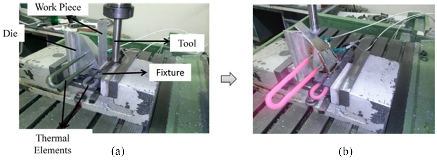
Forming equipment for the curved-surface blade: (a) before forming and (b) during the forming stage.
During the initial tests, it was observed that the upper portion of the blade was not properly formed into the desired shape owing to the lower temperature and larger spring-back of the region. Therefore, an extra heating element was placed within the die to compensate for the heat loss, and the temperature of the region was checked and maintained near 250°C using a thermocouple. The forming increments were extended beyond the top edge of the product. These strategies helped to form the top edge of the blade more accurately. A photograph of the final product is shown in Figure 18.
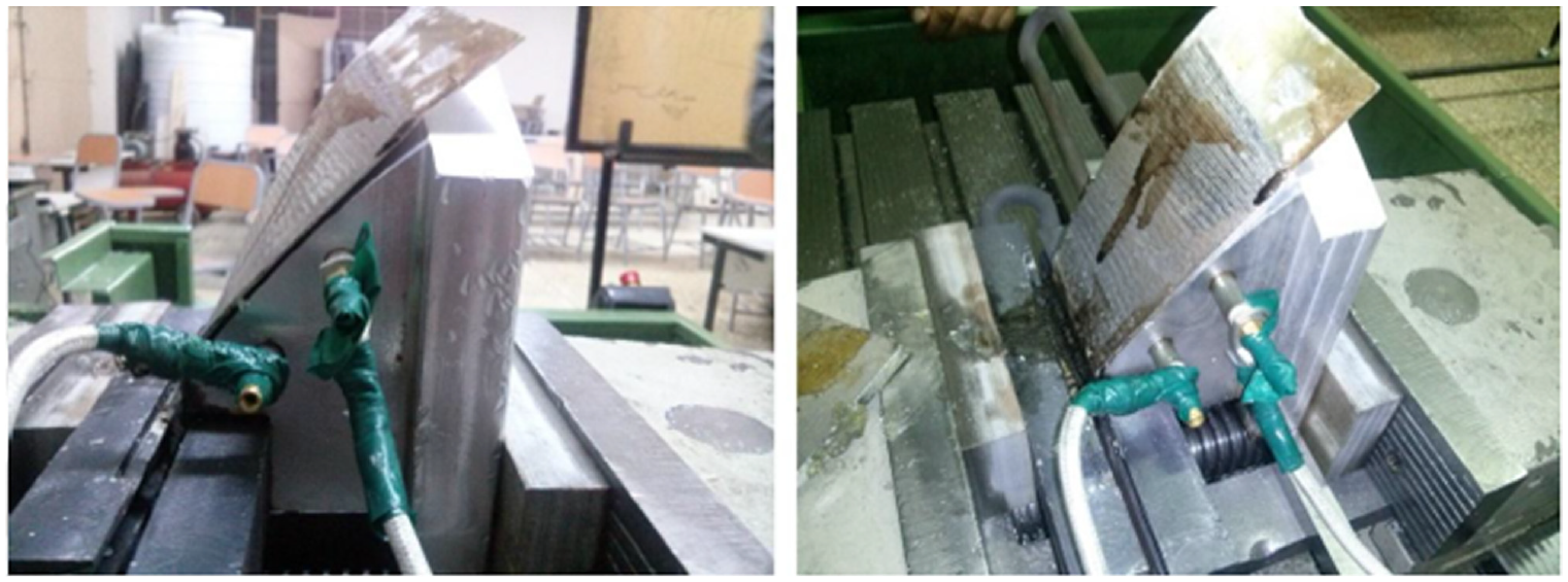
The final product fabricated by DMP-bending mode.
Dimensional accuracy
To evaluate the dimensional accuracy of the product, a SOLUTIONX Rescan CS Plus 3D scanner was used to generate a point cloud of the product. The data were used to create a CAD model of the final shape, as shown in Figure 19.
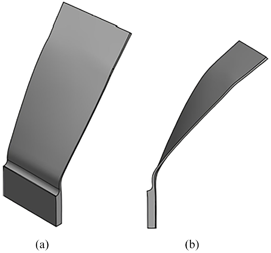
CAD model of the final blade after spring-back: (a) isometric view and (b) side view.
The deviation of the product’s surface from the ideal surface was measured using the Geomagic Qualify software package, as shown in Figure 20.
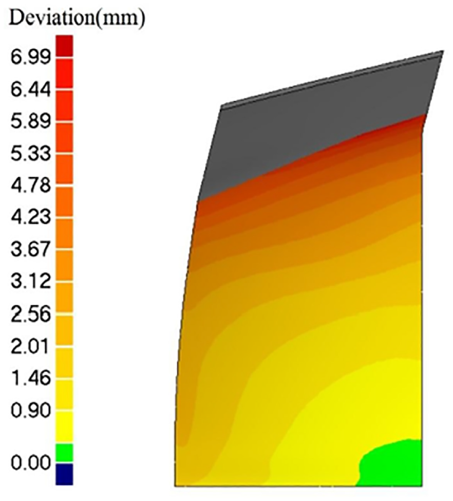
Deviation of the fabricated geometry from the ideal geometry.
The software measures the distance of each point of the product surface from the nearest point on the ideal surface. The grey area is the extended portion of the wall, which does not belong to the ideal geometry. The following can be inferred from the figure:
(1) The dimensional accuracy decreased with increase in height owing to the absence of constraints at the top edge of the blade.
(2) The dimensional accuracy decreased from left to right. This is because of the different curvatures of the left and right edges. By increasing the edge slope, the dimensional accuracy decreased.
Moreover, the deviation average and standard deviation of the product are equal to 2.22 and 2.65 mm, respectively. The frequency of deviations is shown in Figure 21. It can be seen that the deviation range of 1.643–2.052 mm is the most frequent range of deviation of the product’s points. Finally, it was concluded that the spring-back phenomenon cannot be eliminated because there exists an elastic component of deformation, which gets released during unloading after plastic deformation. However, it can be reduced if proper techniques, such as those used in this study, are employed. To increase the dimensional accuracy, spring-back compensation methods such as over-bending needs to be employed; however, this is beyond the scope of the current work.
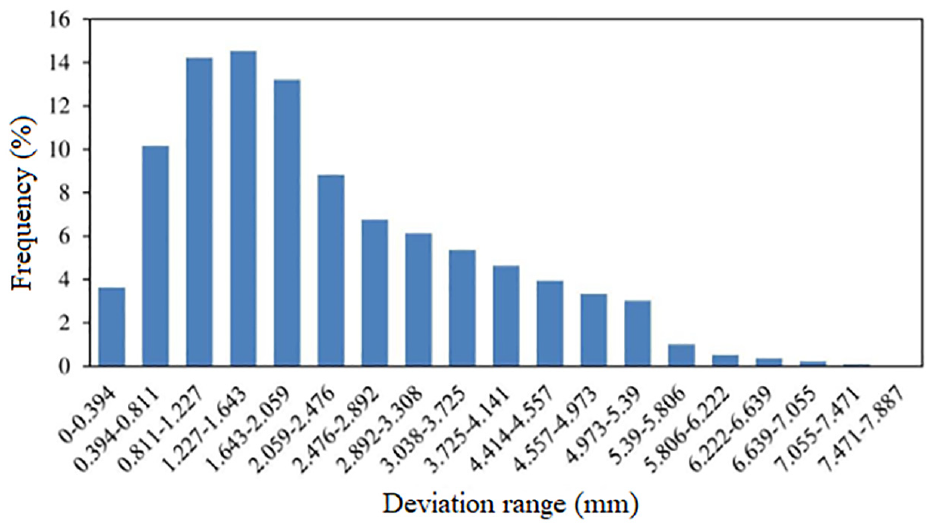
Frequency of deviation ranges.
Conclusion
In this work, we investigated the effect of process parameters on the dimensional accuracy of the hybrid forming-machining process for straight and twisted blades. Significant findings are as follows:
During the straight blade forming, a tool with a larger diameter has a larger bending angle at the end of the forming stage. However, increasing the tool diameter from 10 to 18 mm decreased the spring-back amount from 33% to 28% at 25°C. The bending angle and spring-back angle were inversely correlated.
It was found that the forming temperature had a greater effect on the spring-back of the wall. The spring-back amount decreased from 30% to 5% in temperatures from 25°C to 200°C. Due to the thermal softening phenomenon reduces the material strength, which in turn decreases the spring-back.
For the hybrid forming-machining of twisted blade, the dimensional accuracy decreased with an increase in the height of the wall, because the upper edge of the blade is not constrained.
For the twisted blade, the edge slope affected the dimensional accuracy. The dimensional accuracy decreased at the left side where the edge slope is larger compared to the right side with a small edge slope.
Footnotes
Declaration of conflicting interests
The author(s) declared no potential conflicts of interest with respect to the research, authorship, and/or publication of this article.
Funding
The author(s) received no financial support for the research, authorship, and/or publication of this article.