
Abstract
In this research, SiC/Al A413.1 functionally graded materials (FGMs) were fabricated by the vibrating centrifugal solid particle method (VCSPM), and the effects of the SiC particles on the microstructure and thermo-mechanical properties of an A413.1 aluminium alloy were investigated. The benefits of a vibration during centrifugal casting of FGMs are illustrated. After designing and fabricating the centrifugal casting machine, cylindrical FGM specimens were produced using the centrifugal solid particle method (CSPM) and VCSPM. This study used SiC particles with an average particle size from 50 to 62 μm as reinforcements to fabricate A413.1-10 wt% SiC functionally gradient composites at three annular mould speeds (900–1500 and 2100 rpm) and with or without a vibration of the mould. The Brinell hardness was measured; the yield strength (YS), ultimate tensile strength (UTS) and Young’s modulus (E) were determined by tensile testing; the density was determined by the Archimedes method; and the thermal expansion coefficients were measured with a dilatometer. A comparison of the samples produced by the conventional method and VCSPM shows a significant reduction in the porosity and an increase in the distribution gradient of the reinforcing particles for the VCSPM case. It can be concluded that in both processes, the mechanical and thermal properties improved in most cases by moving from the inner radius to the outer radius because of the movement of particles towards the outer radius from the centrifugal force. The results also show that the use of a vibration dramatically increased the rate and speed of migration of gas bubbles towards the inner radius, and the mechanical properties (hardness, YS, UTS and E) improved by moving from the inner to outer radius due to an increase in the percentage of silicon carbide particles. Upon increasing the velocity and using the VCSPM, the slope of these changes becomes steeper than those for the vibration-free mode and at low rotation speeds.
Keywords
Introduction
In recent years, the need for structural materials with a high strength, toughness, impact resistance, hardness, yield strength (YS) and chemical and mechanical corrosion resistance in addition to a low weight and low cost of production has led to the development of functionally graded material (FGMs). In FGMs, the composition and properties change gradually with the geometrical position. These changes in the properties, composition, and microstructure have led to the design and production of many engineering parts. Several processes have been reported for FGM fabrication. 1 Primary production methods are divided into two main types: powder processes2–6 and melted metal techniques.7–13 One of the techniques involving melted metal is the centrifugal casting process that has been specifically adapted to the production of cylindrical parts. The fabrication of the FGMs by centrifugal casting can be classified into two categories based on the processing temperature of the master alloy: the centrifugal solid-particle method (CSPM)7–11 and the centrifugal in situ method (CISM).12–15
If the processing temperature is higher than the melting temperature of the matrix metal and the dispersing phase, centrifugal force can be applied during solidification to the nucleated intermetallic compound and molten matrix. The solidification process is similar to the production of an in situ composite using the crystallisation phenomenon and is therefore referred to as the CISM. 16 During CSPM, the dispersed phase remains as a solid in a liquid matrix during centrifugal casting. 17 During this process, the centrifugal force is applied to a homogeneous molten composite, and the powder particles are graded in the radial direction of the cylinder. Zhu et al. 18 showed that with the addition of SiC nanoparticles, the microstructure of a 6082 aluminium alloy was refined; there was up to a 30.55% grain refinement compared to that for a 6082 aluminium alloy without the addition of the SiC. The particle distribution can be controlled depending on various parameters, such as the angular speed, particle density and molten temperature. Gao and Wang 19 investigated the mould rotational angular velocity on the SiC particle distribution. They found that a higher rotational speed gave a thicker particle-denuded region. The 500 rpm case did not provide enough centrifugal force to segregate the particles before solidification, and therefore, there was not a significant gradient generated in the solidified part. For the mould rotated at 1500 rpm, three separate regions formed in the specimen, including a particle-free region, gradient region and packed region. The principal advantages of the centrifugal casting method are its good mould filling and reasonable microstructural control, which usually result in excellent mechanical properties. 20
One of the most critical factors for the production of composite parts is an understanding of their thermal and mechanical properties. However, considering the mechanics of FGMs, most of the research to date has concentrated on theoretical modelling and analysis with little experimental testing. 21 In most experimental works, the hardness14,15,21,22 has been investigated. In the case of other mechanical and thermal properties, little experimental work has been done. The effect of SiC particle reinforcement on the strengthening of A359 Al alloys was studied experimentally by tensile testing specimens with different SiC contents by Rodrıguez-Castro et al. 21 and Owoputi et al. 23 In another work by Aydın et al., 4 the Young’s modulus (E) and YS for Al/SiC FGMs has been investigated. The use of a vibration during the production of FGMs has not been studied. However, it is well documented that applying a mechanical vibration to a mould during solidification has a profound effect on the microstructure and mechanical properties of castings.24–27 Applying a vibration to a solidifying eutectic Al-Si alloy leads to microstructural changes in the eutectic region and a dendritic structure in the aluminium. The vibration successfully broke the dendritic structure into small islands of aluminium. 24 Fisher 28 used a vibration treatment on an LM6 alloy (Al–12.3% Si) and showed a reduction in the grain size, and the primary dendrites were also reduced in size. Kocatepe and Burdett 29 applied a vibration to two types of LM6 alloys, one with a grain refiner and sodium and the other with no additions. They have found that the grain size of the unmodified alloy was reduced by 52% by subjecting it to a vibration, while the grain refinement was 76% for the modified alloy.
This article presents the microstructure, composition gradient, and thermal and mechanical properties for an Al-based FGM fabricated by CSPM and the vibrating centrifugal solid particle method (VCSPM), which is proposed in this research. At first, a suitable centrifugal casting machine was designed and fabricated to control the mould and furnace temperatures, mould annular speed and stir speed of the melt to obtain profiles with different particle distributions. Then FGM cylinders with an A413.1 aluminium matrix reinforced with SiC particles were fabricated by both methods. Test samples were extracted from the fabricated FGM parts and used to determine the microstructure, particle distribution, hardness, density, YS, E and thermal expansion coefficient, which were measured and compared for different radii of the produced components. This study evaluated the effects of annular speed and a vibration on the particle distribution and mechanical and thermal properties.
Experimental procedures
Materials
The matrix material and reinforcing particles used in this study were an A413.1 aluminium alloy and SiC with a median particle size from 50 to 62 µm with a density of 3.21 g/cm3, respectively. Figure 1 shows the used SiC particles and energy-dispersive spectroscopy (EDS) patterns with a 99.9% purity. The SiC powder was preheated for3 h at 900°C, which resulted in the formation of a surface oxide and increased wettability. The matrix alloy was an Al-Si alloy (Al413.1 aluminium alloy) with a composition (by weight determined by Spark Emission Spectroscopy method) of 11–13% Si, 0.6% Fe, 0.1% Cu, 0.05% Mn, 0.03% Mg, 0.05% Ni, 0.05% Zn, 0.05% Sn and 0.1% of other elements. The density of the molten matrix of Al413.1 was approximately 2.4 g/cm3. In the Al413.1 alloy, Mg provided age hardening, and Si was present in the microstructure of the age-hardened alloy as both an interdendritic eutectic and a Mg2Si strengthening precipitate. 30 Si improved casting characteristics, such as the fluidity, hot tear resistance and feeding.
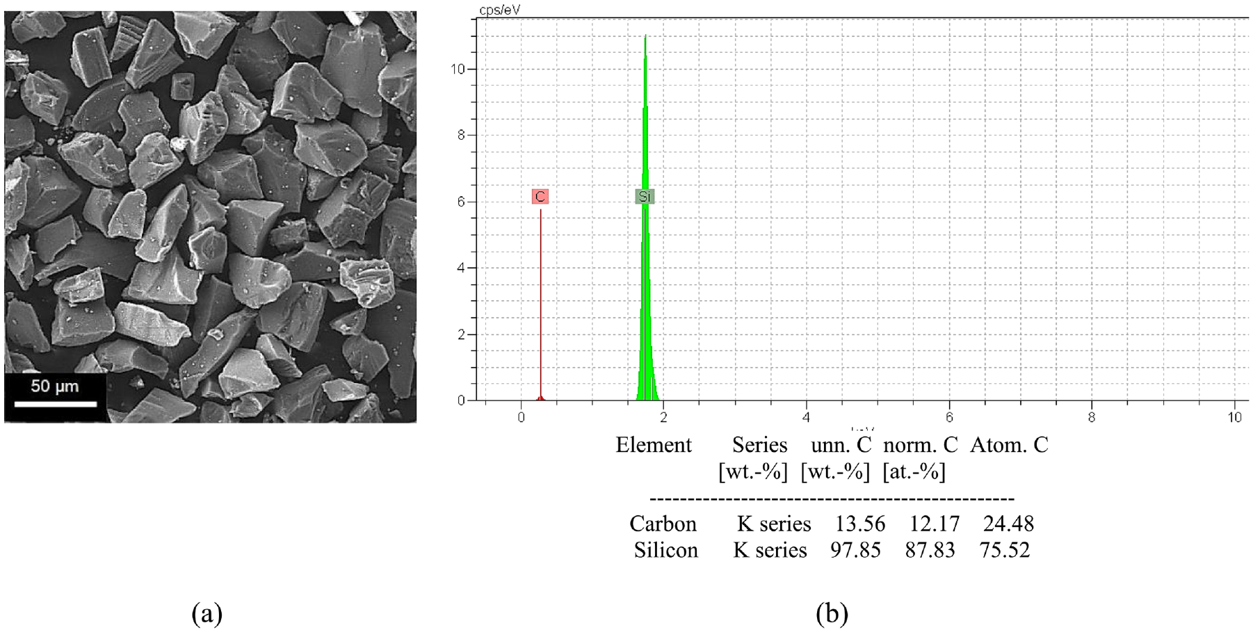
(a) SEM image and (b) EDS analysis of reinforcing SiC particles.
Furthermore, the presence of Si in this alloy reduced reactivity with SiC during the centrifugal casting process. 31 The addition of 1 wt.% Mg powder as a wettability-promoting agent enhanced the wettability between the particles and aluminium and decreased the porosity32,33 and incorporation of ceramic particles; the Mg acted like a surfactant that reduced the aluminium oxide coating by binding to the oxygen in it. 34 Due to comments by the researcher, 1 wt.% Mg powder was added to the melt in this work.
Centrifugal casting machine
In this research, a horizontal centrifugal casting machine was fabricated to produce FGM components. It consisted of an alloy melting muffle furnace, inlet, mould, centrifugal system, heating coil, control system and manual transmission of the molten discharge system, which are shown in Figure 2.
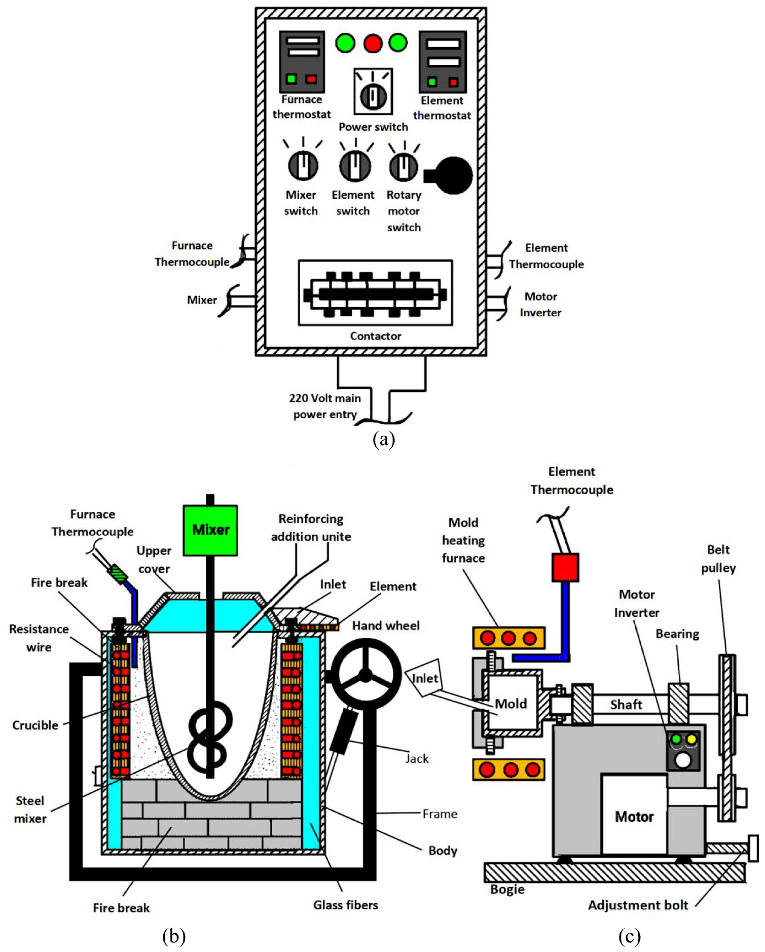
A schematic representation of the horizontal centrifugal casting machine used for fabrication of FGM components:(a) electrical panel, (b) melting furnace and (c) horizontal centrifugal casting machine.
A batch of approximately 1 kg Al A413.1 alloy lumps, cut from the master alloy, was melted in the crucible furnace to clean and remove any surface impurities before it was used. The furnace temperature was first raised above the liquidus to melt the alloy completely and cooled to just below the liquidus (640°C) to keep the slurry in a semisolid state. To prevent particle clustering in the composites, 1 wt.% magnesium was mixed with 10 wt.% SiC preheated reinforcement based on literature reports.35,36 El-Galy et al. 37 showed that by increasing SiC reinforcing particles to more than 10 wt.%, the hardness, ultimate tensile strength (UTS) and wear resistance in the outer layer decreased. The mixture of magnesium and reinforceming particles was fed at a constant rate to avoid coagulation and segregation. 38
After stirring for 5 min, the semisolid stage slurry was reheated and held at a temperature of 780°C to make sure the slurry was fully liquefied. The spiral stainless steel stirrer was designed to produce an adequate homogenous particle distribution throughout the matrix material. An internally threaded 50 cm long stainless steel rod was fitted over this stirrer. The stirring speed and duration should be optimally selected to provide complete melt homogenisation without the formation of particle clusters. A lower amount of stirring time causes more air bubbles to enter. 34 On the other hand, the stirring speed should not be too high because this causes porosity in the microstructure due to oxide skins, gases and contaminants due to vortex formation. 39 The stirrer rpm was then gradually lowered to zero, and then, aluminium dross was removed from the surface of the molten metal. Once the melt was ready, the furnace was rotated by a manual transmission 90° around the gearbox axis (with a hand wheel), and the molten metal was allowed to flow out of the rotating melting chamber. The melt was then poured into a CK15 (1015) steel rotating mould with a capacity of 800 g of molten metal through the inlet. Both the inlet and the mould were preheated to approximately 500°C before the melt was poured into the mould. After the molten alloy was poured into the mould cavity, the mould was rotated for 120 s to distribute the particles in the radial direction of the cylinder. In the last step, the mould was cooled to atmospheric temperature, and then, the prepared sample was removed from the mould.
In this study, the samples were produced at three different rotation speeds (900, 1500 and 2100 rpm) for the moulds for CSPM and VCSPM. For VCSPM, the unbalanced weight method was used to obtain a vibration frequency for particle grading. For this purpose, a 5 g weight mass was attached to one side of the mould, resulting in an unbalanced weight and vibration. The samples were cast in two modes: with and without a vibration. Other factors, such as the matrix and reinforcement composition, crucible and propeller geometry, reinforcement treatment, preheated mould, inlet, melt temperature, stirring speed and mould material, were kept constant.
Specimens and experiments
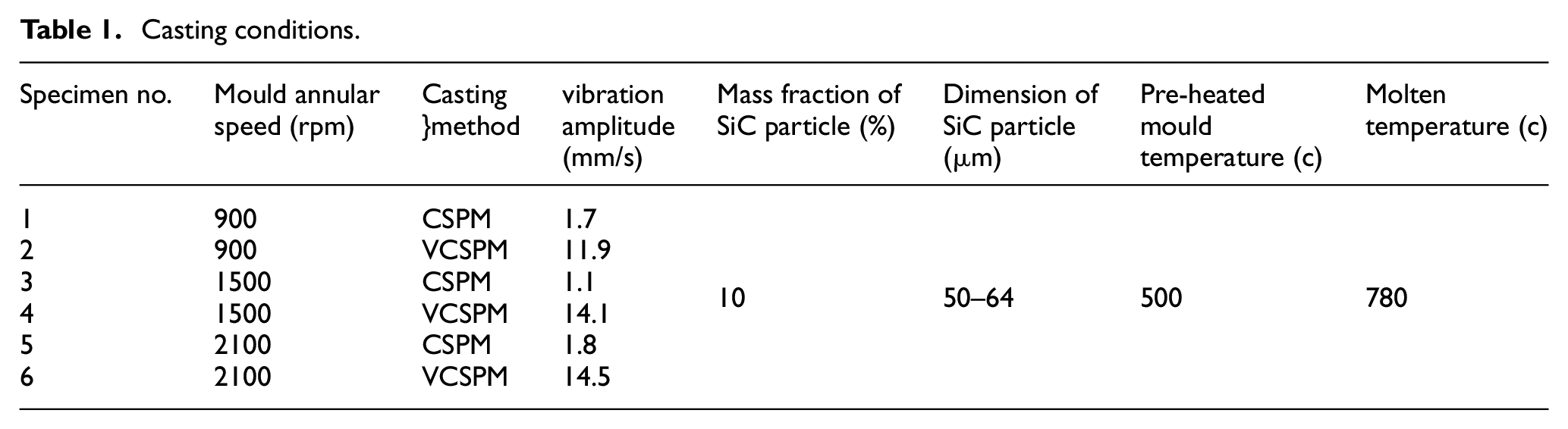
In this study, thick-walled FGM cylinder casts with an outer diameter of 76 mm, a thickness of over 22 mm, and a length of 74 mm were prepared with a powder of pure SiC and Al A413.1 CSPM and VCSPM were used. The key parameters were the mass fraction of SiC (10 wt.%), mould annular speed (900–1500 and 2100 rpm), and vibration of the mould (with or without).
The addition of a mechanical vibration was used to investigate the effect of vibration on the particle distribution and mechanical properties. For this purpose, a weight of 5 g was attached to one side of the mould, which led to a mass nomination defect (unbalance defect). The mass nomination defect in rotating equipment creates an unbalanced force when the geometric centre of the rotating shaft does not correspond to the centre of mass, which in the presence of centrifugal force, causes a force or vibratory motion to be applied to the bearings. To study the vibration amplitude in the modes with and without unbalancing defects in the radial direction, a CMX9 vibrometer device from the ADASH Company was used. An example of a frequency of rotation and vibration amplitude measured at 1500 rpm is shown in Figure 3. The casting conditions are summarised in Table 1.
Casting conditions.
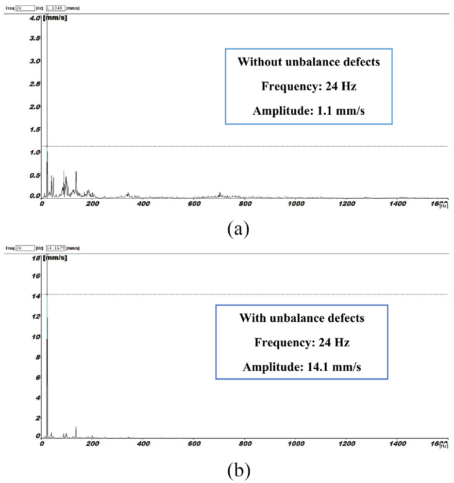
Radial vibration amplitude in the front bearing in a centrifugal casting machine: (a) balanced frequency spectrum at 1500 rpm (24 Hz) and (b) frequency spectrum in unbalance state at 1500 rpm (24 Hz).
After machining, the required test specimens (Figure 4) were extracted by a wire cutting machine. A radial cross-section was cut from each thick-walled FGM cylinder for microstructural observations. The specimens were mechanically and chemically polished. Then, the composition gradients in the specimens were characterised by optical microscopy from metallographic samples prepared by standard metallographic polishing techniques. The microscopic observations were done quickly without any etching because the colours of the SiC particles and the Al matrix were different. Then, the microstructures of the fabricated FGMs were observed using scanning electron microscopy (SEM). EDS analysis was also performed to reveal the elemental composition gradients in the samples. Hardness testing was performed in the radial direction of the specimens. From each cylinder in the radial direction, four tensile test specimens were extracted, as shown in Figure 4. Care was taken to avoid using material close to the edges of the blocks due to possible edge effects. Four tensile specimens were machined to standard dimensions (Figure 4) (ISO 6892-1). Machining of the specimens was done with a wire cutting machine.
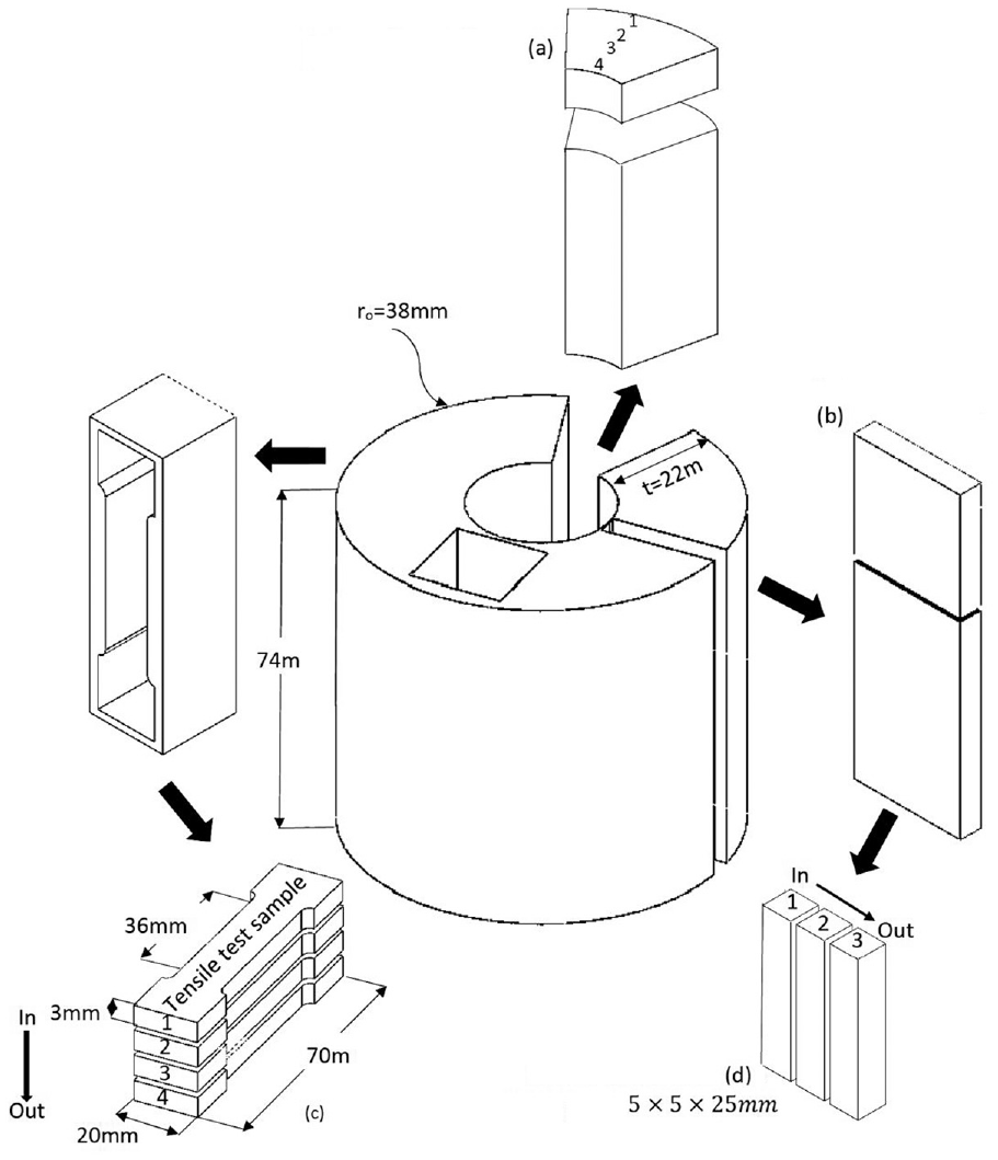
Schematic of where the test specimens were cut:(a) metallographic sample, (b) hardness sample, (c) tensile test sample and (d) dilatometry sample.
A dilatometer (Dil 101-HT) was used to obtain the thermal expansion coefficients. As shown in Figure 4, samples one, two and three were extracted in the radial direction at 7, 12 and 17 mm (5 × 5 × 25 mm) away from the inner radius, respectively.
Results and discussion
Morphology
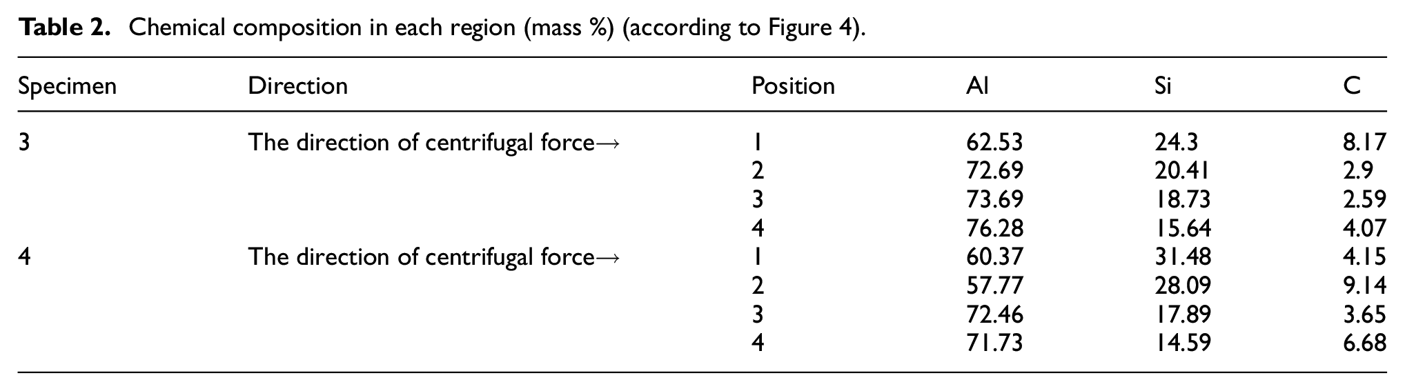
The microstructure of the specimens fabricated by CSPM and VCSPM at rotation speeds of 900, 1500 and 2100 rpm as observed by optical microscopy (Sinowa Upright Metallurgical Microscope) are shown in Figures 5 and 6. In this figure, at four points shown in Figure 4, imaging was performed at a 10× magnification. The microstructures are shown for the outer periphery (upper images) towards the inner periphery (lower images) at different positions (2, 7, 14 and 20 mm). The relative magnitudes of the densities 22 determined the movement direction of the particles being acted upon by the centrifugal force. Due to the higher density of the SiC particles than the Al melt, these particles moved towards the outer radii of the hollow cylinders when they were acted upon by the centrifugal force.
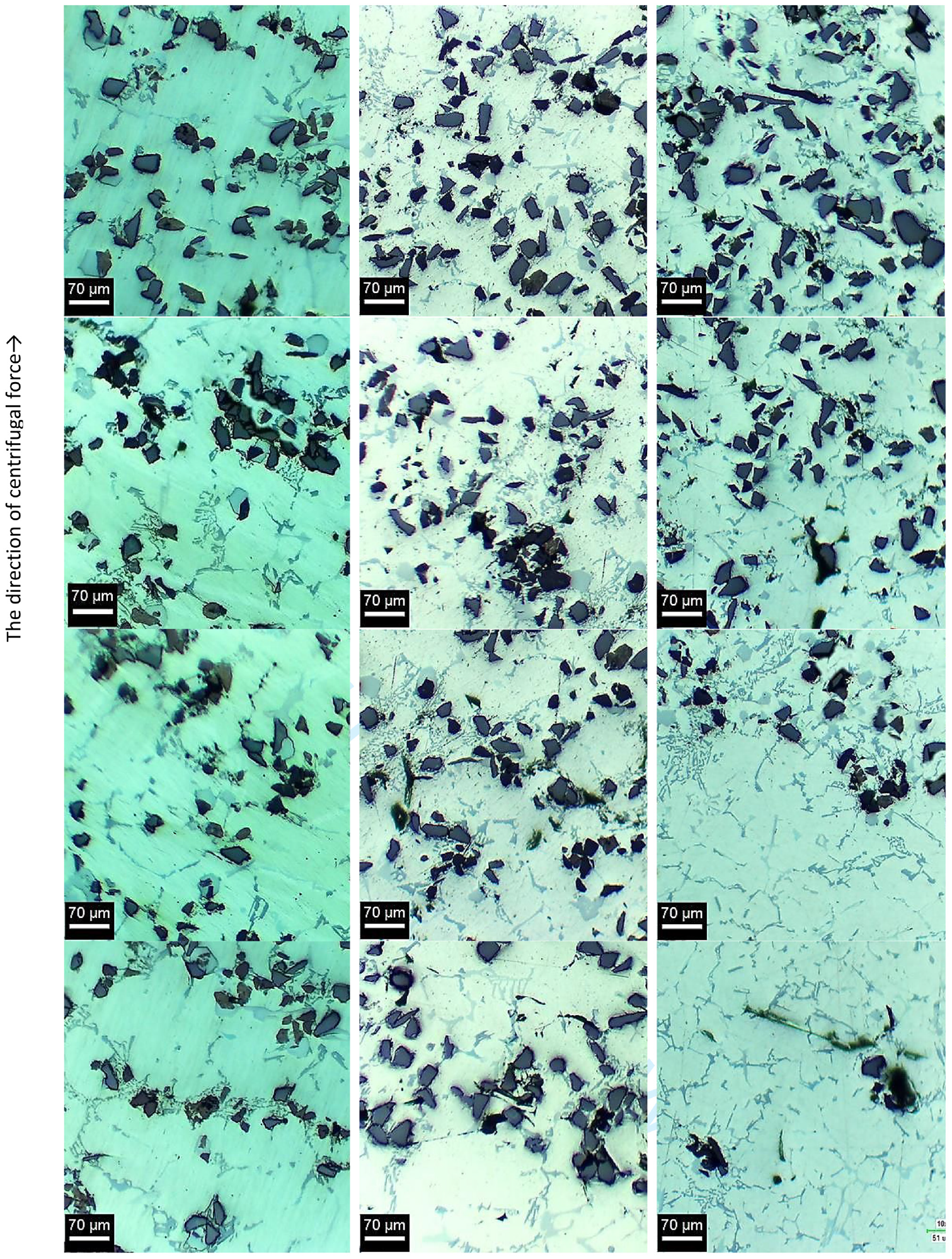
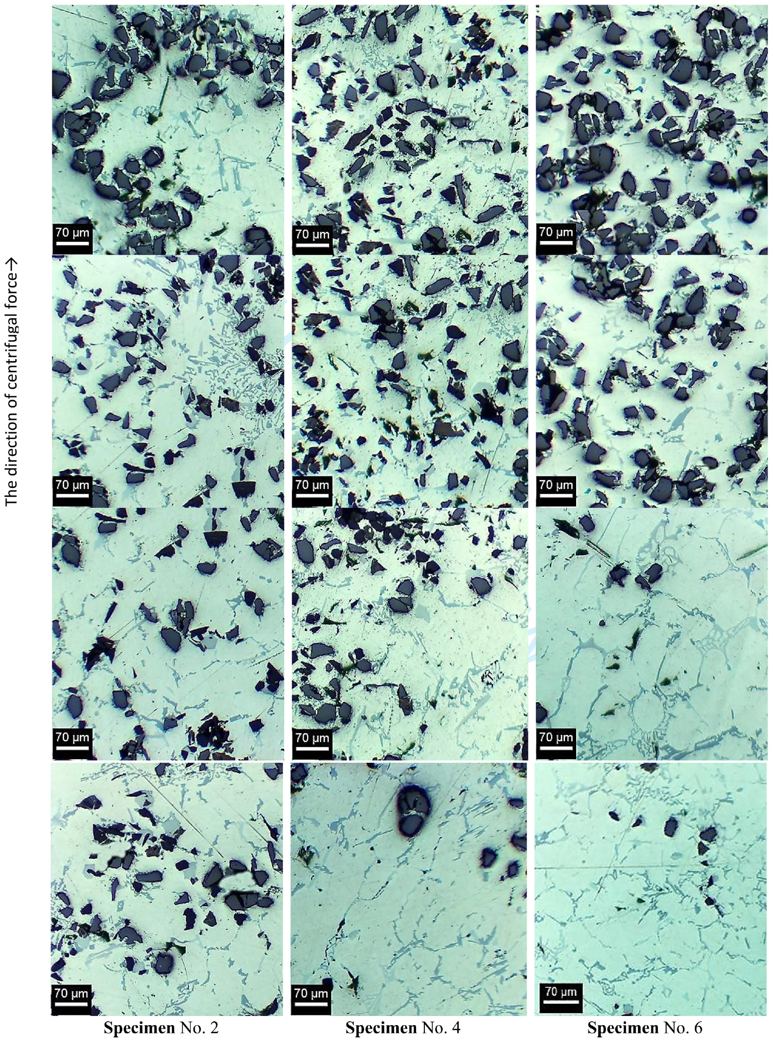
For all specimens, the outer layers of the casting showed a higher concentration of SiC particles than the inner layers of the casting. This result is in agreement with previous studies reported for FGMs processed by centrifugal casting.9–11,21–23 The image analysis results depicted in Figures 5 and 6 show that with increasing rotational speed, the concentration of the SiC particles in the outer layers increased, and the volume fraction of SiC in the inner layers at high rotation speeds decreased to zero.
By subjecting homogenous composite melts to the maximum rotational speed, a maximum volume fraction of SiC was obtained in the outer layers and led to improved specific properties, such as the hardness and wear resistance.10,17,21
There was a sharp transition between the SiC enriched and depleted zones in the VCSPM specimens, whereas a gradual or smooth transition was seen in the CSPM specimens. It was also observed that a vibration caused faster migration of the SiC particles towards the outer radius. On the other hand, vibration has a very favourable effect on the movement of gas bubbles towards the inner radius. With an increase in the rotational speed due to an increase in the vibration amplitude, the effects of the vibration on the casting became much more evident. The other significant observation of the matrix microstructure involved the presence of a higher amount of eutectic silicon phase at the inner periphery of the casting (sample No. 5 in Figure 6). After solidification of the primary aluminium, the remaining eutectic liquid moved towards the inner periphery, leading to a higher amount of eutectic silicon near the inner periphery. Moreover, a modified eutectic silicon structure was observed due to the agitation caused by the centrifugal force in the eutectic liquid during solidification, as Rajan et al. 9 concluded.
Figure 7 was taken from the inside edge of an FGM cylinder produced at a rotational speed of 1500 rpm with and without vibration (specimens No. 3 and 4) before machining it for parts. An investigation of the inner radius of the cast cylinders indicated the presence of gas pores and a few agglomerated particles. During the mixing process, air bubbles were sucked into the melt via the vortex created by the addition of the SiC powder to the melt in porosity in the FGM. The centrifugal force drove the gas bubbles in the melt to the inner radius of the cast cylinders because of their lower density. The agglomerates comprised partially wetted or non-wetted particles, and lower density gases were also driven to the inner radius. 9 In addition, the movement of large gas bubbles from the outer radii towards the inner radii during rotation can prevent the particles from moving in the opposite direction and move a few particles away. The gas and shrinkage porosities pushed to the inner radius can be removed by machining. It is evident that these effects were exacerbated with the use of a vibration, and the quality of the parts produced increased (Figure 7(a)).
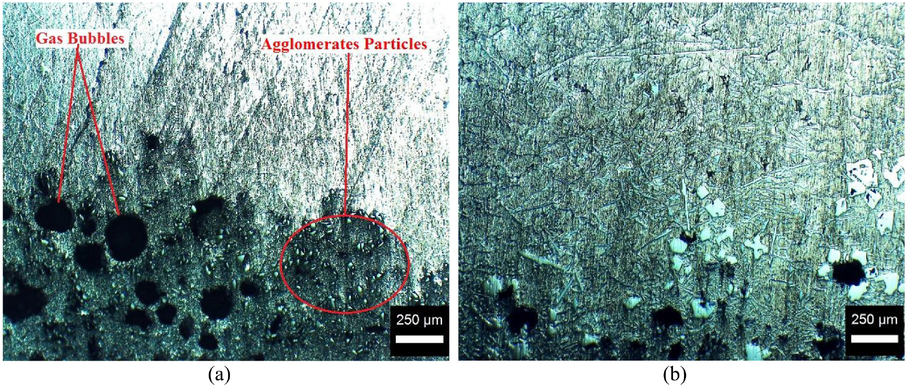
Gas bubbles and agglomerated particles in the inner radius under the same conditions for: (a) VCSP and (b) CSPM.
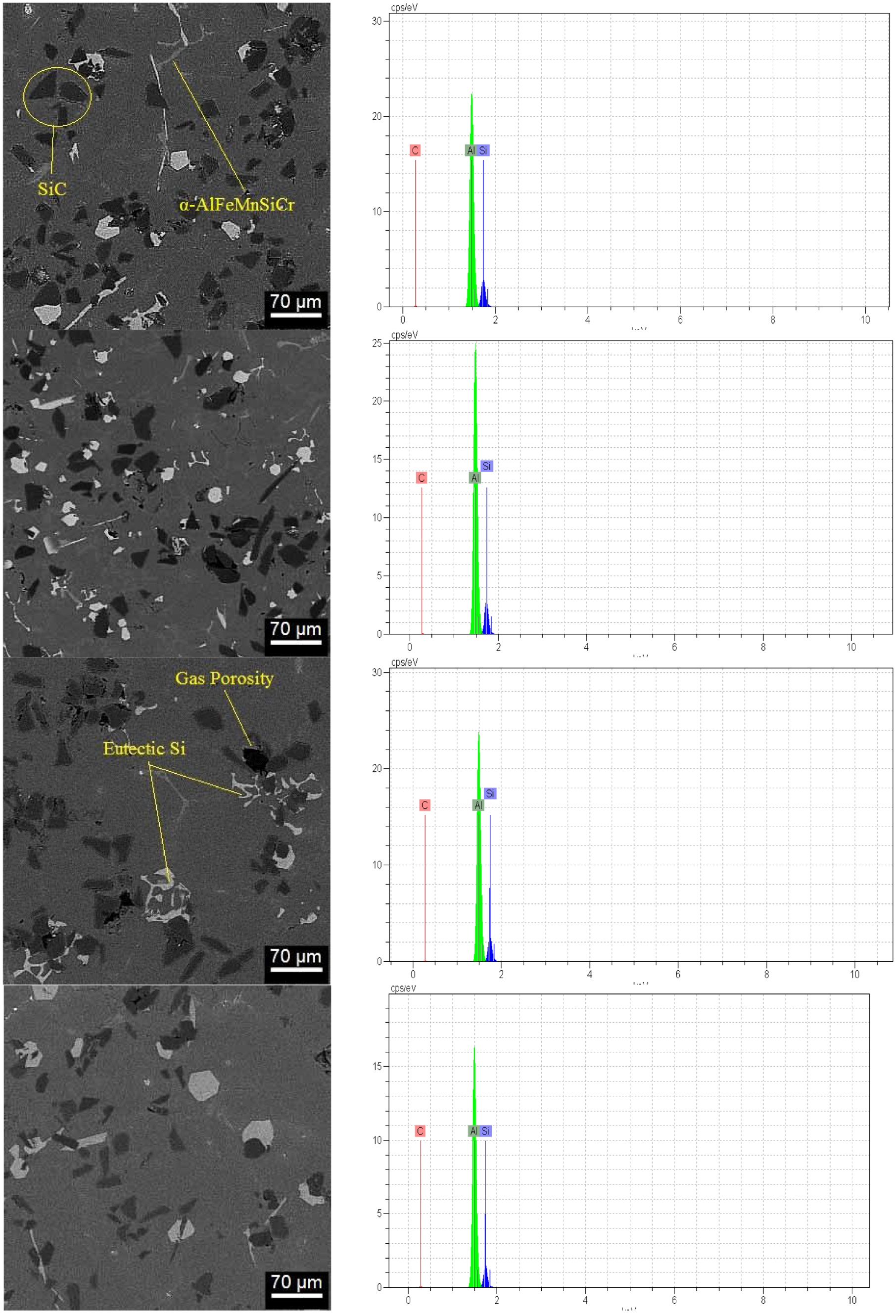
For specimens three and four, scanning electron microscopy (SEM: VEGA\\TESCAN-XMU) images and EDS X-ray dot maps were obtained at four regions (Figure 4) in the direction of the centrifugal force, as shown in Figures 8 and 9. Table 2 shows the results of the energy spectrum analysis for Si, Al and C. The SEM images (Figure 8), EDS analysis (Figure 9) and energy spectrum analysis (Table 2) show that in the FGM components, the percentage of reinforcing particles in the outer layer was much higher than in the inner layer in the VCSPM samples.
Chemical composition in each region (mass %) (according to Figure 4).
The SEM-EDS of specimen 3 (VCSPM) at four regions in the direction of the centrifugal force. The left side shows the SEM image, and the right side shows the EDS result. The horizontal axis shows the accelerating voltage range used for the EDS analysis, kilo-electron-volt (keV) and the vertical axis shows counts per second per electron-volt (cps/eV).
The SEM-EDS of specimen 4 (VCSPM) at four regions in the direction of the centrifugal force. The left side shows the SEM image, and the right side shows the EDS result. The horizontal axis shows the accelerating voltage range used for the EDS analysis, kilo-electron-volt (keV) and the vertical axis shows counts per second per electron-volt (cps/eV).
The composition or number of nanoparticles near and at the surface can be estimated using the EDS technique provided it contained heavy metal ions. The EDS model was used to investigate and identify the particles and phases formed during solidification. Figures 8 and 9 show the presence of intermetallic iron and α-AlFeMnSiCr compound parts in the microstructure. The presence of these phases is generally considered to degrade the quality of castings due to their brittleness and porosity. These phases were formed from the elements present in the matrix alloy and obtained from the dissolution of the stirrer blade during particle mixing. The other significant observation of the matrix microstructure is the presence of a higher amount of eutectic silicon phase at the inner periphery of the casting. This eutectic silicon was due to the high percentage of Si in the aluminium alloy matrix.
Mechanical and thermal properties
The Archimedes’ principle determined the density by the water immersion method. The density of the tensile test specimens (as shown in Figure 4) was first determined by the Archimedes’ method, and then, the tensile test was performed. As expected, the density increased with increasing distance from the inner radius due to an increase in the number of SiC particles in the matrix (Figure 10). This result agrees with previous studies reported for FG composites processed by centrifugal casting. 40 Due to the lack of complete migration of air bubbles in sample one, the density obtained in the inner layer was lower than that of the matrix alloy.
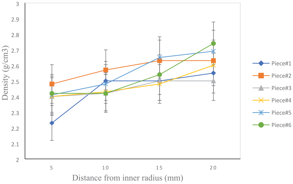
The density of the samples was determined by Archimedes’ method.
The hardness distributions were determined using a Brinell hardness tester with an applied load of 31.25 kgf and 2.5 mm indenter diameter. Figure 11 shows the hardness values measured in the radial direction for parts produced by VCSPM and CSPM. As expected, in all samples, the maximum hardness values were observed at the outer radius due to the presence of the higher volume fraction of SiC particles. Due to the decrease in the percentage of SiC particles towards the inner radius, the hardness also decreased. As the rotational speed increased due to an increase in the centrifugal force, the percentage of particles in the outer radii increased, resulting in a sharper trend, while for the lower rotational speed, it was more uniform. By comparing the hardness results obtained with the vibrating and non-vibrating modes, it was evident that the vibration increased the percentage of particles in the external radii and thus, increased the hardness. As shown, higher hardness values were found in the outer radii for sample six, which had a higher volume fraction of reinforcements due to the vibration and maximum rotational speed. The increase in the hardness in the inner layer of samples five and six was due to the high silicon eutectoid phase.
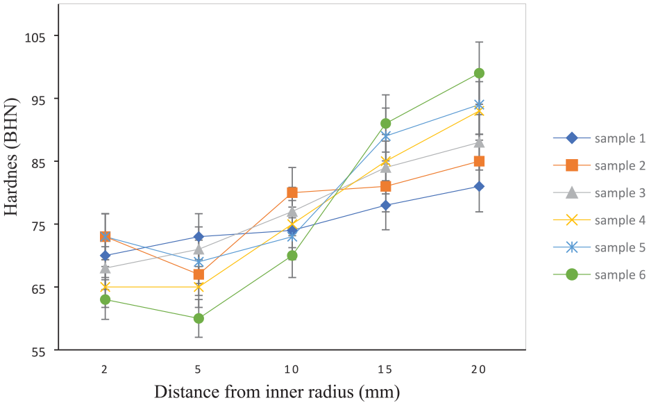
Variation in hardness from VCSPM and CSPM Al (A413.1)-SiC functionally graded composites.
All the tensile tests were performed at room temperature using a SANTAM STM-50 testing machine operating at a constant crosshead displacement rate with an initial strain rate of 10−2 s−1. The 0.2% proof strength (interpreted as the measurable YS), UTS and E were measured for all six as-cast specimens. Four tensile test samples (two series for each test) were extracted (Figure 12(a)). The schematic and dimensions of the samples are included in Figure 4. After performing two series of tests for each sample and deleting the outliers, the YS, UTS and E values were calculated. Figure 12 shows the tensile test results (YS, UTS and E) for six of the fabricated cylinders at four radii in the radial direction. As can be seen, the YS, UTS and E values increased by increasing the number of ceramic particles in the different layers. The maximum YS, UTS and E occurred at the outer radius of sample five with a rotational speed of 2100 rpm and without a vibration.
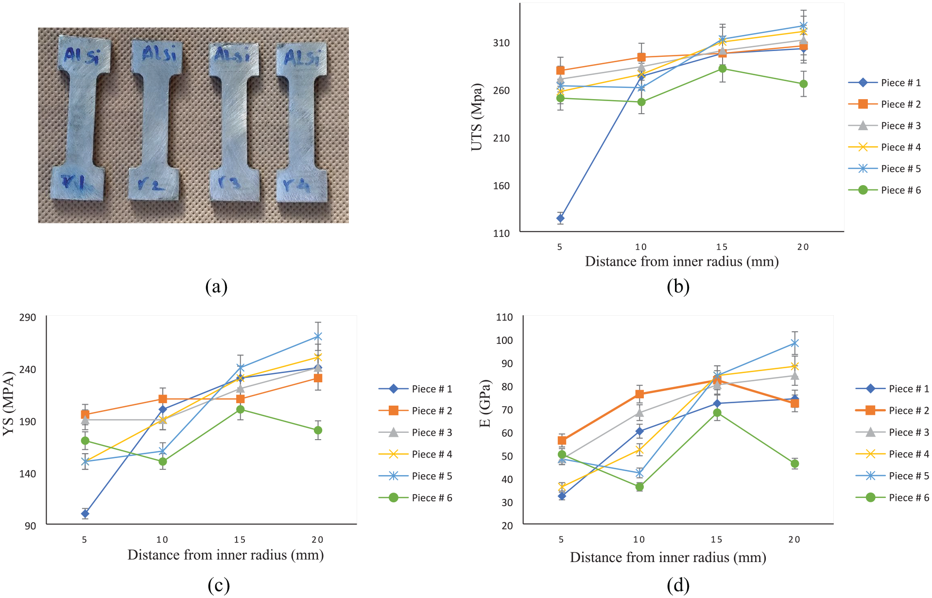
(a) Tensile test samples extracted for each specimen. Mechanical properties of the as-cast samples: (b) UTS,(c) YS and (d) E.
The obtained results are in good agreement with previous works.21,22,37 As previously illustrated in Figure 5, the maximum number of ceramic particles was in the outer radii of sample six, but at the outer layers of the samples, the YS, UTS and E decreased. A higher reduction in the mechanical properties of sample six might be due to the poor interface quality. A large formation of SiC particle clusters, approaching and connecting particles and shrinkage pores at the interface significantly reduced the strength of the composite, even though it contained an enormous number of ceramic particles. This result corresponds to the work done by Cornie et al. 41 They also reported that an increasing particle concentration reduced the viscosity of the melt, which assisted the entrapment of gases. In samples five and six, due to the high centrifugal force and high percentage of silicon eutectoid in the 413.1 alloy, the silicon eutectoid migrated to the inner layer and increased the YS, UTS and E in these layers. 34 The most uniform ductility was obtained for sample three, which had a more uniform distribution of the SiC particles. In sample one, due to the low rotational speed and lack of vibration, the gas bubbles were not entirely removed from the piece, and thus, it had a substantial drop in the YS, UTS and E along the internal radius. The presence of ceramic particles, especially in the presence of a vibration, caused a considerable reduction in the ductility of the samples.
The coefficient of linear thermal expansion (CLTE/CTE) describes the length change as a function of the temperature. The mean (average) coefficient of linear thermal expansion (α) is defined as the slope of a secant through two points of the thermal expansion curve 42 :
where L0 and Lf represent the original and final lengths with a temperature change from T0 to Tf, respectively, and the parameter α has units of reciprocal temperature (K−1).
The dilatometry curve of samples three and four fabricated by VCSPM and CSPM at a mould annular speed of 2100 rpm and 10% mass fraction of SiC particles at the outer, middle and inner regions towards the centrifugal direction (Figure 4), are shown in Figure 13. The dilatometry curve was obtained by a dilatometer machine in an air atmosphere, at ambient temperature (20°C), at 25% humidity, and according to DIN 51045 standards. Figure 13(a) shows the dilatometry curve and the thermal expansion coefficient for sample No. 3 at the inner, middle, and outer layers. As expected from the previous results, with an increase in the number of SiC particles in the outer layers, the coefficient of thermal expansion also decreased due to the lower coefficient of thermal expansion for the matrix SiC particles than for aluminium. As can be seen, due to a lack of vibration, the variation of the thermal expansion coefficients in the different layers were more uniform. As shown in Figure 13(a), beyond 550°C (peak of the dilatometry curve), shrinkage was detected due to a change in the atomic structure (structural phase transition), which is known as the Curie point. 43
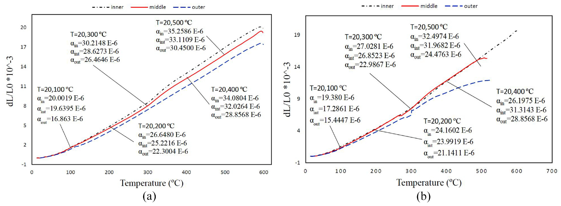
Dilatometry curves obtained by the dilatometer machine: (a) sample 3 and (b) sample 4.
As shown in Figure 13(b), the difference between the thermal expansion coefficient in the inner layer and the outer layer was very high, which can be attributed to the higher percentage of reinforcing particles in the outer layers due to the vibration. Due to a significant difference in the thermal expansion coefficients of SiC and aluminium alloy 413.1, the difference of these parameters in different layers was more evident than for a pure alloy (22.04 K−1 in 20, 100°C). Thermal expansion is not always a linear function. This means that the coefficient of thermal expansion is not always constant. As shown in Figure 13(b), there was an unusual thermal expansion event in sample four between 260°C and 300°C. This unusual thermal expansion can be attributed to dislocations in sample No. 4. The locations where dislocation recovery occurs can experience different expansion/contractions than locations where normal expansion/contraction occurs. 44 However, for sample four, the expansion and contraction followed a non-linear trend.
Porosity
From the microstructure analysis, the regions with porosity were also identified. The types of porosity observed were: (a) porosity associated with individual particles, (b) porosity associated with the SiC particle clusters, (c) microporosity in the matrix metal, and (d) gas porosity. 45 These regions with porosity were well visualised by the secondary electrons during SEM (secondary electrons are beneficial for the inspection of the topography of the surface of a sample) (Figure 14). The porosity associated with individual particles can occur due to humidity on the particles or shrinkage cracks. Figure 14(b) shows that the presence of air among clustered particles could also be seen in this sample. It seems that the use of the mechanical stirring method under these conditions could not prevent the formation of agglomerated particles at 750°C. At higher stirring speeds, the porosity observed in the microstructure increased; the main reason for this is the presence oxide skins, gases and contaminants due to vortex formation. 46 It seems that gas entrapment occurred mainly at the lower annular speed and without vibration. As mentioned earlier, during the fabrication of vibrating parts (Figure 7), the migration of gas bubbles to the inner radius occurred more rapidly, and the percentage of porosity in these parts was much more limited.
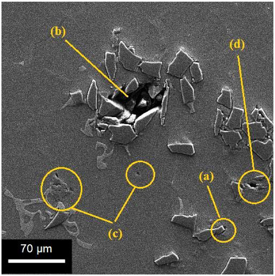
Micrograph from SEM secondary electrons of pores in FGM: (a) porosity associated with an individual particle, (b) porosity associated with SiC particle clusters, (c) microporosity in the matrix metal and (d) gas pores.
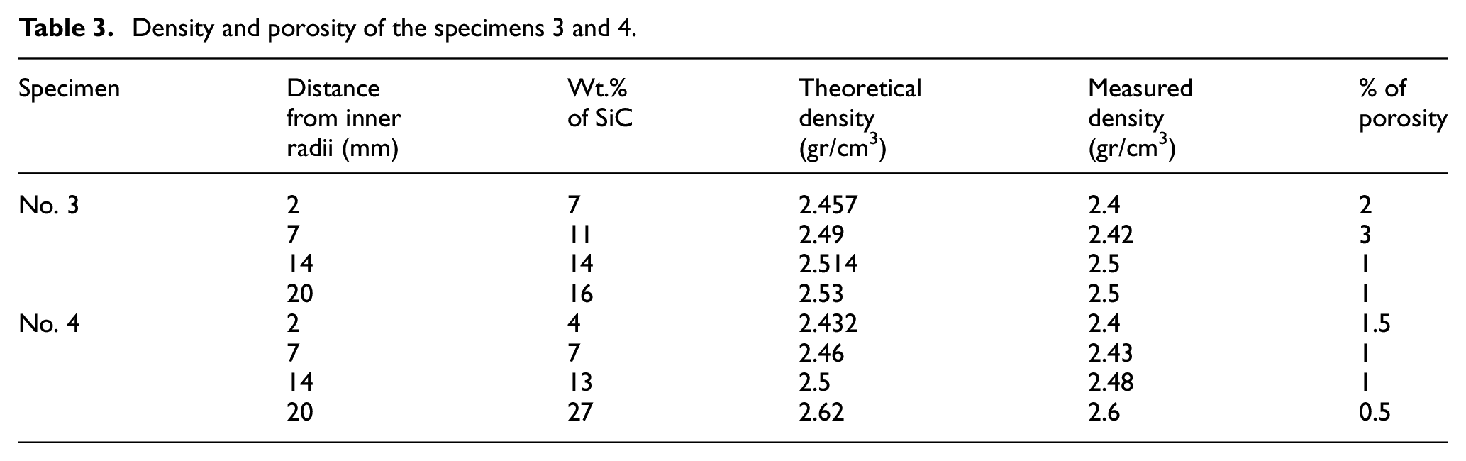
A quantitative assessment of SiC particles in the FGM samples was performed using the chemical dissolution method. 47 This included weighing the sample, dissolving it in 2 mol/L hydrochloric acid, filtering the suspension, drying the SiC particles and determining the weight percentage of SiC. 48 By comparing the theoretical and practical densities, the percentage of pores was obtained.
Due to the risk of working with strong acids, the percentage of particles and pores was determined only for specimens 3 and 4. The percentage of reinforcing particles and pores were calculated and are given in Table 3. As mentioned earlier, the percentage of pores in specimen four that used vibration was lower. The data had an error tolerance ±0.2.
Density and porosity of the specimens 3 and 4.
Conclusions
To investigate the properties of FGM materials better and more accurately, the design, fabrication and analysis of FGMs by CSPM and VCSPM were carried out herein. This work is the first report of a novel fabrication method for FGMs with the application of the centrifugal force. The benefits of vibration in traditional castings supported the study of functionally graded materials by the centrifugal casting method. Initially, a centrifugal casting machine equipped with a furnace and control of the mould speed, temperature and melt temperature was designed and manufactured to make FGM parts. Then, the centrifugal casting method with powder particles and a vibration was invented and presented to provide a practical and faster method for grading the reinforcing particles. A comparison of sample properties and particle grading rates for conventional and innovative methods was performed. In general, the results indicated an increase in the slope of the graph of changes for samples made by VCSPM. The base metal was aluminium A413.1, and silicon carbide reinforcing particles were considered. The primary outcomes of this research are as follows:
As evident from the results, a vibration, especially at low and medium rotational speeds, improved the quality of the FGM components. The most important reason is an increase in the migration speed of air bubbles and impurities to the inner layer and reinforcing particles to the outer layer. At high speeds and in the presence of a vibration, the extensive formation of SiC particle clusters, shrinkage and porosity at the interface significantly reduced the strength of the FGM, even though it had more incorporated ceramic particles.
From the obtained microscopic images, it can be seen that with increasing rotational speed, the volume fraction of particles in the outer radius increased; the intensity of this increase was much higher when using the VCSPM process. It was observed that vibration dramatically increased the rate and speed of migration of gas bubbles towards the inner radius.
The density also increased when moving from the inner radius to the outer radius of the FGM cylinder. The porosity associated with the particle clustering and the matrix reduced the density of the FGMs.
It can be concluded that in the FGM cylinders, the mechanical properties (hardness, YS, UTS and E) improved when moving from the inner to the outer radii due to an increase in the percentage of silicon carbide particles. When the velocity increased and vibration was used, the slope of these changes increased.
The coefficient of thermal expansion also decreased with increasing silicon carbide particles in the base metal. This decrease can be attributed to the lower thermal expansion coefficient of silicon carbide particles compared to that of aluminium.
With an increase in the number of SiC particles in the outer layers due to the lower coefficient of thermal expansion for the matrix SiC particles than that of aluminium, the coefficient of thermal expansion also decreased.
An investigation of the inner radius of the cast cylinders indicated the presence of gas pores and a few agglomerate particles. The centrifugal force drove the gas bubbles in the melt to the inner radius of the cast cylinders because of their lower density. It is evident that these effects were exacerbated with the use of a vibration, and the quality of the produced parts increased.
The limitations of the VCSPM method are the control of the production parameters, particle clustering and creation of pores in the final part. Future work can investigate the effect of vibration parameters on the distribution of particles in vacuum castings to reduce porosity.
Footnotes
Declaration of conflicting interests
The author(s) declared no potential conflicts of interest with respect to the research, authorship, and/or publication of this article.
Funding
The author(s) received no financial support for the research, authorship, and/or publication of this article.