
Abstract
The straightness of seamless welded rail (SWR) is very important for high speed railways. To improve the straightness of SWR, in this paper, we propose a three-point bending straightening algorithm for I-type SWR. It has been verified by theoretical analysis, finite element simulation, and experiments. The three-point bending straightening algorithm for I-type SWR has three steps: (1) three-point bending straightening prediction models are established based on simplified cross-section; (2) shape compensation coefficients are proposed to reduce the influence of simplified cross-section on the accuracy of the prediction models; (3) effective simplified cross-section dimensions are determined by optimizing shape coefficients with the Trust-Region-Reflective Least Squares method. The three-point bending straightening algorithm, which meets the needs of prediction precision in the industrial application, is stable and convergent, and could be the basis of further intelligent straightening.
Keywords
Introduction
High speed railways require SWRs to have high levels of straightness for its long term stable and safe operation. The production process of SWRs mainly includes five stages: rolling, cooling, roller straightening, welding, and three-point bending straightening. Usually the steel factory provides straight 100-m rails without seams through the rolling and cooling process, and guarantee their straightness by roller straightening.1,2 The straight rails are then welded to 500-m SWRs in the welding factory. Afterward the SWRs are straightened by three-point bending process, and protruding areas near weld joints are removed for transporting to track installation sites.
Even though there are many studies and works on straightening, the available research references mainly focused on two aspects. The first aspect is roller straightening for rolled rails without seam. Because the roller straightening process needs large strokes, complex residual stress remains in the SWRs3,4. Liu et al. 5 found that the distribution curve of residual stress in the vertical direction of the heavy rail was approximately C-shape after roller straightening. Biempica et al. 6 reduced the residual stress by improving finite element model with contact conditions between the rails, the rollers, and the kinematic hardening material model. Finite element and orthogonal calculation 7 can also reduce the residual stress of straightened rails. Pernía et al. 8 combined finite element method and genetic algorithm to determine the best roller position to ensure the minimum residual stress following roller straightening.
The other aspect is the three-point bending straightening for shaped shafts and guide rails without seam. 9 Because of the importance of prediction of spring-back, loading force, and straightening load, Lu et al. 10 adopted a stroke-deflection model that focuses on the straightening stroke prediction for linear guide rails by contrasting and integrating the bending experimental results and finite element simulation data. Hong and Xiong 11 proposed the straightening process control model for shaft parts which combined the straightening stroke method based on iteration and straightening stroke algorithm based on empirical data. Pei et al. 12 established a straightening prediction model for both side-cut and flat-cut D-type cross section shafts by using the classic principle of material mechanics and curvature conversion methods to provide an accurate and practical relation between the straightening press curvature and the initial bending curvature, whose prediction accuracy was highly dependent on the measurement accuracy. At the same time, material parameters13,14 of the guide rail had an important influence on the prediction of spring-back. Song and Yu 15 gave analytical formulas for the spring-back of T-section rail and residual curvatures based on linear-hardening model and elastic-plastic power-exponent hardening model of the material. Elastoplastic mechanics and ideal elastic-plastic material model 16 were also adopted to establish the relationship between the initial deflection of the round bar and the straightening stroke. Thipprakmas and Sontamino 17 investigated the influences of the coined-bead die on the spring-back characteristics during V-die bending for aluminum alloy sheets (AA1100-O) by using the finite element method and related physical experiments. Gao et al. 18 investigated the spring-back behaviors of the AA6082 aluminum profiles based on the flexible multi-points 3D stretch-bending process to achieve high-efficiency and high-quality forming of such kind of structural components. Song 19 combined the power exponential hardening model of the material and the simple unloading law to determine the analytical formula of the relationship between the initial deformation of the T-section rails in the pressure straightening (means straightening by controlling loading force or pressure) process, straightening load, and loading deflection. There were many references20–23 combining neural networks and finite elements to establish the spring-back prediction model of the workpiece after bending.
In summary, there were few literatures about three-point bending straightening algorithm for I-type SWR and its applications. Next, the bending and spring-back of SWR was simulated according to actual straightening conditions, whose results indicated that the straightening of SWR can be substituted by short straight rails with the same loading force and fulcrum conditions. To simplify the prediction calculation, the cross-sectional shape of the SWR can be reduced to seven dimensions to build up the straightening prediction model. Then the shape compensation coefficients were proposed to improve prediction precision of the model. Finally, the three-point bending straightening algorithm was tested and verified in industry applications.
Three-point bending straightening process for SWR
Straightening area of SWR
Figure 1 shows SWR straightness deviation measured by straightening machine SKJ-2500. The reference line is the upper contour of rail without welding joint, whose precision is guaranteed by rolling mills. After welding, there appears a protruding area, which is called straightening area here. The objective of straightening is to put the upper contour of SWR within straightening area into permissible range of straightness deviation. In the straightening area, there is a milling area, which includes weld joint as shown as the dotted line in Figure 1. The straightness deviation of milling area could be beyond the upper range, but it will be removed after straightening process. The length of the measuring area is determined by straightening machine, the longer the better. The length of SKJ-2500 is about 1200 mm.
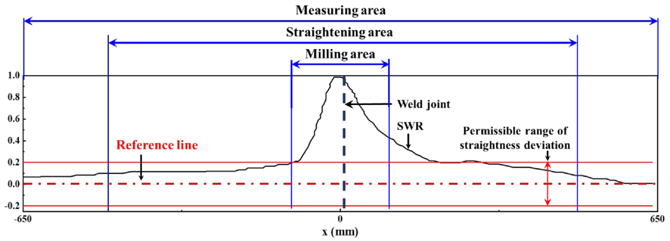
Straightening area of SWR.
Three-point bending straightening process for SWR
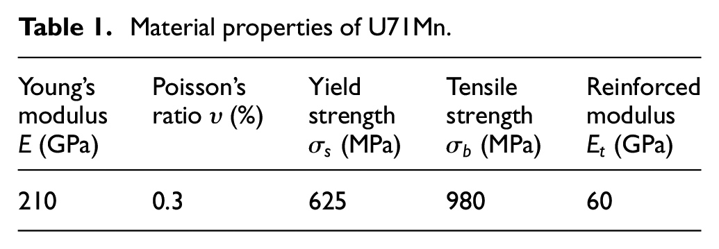
Material properties of U71Mn, for high speed railway, were obtained by experiments and shown in Table 1. Sample of U71Mn was tested in tensile testing machine. The curve of stress-strain of U71Mn was obtained near plastic yield point as shown in Figure 1. For convenience, the material is treated as linear hardening beyond plastic yield. The reinforced modulus
Material properties of U71Mn.
The straightening process of SWR under loading force 1365 kN and fulcrum distance 1000 m was analyzed by FEM. General purpose FEA software Abaqus was employed for the numerical simulations. A FE model of SWR with 5000 mm length was used to present the straightening process as shown in Figure 2(b). The 5000 mm length SWR consisted of 71,500 C3D8R elements with approximate global size of 10 mm. Gravity load 9.8 m/s had to be applied for its large compliance along axial direction. A small friction coefficient 0.1 was set to all contact surfaces between fixed supports, fulcrums, indenter, and the SWR. Fixed supports and fulcrums were constrained at all freedom degree. Displacement load was applied to the indenter at two steps: loading to straightening, unloading to spring-back. Abaqus/Standard module was adopted to solve the quasi-static analysis, and results are shown in Figure 3. The shading regions in Figure 3(a) and (c) have the same thickness along dotted line and need to be removed after straightening.
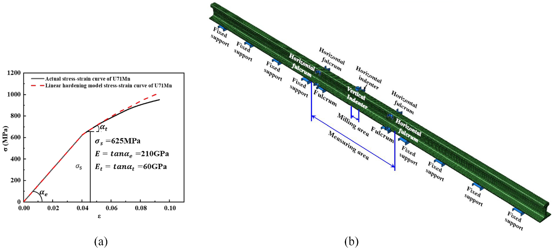
FE model of SWR straightening process: (a) stress-strain curve of U71Mn and (b) FE model of SWR straightening process.
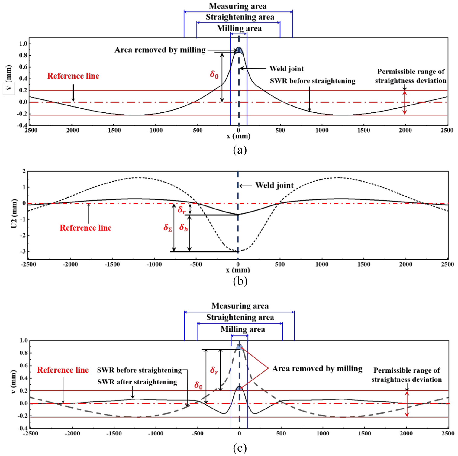
The straightening process for SWR: (a) straightness deviation of SWR: before straightening, (b) retained deflection of SWR, and (c) straightness deviation of SWR: after straightening.
Three-point bending straightening prediction model for SWR
Another FE model of SWR with 1200 mm length was used to focus on the straightness deviation in the measuring area. This 1200 mm length SWR consisted of 92,160 C3D8R elements with approximate global size of 5 mm. All boundary, load conditions, and solution method were the same as those of the long model. If the SWR after straightening without the area removed by milling, as shown in Figure 3(c), is regarded as ideal straight rail (ISR), the SWR before straightening can be represented as the model in Figure 4(a). Using the prediction model for analysis, the model in Figure 4(a) can be replaced by an ISR as initial state in Figure 4(b). The retained deflection
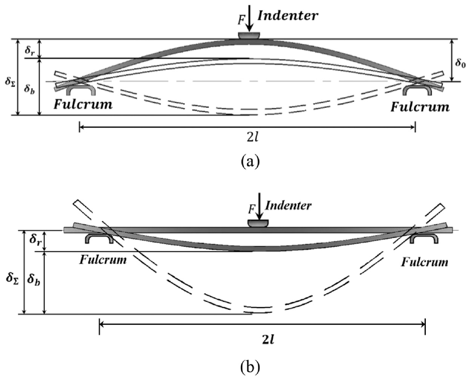
Diagram of three-point bending straightening (a) process for SWR without area removed by milling and (b) prediction model based on initial straight rail.
The SWR outside the measuring area is quite straight after straightening as shown in Figure 3, so the focus is actually within the measuring area. Then the question becomes whether boundary conditions could affect the elastic-plastic response of the rail or not. The deformation of ISR with 1200 mm length, namely the measuring area, was analyzed by the loading force 1365 kN, the same as the SWR straightening loading force in Figure 3. Its retained deflection is shown in Figure 5.
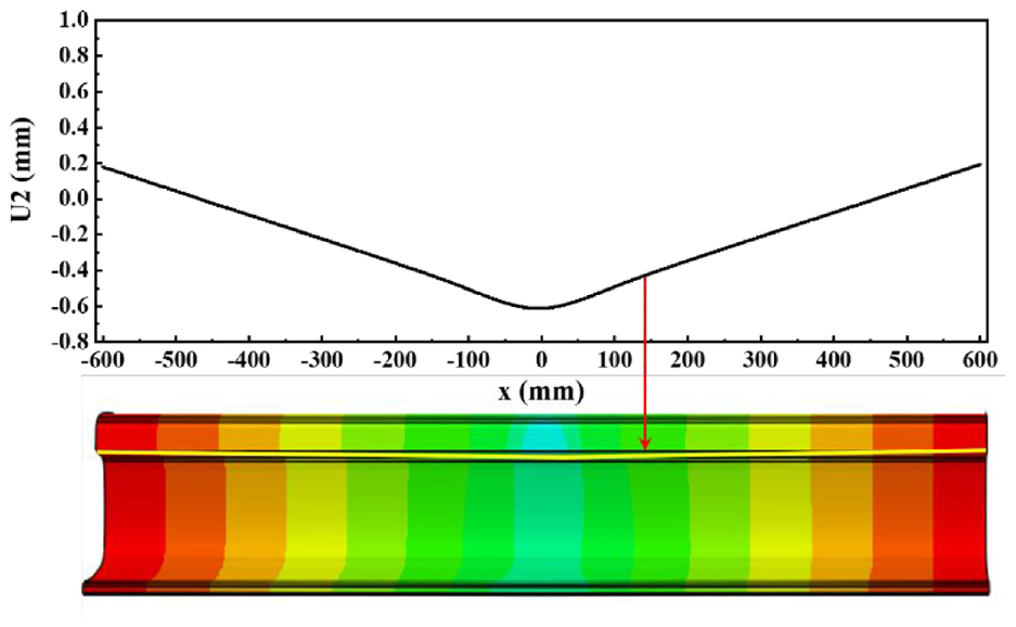
The retained deflection of 1.2-m ISR within measuring area.
The comparison of retained deflections with same loading force, between 5-m SWR and 1.2-m ISR, is shown in Figure 6. The maximum difference is 0.048 mm and appeared at about 450 mm from the weld joint. These results indicate that the ISR with measuring area could be used to predict the SWR deflection near weld joint.
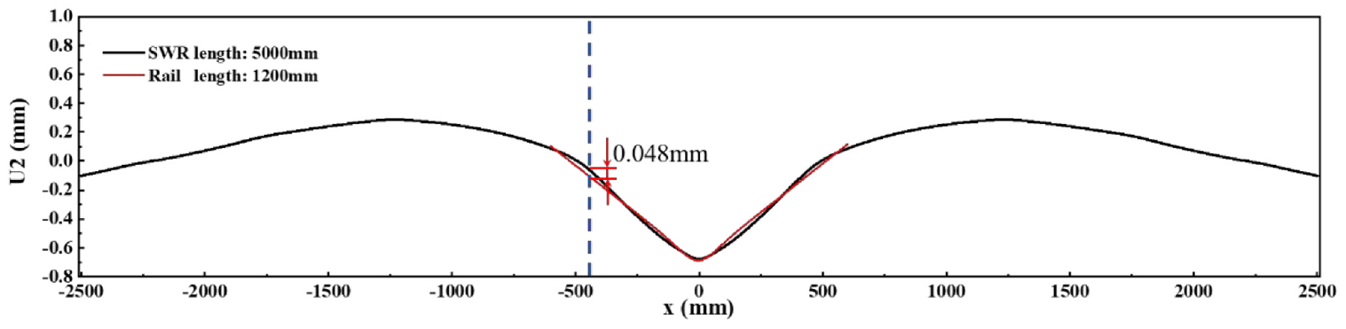
Comparison of retained deflections between the SWR with 5 m length and the ISR within measuring area.
Three-point bending straightening prediction models based on simplified cross-section
Simplified cross-section of SWR
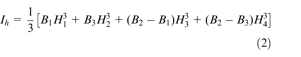
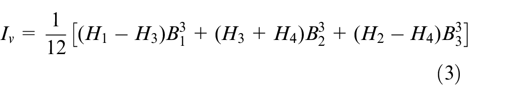
As shown in Figure 7(a), the SWR has an I-type cross-sectional shape, and it can be divided into rail head, rail waist, and rail bottom from top to bottom. To simplify the prediction calculation, the cross-sectional shape of the SWR can be reduced to seven dimensions,
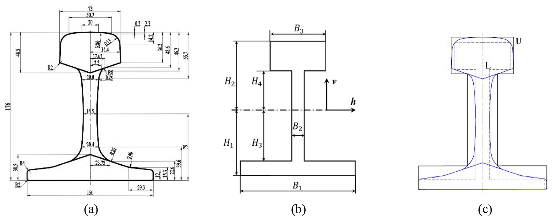
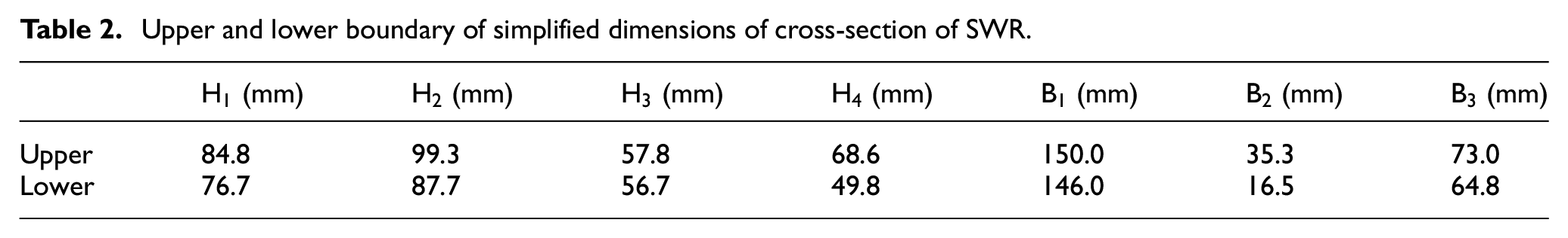
Simplification of SWR cross-section: (a) SWR cross-section, (b) simplified cross-section, and (c) the range of simplified cross-sectional dimensions of SWR.
Upper and lower boundary of simplified dimensions of cross-section of SWR.
Next, the three-point bending straightening prediction models are established based on a simplified cross-section and four straightening conditions.
Three-point bending straightening prediction model of simplified cross-section
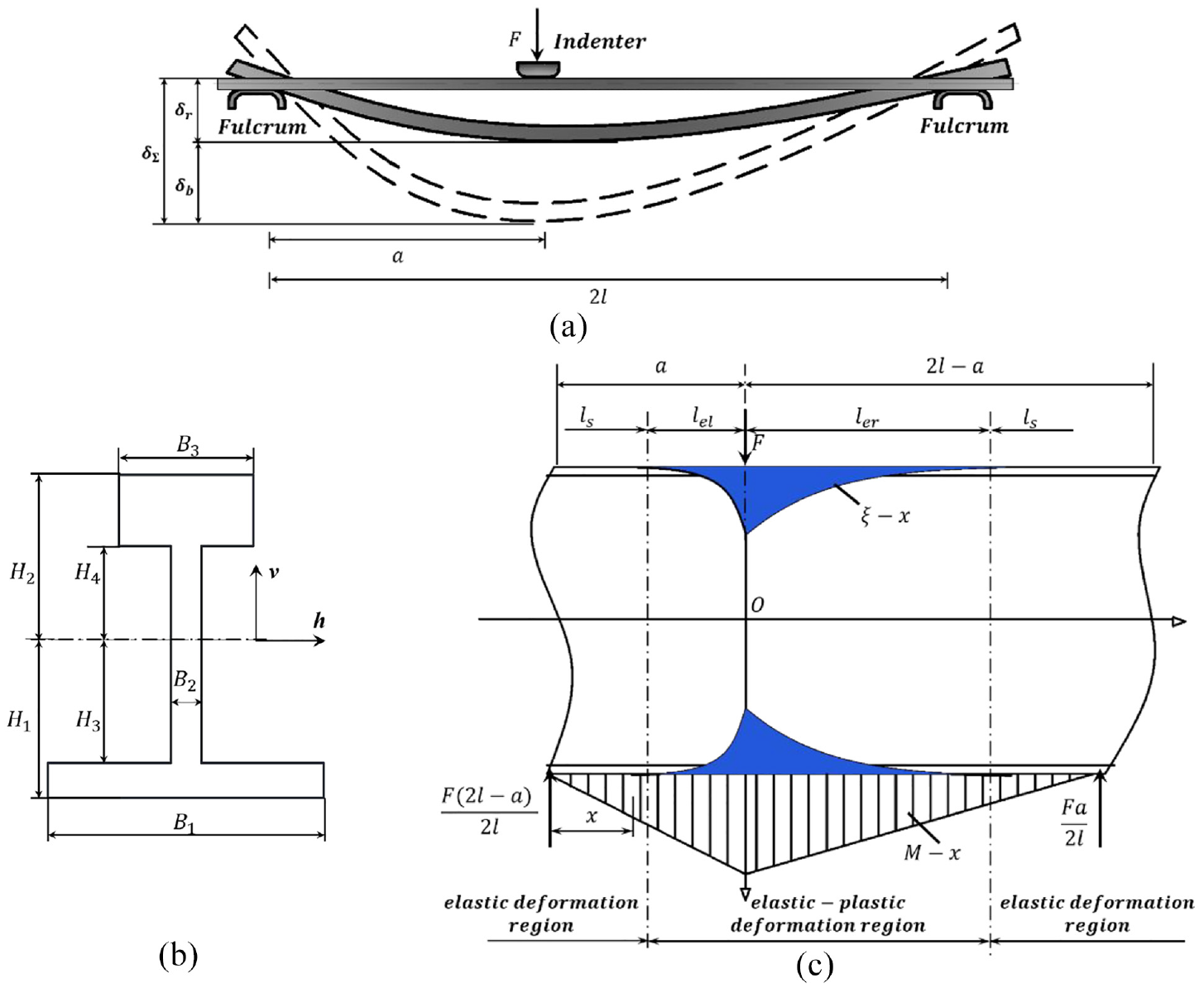
There are basically four straightening conditions of the three-point bending straightening for the SWR according to the loading direction of indenter and the distribution state of fulcrums: (1) The indenter loading vertically and the fulcrums distributed symmetrically on both sides of the indenter (VS), (2) the indenter loading horizontally and the fulcrums distributed symmetrically on both sides of the indenter (HS), (3) the indenter loading vertically and the fulcrums distributed asymmetrically on both sides of the indenter (VA), (4) the indenter loading horizontally and the fulcrums distributed asymmetrically on both sides of the indenter (HA).
Straightening condition 1: VS
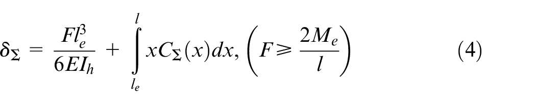
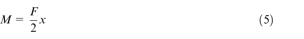
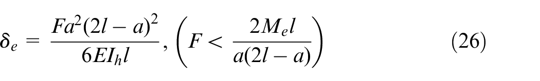
The deformation of the SWR during the straightening process can be divided into three stages: elastic deformation, elastoplastic deformation, and elastic unloading. The relationship between the loading force
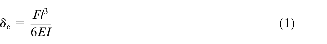
where E is the elastic modulus of the SWR material,
There are both elastic and plastic deformation regions in the SWR with elastoplastic deformation, as shown in Figure 8(b), where 2
where
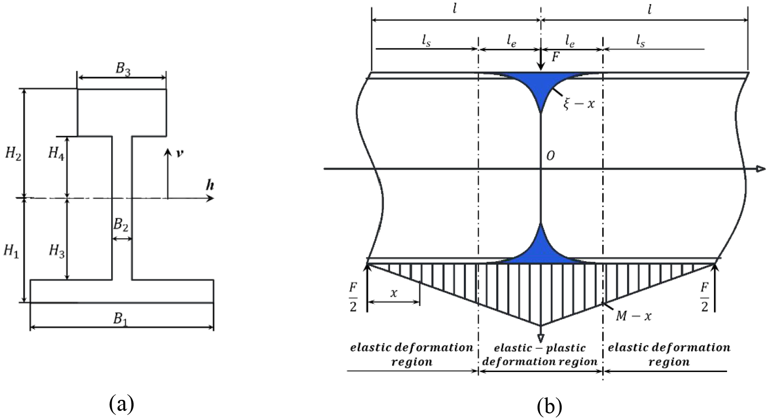
Elastic-plastic region and bending moment diagram for VS and HS condition, (a) simplified cross-section, (b) elastic-plastic region and bending moment diagram in longitudinal section.
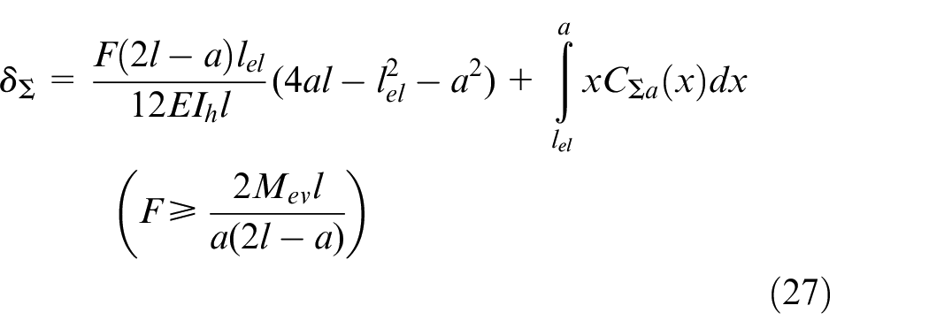
Because of the difficulty of explicit expression of
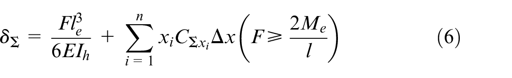
where the numerical integration interval
In unloading process based on elastic unloading criterion, the relationship between springback
The amount of residual deformation is
A linear hardening material model as shown in Figure 9(c) is adopted to describe the stress distribution along vertical direction in cross-section as shown in Figure 9(b).
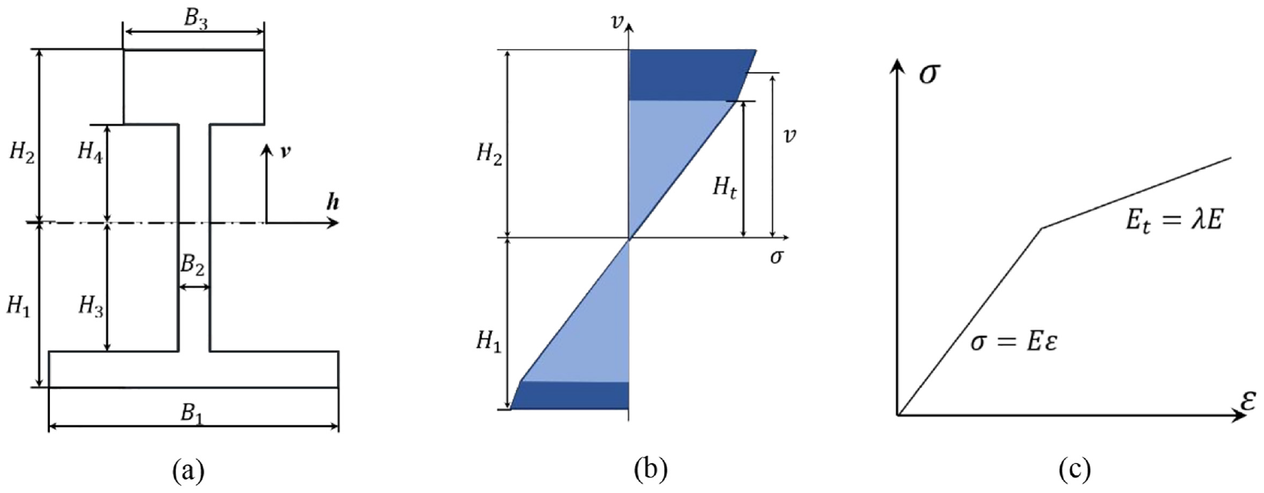
Stress distribution of SWR cross-section at loading point for VS condition: (a) simplified cross-section, (b) stress distribution along vertical direction in cross-section, and (c) linear hardening material model.
The hardening model of the SWR material can be formulated as:
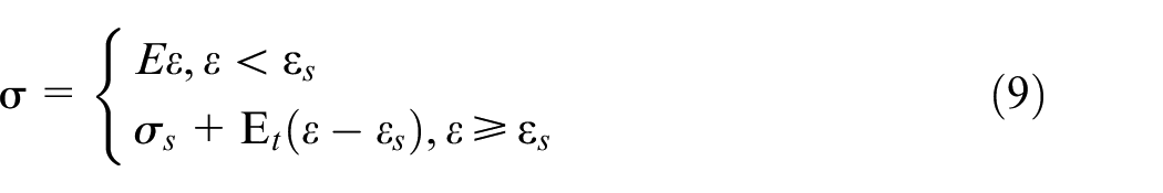
where
Combined with the simplified SWR cross-sectional shape, equation (9) can be expressed as,
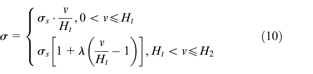
where
The elastic limit bending moment
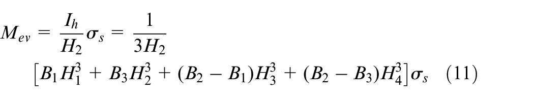
During the straightening process beyond elastic limit, the plastic region of the SWR cross-section will increase as the loading force increases. There are three stages in the process of loading beyond the elastic limit which can be expressed by
(1) stage one:
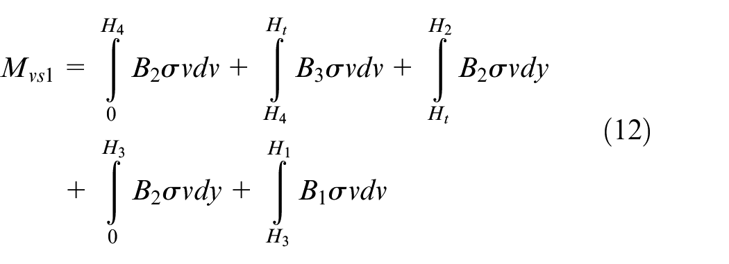
Then the bending moment ratio of the stage one is obtained as:
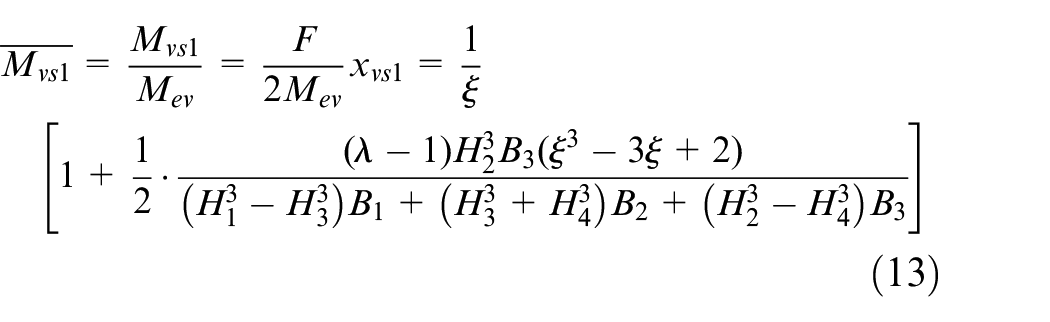
According to the analysis of the curvature of each stage in the straightening process, it can be obtained as:
where
(2) stage two:
Then the
(3) stage three:
The

Considering equations (8) and (20), straightening prediction model of VS condition can be expressed as:
Distribution of elastic-plastic region of SWR cross-section, including three stages: (a)
Straightening condition 2: HS
The elastic limit bending moment
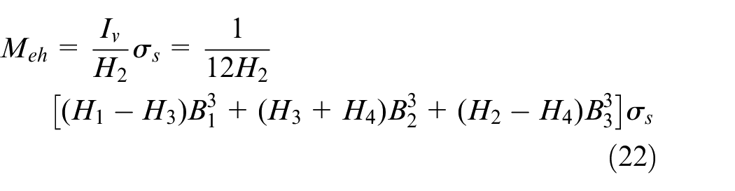
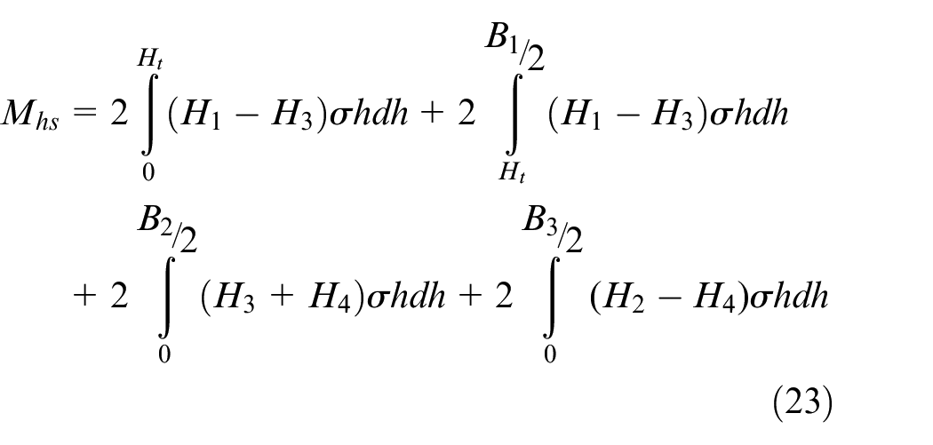
In actual straightening process, the horizontal loading never causes plastic deformation of the rail head. Therefore, there is only one stage in loading beyond elastic limit, where the rail bottom experiences plastic deformation for the horizontal straightening as shown in Figure 11(a).
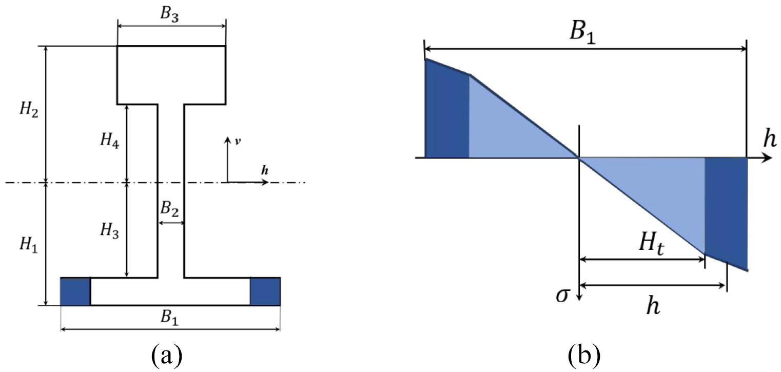
Stress distribution of SWR cross-section at loading point for HS condition: (a) elastic-plastic region distribution of SWR cross-section and (b) stress distribution along horizon direction in cross-section.
According to the analysis of Figure 11(b), the bending moment
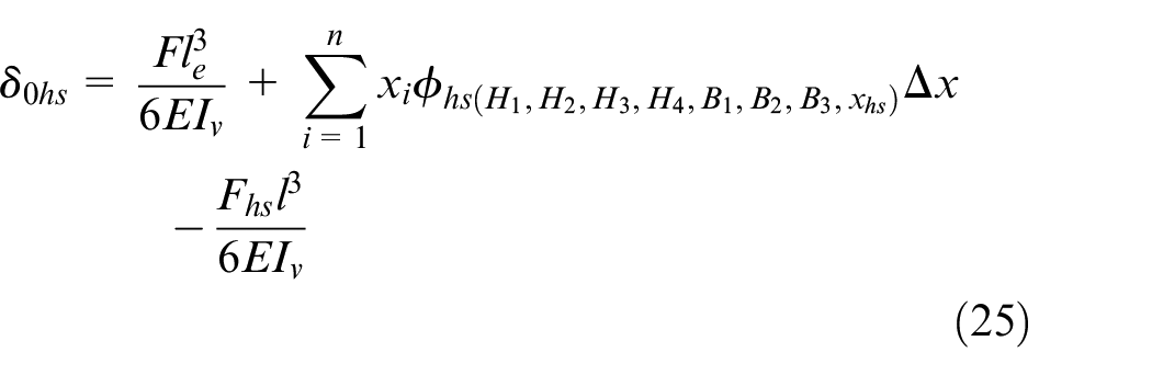
The
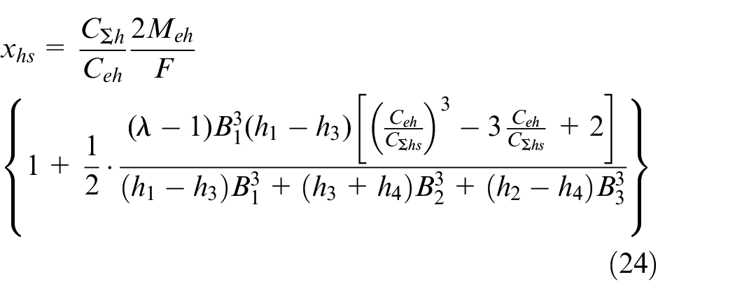
Considering equations (8) and (24), straightening prediction model of HS condition can be expressed as:
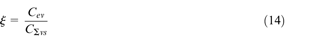
Straightening condition 3: VA
Different from condition VS, the fulcrums are distributed asymmetrically on both sides of the indenter, as shown in Figure 12(a). The relationship between the loading force
where
Straightening prediction model for VA and HA condition (a) diagram of three-point bending straightening prediction model for VA and HA condition (b) simplified cross-section of SWR, and (c) elastic-plastic region and bending moment diagram for VA and HA condition.
There are both elastic and plastic deformation regions in the SWR with elastoplastic deformation, as shown in Figure 12(c), where
where
According to the bending moment diagram
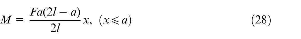
The approximate solution of the SWR straightening stroke under the straightening condition VA is formulated as by numerical integration,
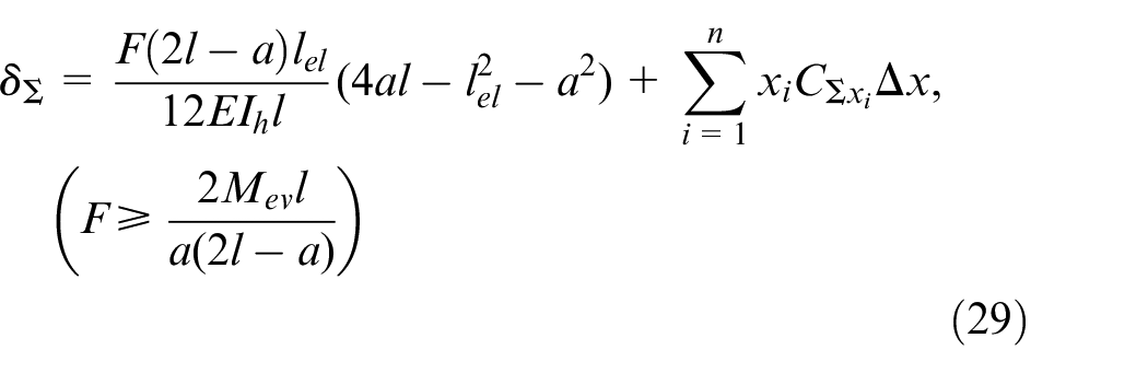
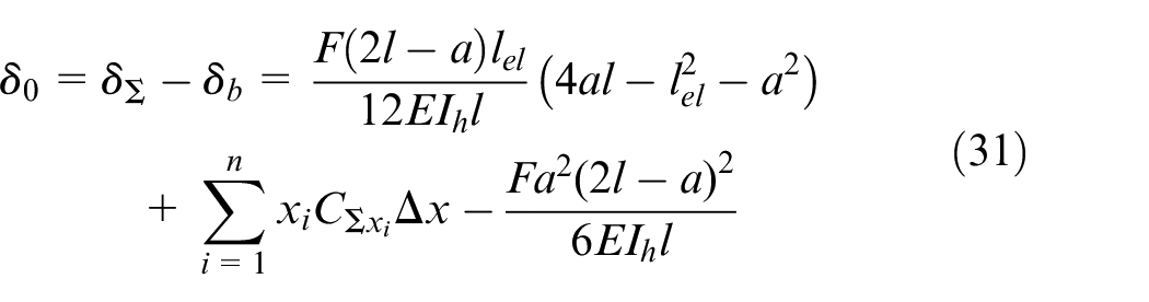
In unloading process based on elastic unloading criterion, the relationship between springback
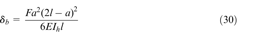
The amount of residual deformation is
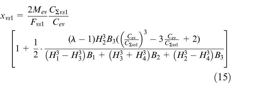
There are also three stages in loading beyond elastic limit as the same as the condition VS.
(1) stage one:
Then the bending moment ratio of the stage one is obtained as:
Therefore, the
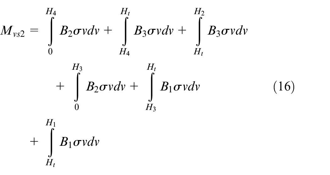
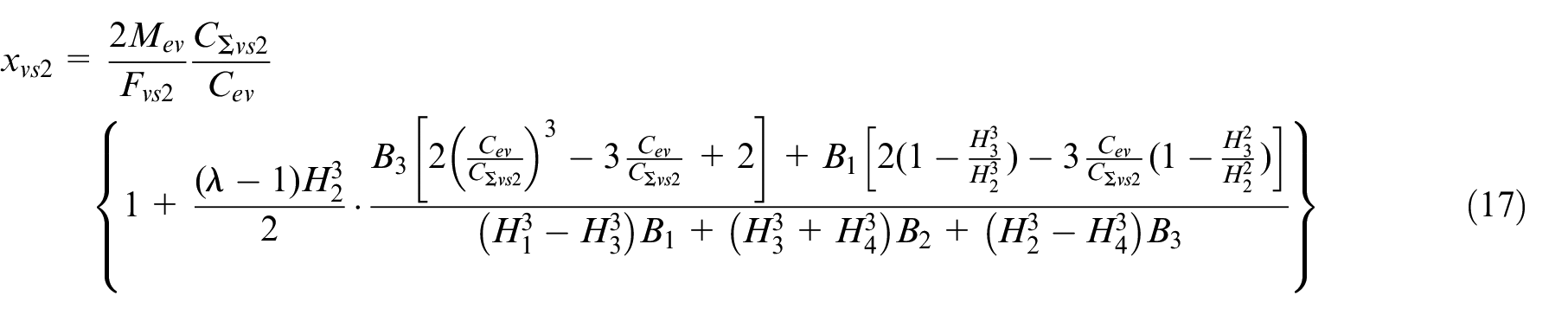
(2) stage two:
Then the
(3) stage three:
The

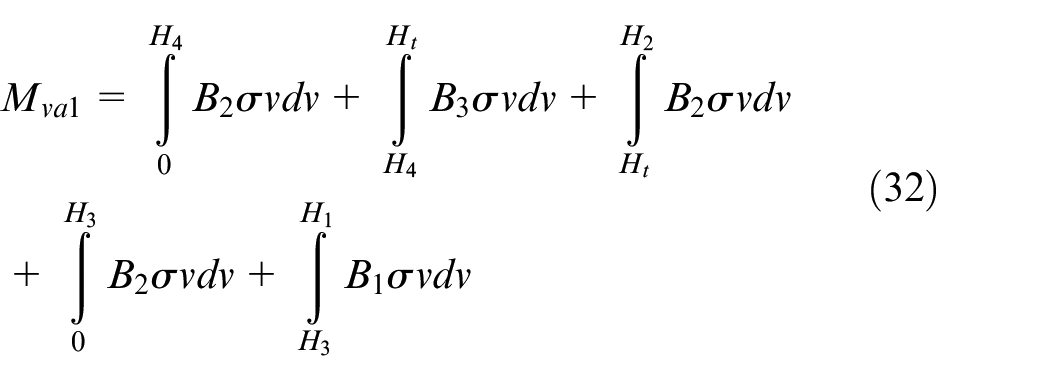
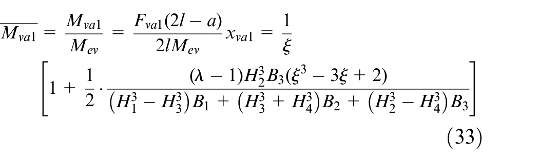
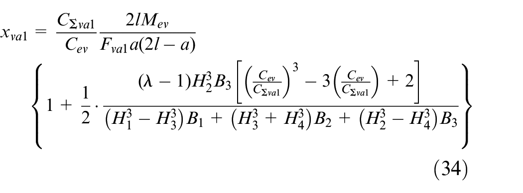
Considering equations (31) and (39), straightening prediction model of VA condition can be expressed as:
Straightening condition 4: HA
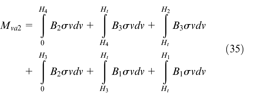
According to the analysis of Figure 12(c), the bending moment

The
The

Considering equations (31) and (43), straightening prediction model of HA condition can be expressed as,
Straightening prediction models with shape compensation coefficient
Straightening prediction models with the shape compensation coefficients are proposed for the four straightening conditions.
Finite element modeling
According to the straightening conditions in the actual straightening process, this paper establishes a finite element analysis model of the SWR, which is the same as the short model mentioned in Section 3.2. As shown in Figure 13, the entire straightening system in the finite element model includes the SWR, the left and right fulcrums, the indenter for vertical straightening, the horizontal fulcrums, and the horizontal indenter for horizontal straightening. Presented is the analysis of the straightness deviation of the SWR after pressure straightening, and the finite element data of the straightening process parameters obtained by the finite element method.
The FEM models: (a) the fulcrums are symmetrically distributed on both sides of the indenter and (b) the fulcrums are asymmetrically distributed on both sides of the indenter.
Shape compensation coefficients for simplified cross-section
Shape compensation coefficients are proposed to reduce the influence of simplified cross-section on accuracy of prediction models. Reasonably, the range of simplified cross-section dimensions of SWR, as shown in Figure 7(c), is used to determine the upper and lower boundary of simplified cross-section. Then the shape compensation coefficients are defined as below,
where
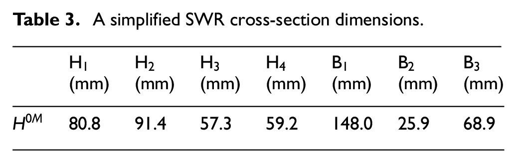
Therefore, the reference simplified cross-section dimensions
A simplified SWR cross-section dimensions.
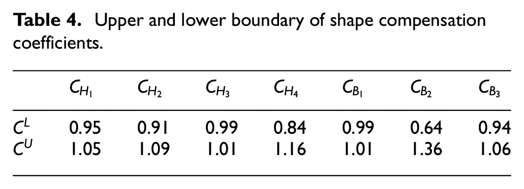
The upper and lower boundary of the corresponding shape compensation coefficients
Upper and lower boundary of shape compensation coefficients.
Determine the effective simplified cross-section dimensions
Below is the procedure to determine the effective simplified cross-section dimensions.
Calculate loading force
Set reference simplified cross-section dimensions
Calculate
Define objective function
Define upper and lower boundary of shape compensation coefficients,
Adopt Trust-Region-Reflective Least Squares, obtain effective shape compensation coefficients
Finally, obtain effective simplified cross-section dimensions
Straightening prediction models with shape compensation coefficients
Straightening condition 1: VS
On straightening condition VS, set loading force
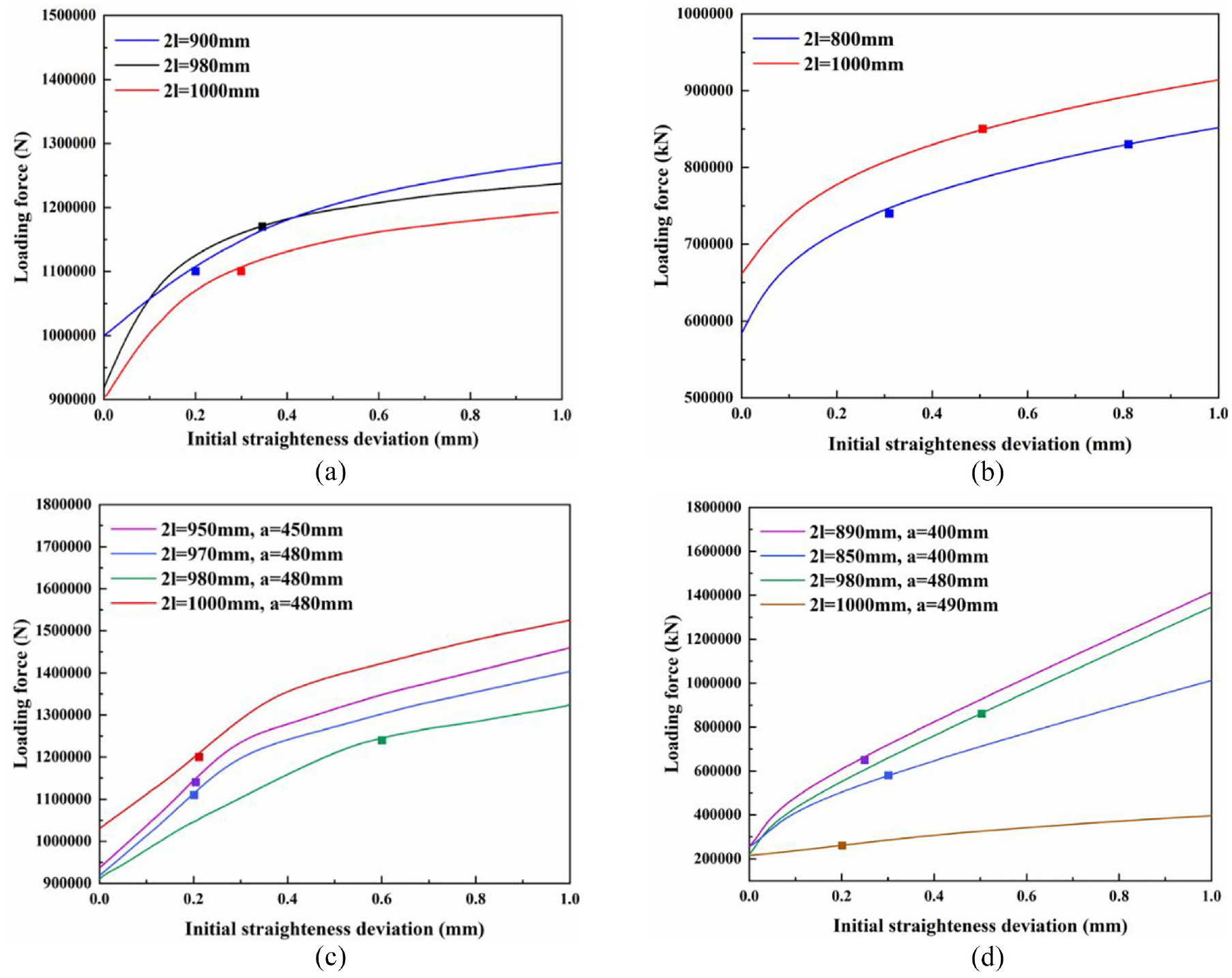
The effective simplified cross-section dimensions are applied to equation (21) to obtain straightening prediction model of VS condition, which compared to finite element simulations as shown in Figure 14(a). And the differences are lower than 0.85%.
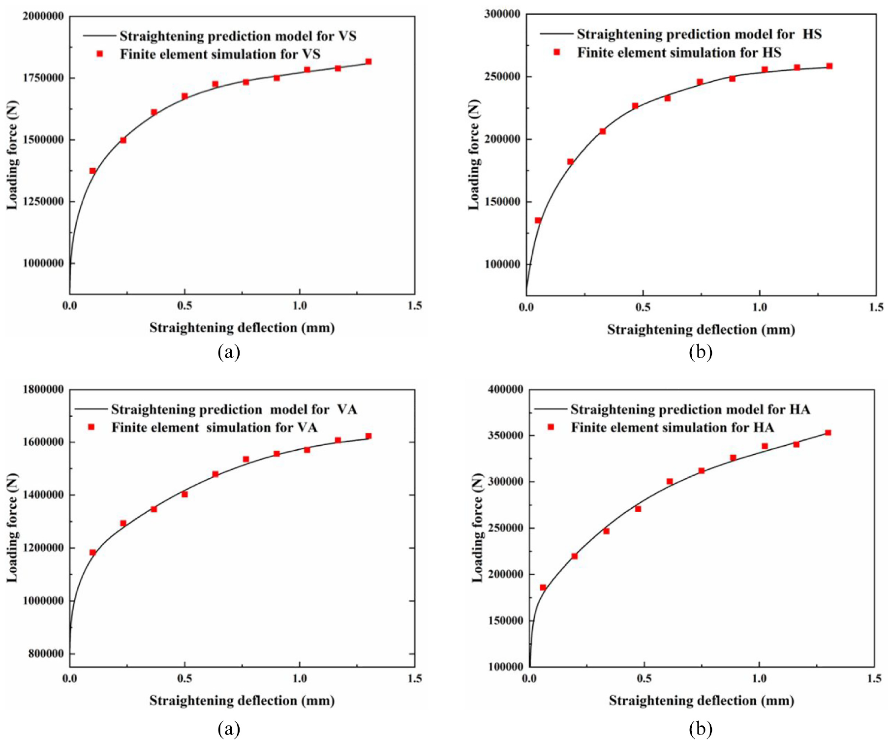
Comparison between straightening prediction models and finite element simulations for different straightening conditions: (a) VS, (b) HS, (c) VA, and (d) HA.
Straightening condition 2: HS
On straightening condition HS, set loading force
The effective simplified cross-section dimensions are applied to equation (25) to obtain the straightening prediction model of HS condition, which is compared to finite element simulations as shown in Figure 14(b). And the differences are lower than 1.21%.
Straightening condition 3: VA
On straightening condition VA, set loading force
The effective simplified cross-section dimensions are applied to equation (40) to obtain straightening prediction model of VA condition, which is compared to finite element simulations as shown in Figure 14(c). And the differences are lower than 1.07%.
Straightening condition 4: HA
On straightening condition HA, set loading force
The effective simplified cross-section dimensions are applied to equation (43) to obtain the straightening prediction model of HA condition, which is compared to finite element simulations as shown in Figure 14(d). And the differences are lower than 1.58%.
Effect of reference simplified cross-section dimensions H0
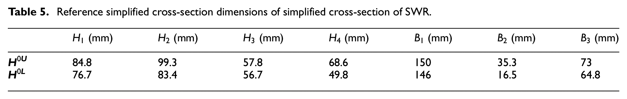
The effect of reference simplified cross-section dimensions were verified by using different reference simplified cross-section dimensions when solving shape compensation coefficients. If the effective simplified cross-section dimensions were almost unchanged under different reference simplified cross-section dimensions, the algorithm can be considered stable and convergent. To test effect of reference simplified cross-section dimensions
Reference simplified cross-section dimensions of simplified cross-section of SWR.
Change intervals of shape compensation coefficients.
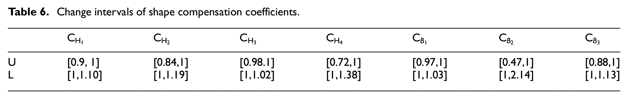
For different reference simplified cross-section dimensions
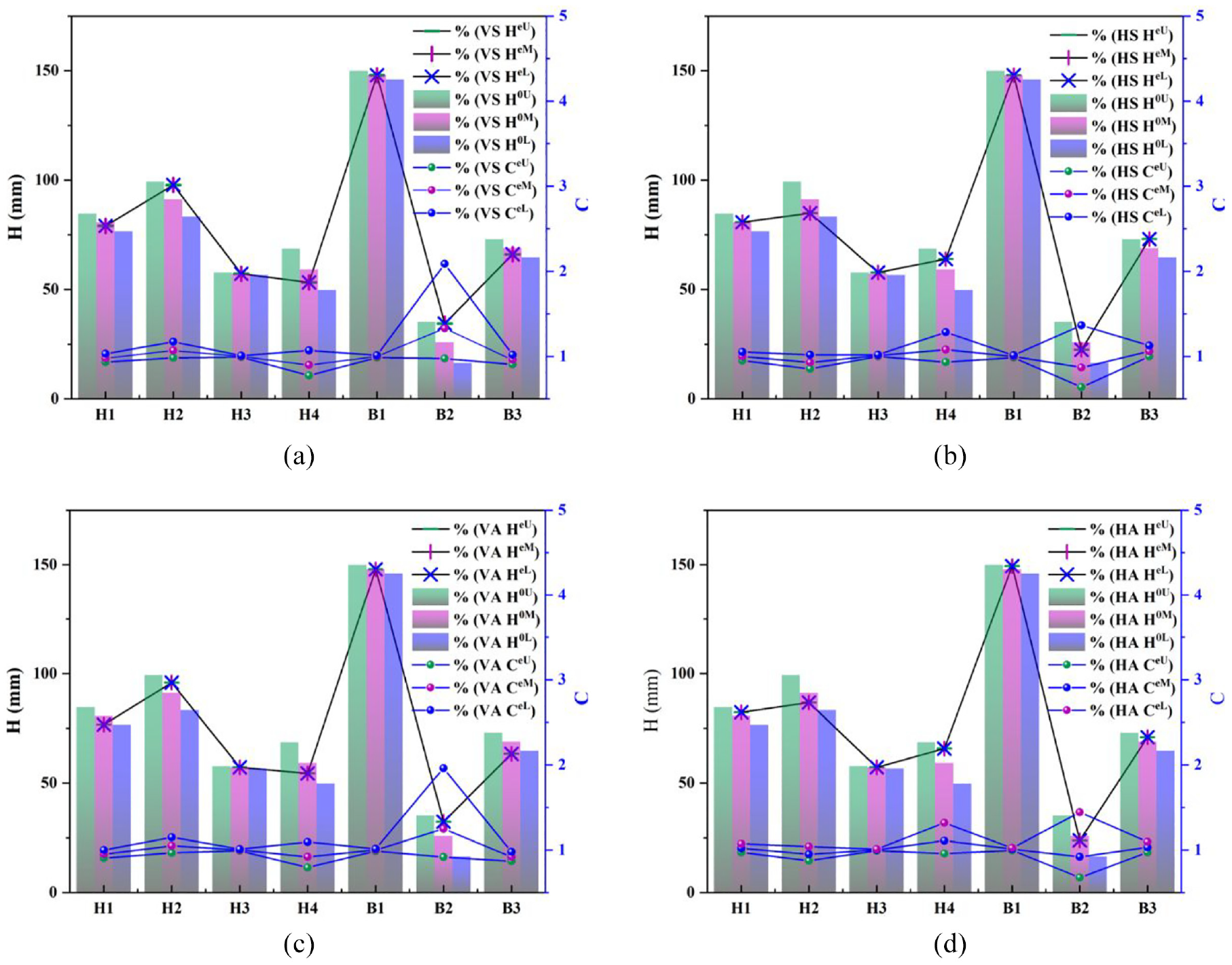
Effect of reference simplified cross-section dimensions on effective simplified cross-section dimensions for different straightening conditions: (a) VS, (b) HS, (c) VA, and (d) HA.
Verification and error analysis
SKJ-2500 straightening machine is an important link in the assembly line of SWR. The SWR is supported by fixed supports as shown in Figure 2, and moved forward. When a weld joint arrives in the SKJ-2500 straightening machine, the SWR is stopped and placed on the fixed supports freely without any other constraints. Then the height of SWR head is scanned by laser distant sensor of SKJ-2500, and the initial SWR straightness deviation
Experimental result versus predictions of straightening prediction models for different straightening conditions: (a) VS, (b) HS, (c) VA, and (d) HA.
As shown in Figure 16, 14 sets of straightening examples of the SKJ-2500 straightening machine in the working process were recorded to verify the straightening prediction models.
On straightening condition VS, set
On straightening condition HS, set
On straightening condition VA, set
On straightening condition HA, set
With the comparison of experiments and predictions, the prediction precision of the three-point bending straightening algorithm meets the needs of industrial applications.
Conclusions
Three-point bending straightening for I-type SWR on four straightening conditions was studied by theoretical analysis, finite element simulation, and experiments. The following conclusions were obtained,
The ISR with measuring area could be used to predict the SWR deflection near weld joint by comparison of retained deflections of ISR and SWR with same loading force and fulcrum conditions.
The three-point bending straightening algorithm for I-type SWR has three steps: firstly, three-point bending straightening prediction models are established based on simplified cross-section; secondly, shape compensation coefficients are proposed to reduce the influence of simplified cross-section on accuracy of prediction models; finally the effective simplified cross-section dimensions is determined by optimizing shape compensation coefficients with the Trust-Region-Reflective Least Squares method.
The effective simplified cross-section dimensions are independent of reference simplified cross-section dimensions for all four straightening conditions, which indicate that the three-point bending straightening algorithm is stable and convergent.
The accuracy of the three-point bending straightening algorithm meets the needs of industrial applications with a maximum difference of loading force lower than 1.54%.
The three-point bending straightening algorithm could be the basis of further intelligent straightening.
Footnotes
Appendix
a distance between the indenter and the closer fulcrum (mm).
E young’s modulus (GPa)
F loading force of indenter (N)
h the thickness of the plastic deformation layer of cross-section on condition indenter loading horizontally (mm)
I moment of inertia of the SWRcross-section (
2
v thickness of the plastic deformation layer of cross-section on condition indenter loading vertically(mm)
x distance from the left fulcrum (mm)
λ hardening coefficient of the SWR material
Declaration of conflicting interests
The author(s) declared no potential conflicts of interest with respect to the research, authorship, and/or publication of this article.
Funding
The author(s) disclosed receipt of the following financial support for the research, authorship, and/or publication of this article: This work was financially supported by the National Natural Science Foundation of China (No. 51975439), the authors gratefully acknowledge this support. And acknowledge Wuhan Rail Welding Base for the convenience of experiment.