
Abstract
In this paper, a Legorization method which can reconstruct LEGO model with complex internal and external structures from 3D color printing trajectory is proposed. Different from voxelization methods, by combining advanced adaptive slicing algorithm with building “high-resolution” regions with thin plates, the reconstruction accuracy of initial LEGO units can be guaranteed. Furthermore, the tree structure is employed for automatically generating support structures which can be converted into LEGO support structures. By adopting split assembly appropriately and implementing combination of these parts accurately, the reducing supporting structures can be further simplified. In order to optimize the Legorization scheme, a machine learning method is used to guarantee the quality and efficiency of the reconstruction work. Complex LEGO models are provided to demonstrate the effectiveness of the proposed method.
Introduction
LEGO bricks are popular for building creative constructions which have attracted many people all over the world. They are versatile building blocks that span a wide scope of applications, ranging from entertainment activities (e.g. LEGO Exhibition and LEGOLAND Resorts), peripheral products (e.g. the LEGO movie series), and educational tools. There are many different types of constructions, including professional LEGO sculptures and LEGO MOCs (short for My Own Creations) that rely on the player’s own imagination to create new models. Many MOC designers release their interesting works on the internet and exhibitions, as illustrated in Figure 1 (http://www.lelezhen.com/index.php?thread-57749.htm). These notable works achieve great balance between structure description and shape description: not only can the complex structures (some artists used a vertical section of the work more clearly to show the different horizons or layers) bring players exciting feelings, but the attractive appearance can give the audiences pleasant sensations, as illustrated in Figure 1(b) and (c). However, only highly experienced LEGO players can design their own diagram to build a LEGO model for their desired models.
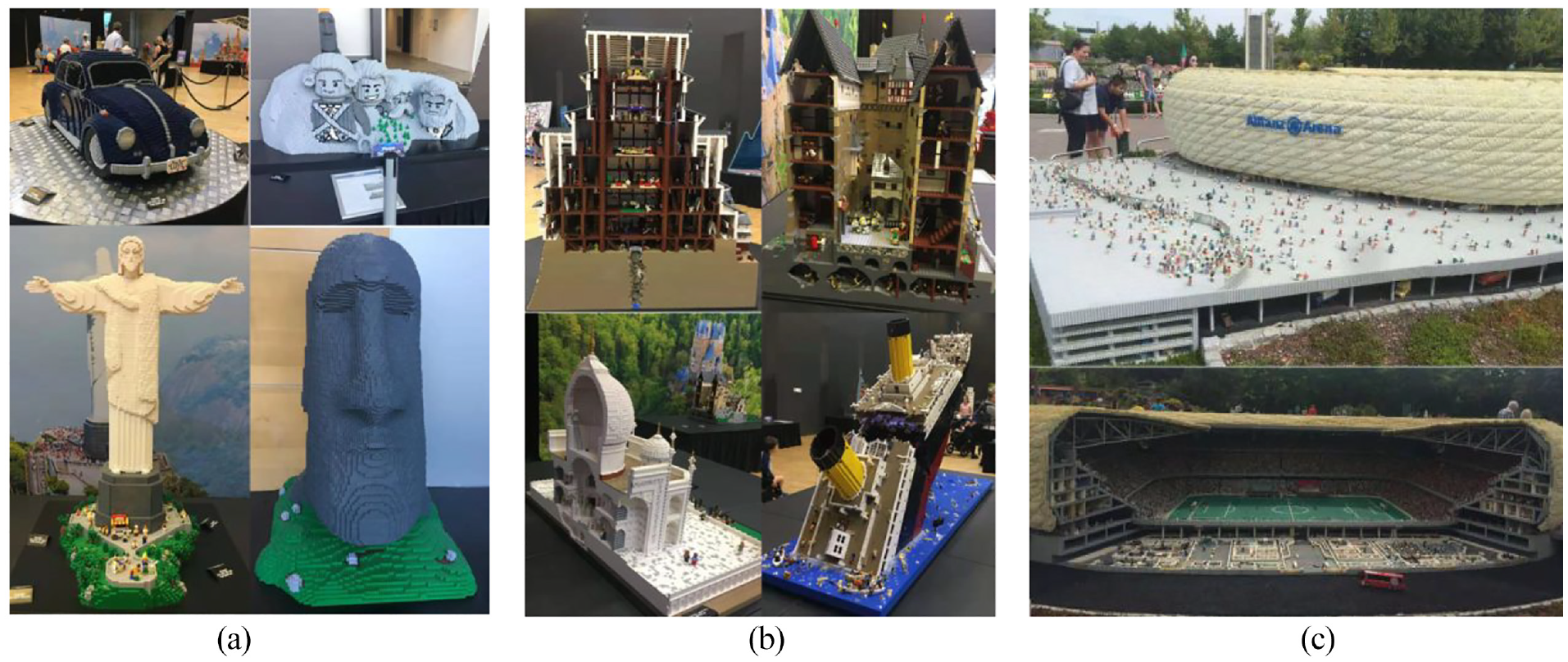
(a and b) LEGO exhibition in Brisbane Convention and Exhibition Center by Ryan McNaugh©– The Brickman – official LEGO Certified Professional (LCP). (c) LEGO Allianz Arena Sculpture located in LEGOLAND© Deutschland Resort, Germany.
Each LEGO brick has a standard size that there are at least two-direction-dimensions which are an integer multiple of 8.0 mm. On the top of bricks there are small and cylindrical bumps called studs which can hold together the brick above it, as illustrated in Figure 2(a). The Fundamental LEGO Unit (FLU) with one stud can be denoted as 1 × 1 × 1 brick with dimensions: 8.0 mm (length) × 8.0 mm (width) × 9.6 mm (height). All the LEGO series products and bricks must follow this basic principle, which can ensure the compatibility of various LEGO bricks: even bricks produced in late 1950s can be combined with bricks manufactured this year.
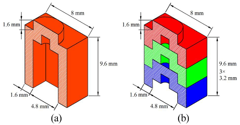
The LEGO structure of FLU and plates: (a) FLU and (b) plate.
One can also use thin sized bricks, which are very similar to LEGO bricks except that the height of thin sized bricks are one third of standard LEGO bricks (3.2 mm excluding stud height, as illustrated in Figure 2(b)). In other words, three plates can be applied for stacking to match the height of the FLU and can be utilized for building sculptures with better details.
Nowadays additive manufacturing (AM) technology is becoming more mature. More and more materials, for example, plastics, metals, and even DNA and proteins, are used to build 3D structures. Moreover, digital materials including LEGO-like blocks have favorable properties for manufacturing. Building LEGO blocks can be recognized as an AM procedure. Many existing Legorization (LEGO construction) works start from a voxel model which is converted from a 3D model. The model is usual contains a 2D planar RGB image with the values for each pixel of the triangles that form the 3D textured mesh. As illustrate in Figure 3(a), the point P corresponds to the current point we are focus on the model. Surface voxelization methods take random points or uniform sample points surrounding P for computing the average colors to be the color of the voxel. 1 These calculation processes could be relatively expensive (see related content of Section 2 for a quick terminology review). Unlike these works, this paper proposes a framework which employs AM technology to distinguish the internal and external trajectories. By combining advanced adaptive slicing algorithm 2 with our previous research results on 3D color printing, 3 the texture model can be sliced adaptively, as illustrate in Figure 3(b). The intersection results of the internal and external surfaces and slicing plane are printing trajectories. All the trajectories (rendered respectively by blue and green colors, as illustrate in Figure 3(b)-right) within each interval of 9.6 mm can be transformed to the corresponding LEGO unit bricks in the same layer. The location of each LEGO unit brick is determined by the superimposed effects of the trajectories of different layers, as mentioned in Section 3.3.2. The trajectory accuracy can be controlled by another slicing parameter, that is, chord deviation: the smaller value the chord deviation takes, the smaller error of approximating a surface of the trajectory is. Obviously, the number of points (located on the trajectories with the color information) involved in determining LEGO unit bricks is far less than the voxelization method and the transformation efficiency can be much higher than the voxelization method.
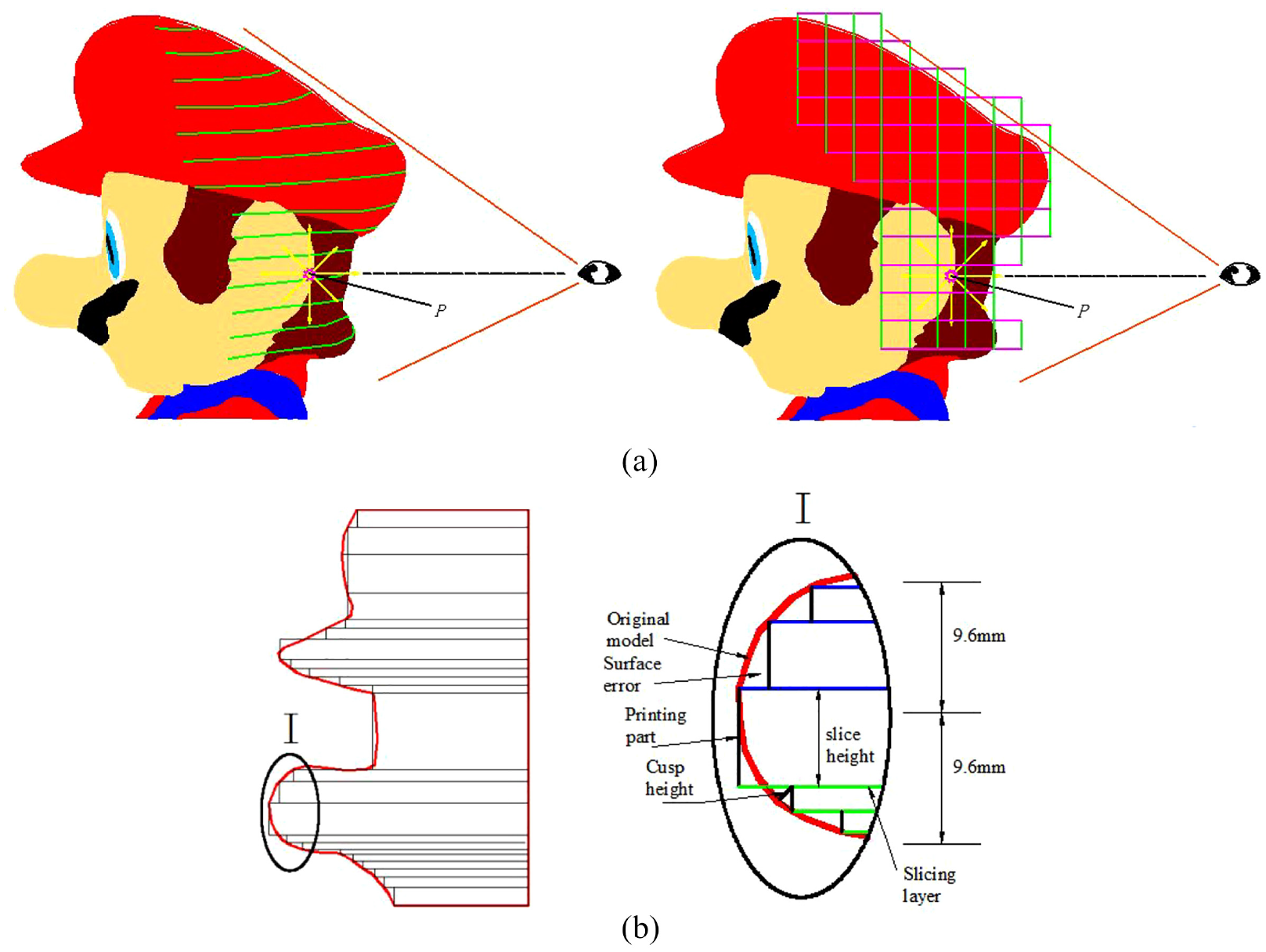
Schematic diagram of determination of LEGO unit bricks and their colors: (a) a comparison of determination of LEGO unit bricks and their colors using our algorithm and voxelization algorithm 1 and (b) Effect on adaptive slicing strategy on surface errors: the left is the schematic diagram of printing effects, and the right is partial enlargement of domain I for clearly illustrate.
Furthermore, a machine learning-based approach is employed for filling the initial LEGO model layer by layer by using appropriate LEGO bricks to achieve a hollow LEGO model. The system schematic of these procedures is shown in Figure 4 and the results are illustrated in Figure 5.
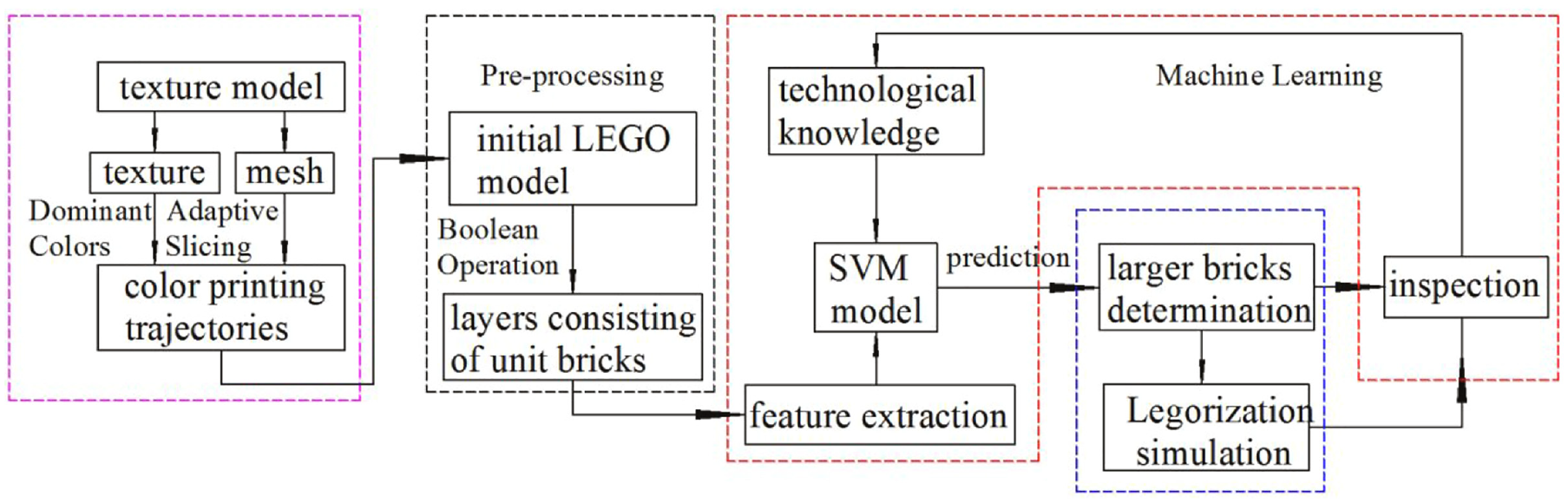
System schematic.
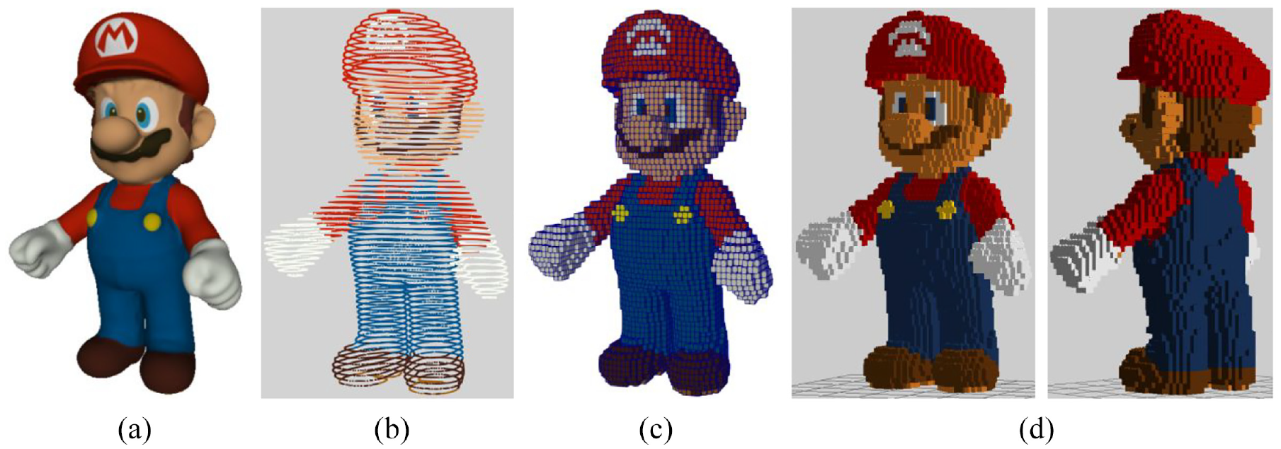
Our method transforms an input texture model (a) into an LEGO sculpture (d) that can be realized in the digital world: (a) input 3D model, (b) 3D color printing trajectory, (c) initial LEGO model, and (d) reconstructed sculpture.
The remaining part of this paper is organized as follows. In Section 2, the related work is reviewed. In Section 3, a method used to reconstruct an initial LEGO model (consisting of unit LEGO bricks) from 3D color printing trajectory is presented. The initial LEGO model is converted to a hollow model consisting of larger bricks using support vector machine (SVM) in Section 4. In Section 5, the effectiveness of our method using some complex examples are demonstrated. Finally, we conclude the paper in Section 6.
Related research work
Realizing physical representations of 3D models
A great deal of research has been presented for realizing physical representations of 3D models, which enabled the production of objects for a wide variety of purposes and materials have included paper crafts, 4 plush toys, 5 origami, 6 pop-up paper architectures,7,8 planar sections, 9 puzzles,10,11 wire mesh sculptures, 12 etc. Moreover, LEGO is one of the physical representation methods and all most all existing LEGO construction works are composed of two stages: voxelization and Legorization.
Voxelization
In order to visualize, animate, compute, and analyze geometric object (e.g. triangles, polygons, triangle meshes, and parametric surfaces) with computers, discretization of a geometric object in the real space is indispensable. 13 As one of the most widely used discretizing approaches, voxelization can convert a continuous geometry into an array of voxels in 3D discrete space while preserving their shapes. 14 It plays an important role in computer graphics and on the application side, such as virtual reality, 15 medical imaging/visualization, 16 and collision detection. 17 The triangle/box overlap tests are based on testing every potential voxel candidate for determine whether it intersects a triangle.18,19 A distinctly drawback of the methods is that the computation could be relatively expensive, compared to the 3D scan-conversion algorithms. 20 The 3D scan-conversion algorithms are extensions of their 2D versions (i.e. pixelizes 2D geometric objects). Unfortunately, the extension is not straightforward since voxelized surfaces cannot defined as an ordered sequence of voxels and a voxel on the surface does not have a specific number of adjacent voxels. Not only can this process take a significant fraction of the overall computing time, but this process can produce resulting voxelization only a subset of the cover of the original model. 13 Moreover, given the input watertight 3D model, voxelization consists of two steps when processing such a model and the computation procedure would be more expensive: the voxelization of the surface (exterior) of the model, followed by the voxelization of the interior of the model, which casts parallel rays through the model and uses parity count to classify voxels as interior or exterior. 21 Afterwards methods utilized the hardware resources to improve the computing efficiency were proposed. 22 However, none of these methods took reasonably optimize the points involved in the calculation into consideration, the calculation efficiency, or voxelization quality cannot be guaranteed at the same time. The advanced AM technology can generate printing trajectories which maximize the efficiency under the given precision criteria. In this paper, we propose a method, which utilize the adaptive printing trajectories for generating LEGO unit bricks.
Legorization and optimization
Legorization is defined as a process that tiles the voxel model using a series of bricks, that is to say, it is a LEGO construction procedure. 23 Last decade has seen a great deal of literature on Legorization for 3D models, such as penalty function minimization method, 24 evolutionary method, 25 cellular automata method,26,27 and randomized greedy method, 28 to name a few. Surveys of much more work about Legorization research can be found. 29 Some researchers presented their research efforts to solve the optimized construction problem. These optimization methods mainly focused on three fundamental criteria: structural stability, appearance, and effectiveness. Muller et al. 30 combined LEGO bricks with 3D printing for personal prototype design. It can be classified as an optimized appearance method. Luo et al. 31 presented a stability-aware refinement iteratively method which can perform the stability analysis and local reconfiguration to gradually improve the overall stability of the sculpture. Obviously, it emphasized on solving stability problem. Sugimoto et al. 32 used an industrial manipulator as a robotic “Block (brick) Printing System” and introduced a brick feeder to performs assembly of bricks. It was an optimized efficiency method. Afterwards methods to improve the various fundamental criteria were proposed: that is, Yun et al. 33 presented a Legorization scheme satisfying stability, esthetics, and efficiency in a tiling equation which is minimized through A* algorithm. Kozaki et al. 34 proposed an energy minimization scheme for Legorization which is minimized through simulated annealing algorithm. However, based on the fact that these works commonly employed merging approaches that merges FLU bricks into larger bricks, leave 1 × 1 × 1 bricks very frequently and the final layout fails to present balanced and esthetic visualization. Therefore, in this paper, a machine learning approach is employed that can automatically determine suitable sized bricks at their appropriate locations, which prevents the usage of FLU bricks and improves the quality of reconstruction.
Slicing algorithm
The slicing trajectories (including internal and external trajectories) for each layer can be obtained by finding all the triangles in the model that intersect with the given slicing plane and sequentially linking these intersections into corresponding closed polygons. 35 The technology of distinguishing between internal and external trajectories can refer to parent-and-son relationship and hierarchy-sorting algorithm. 36 Usually, research on the slicing processes for AM can be divided into two main categories of uniform slicing and adaptive slicing of the model. 37 For the former slicing method, the layer thickness of the rapid prototyping process is fixed through the entire process for the former slicing method, whereas, for the latter one, the layer thickness varies with the tolerance requirements. After studying the existing advanced adaptive slicing algorithms, in order to guarantee the reconstruction accuracy of the LEGO model, in this paper, the slice heights are computed by the adaptive slicing method which is similar to the one presented by Panda et al. 3
Machine learning
Currently, the researches on machine learning for manufacturing mainly have been focused on parameter optimization and shape error compensation.38,39 These works were mainly based on the principle of neural network. However, based on the usage of empirical risk minimization (ERM) criterion to minimize the sampling errors in the training process, the training result will inevitably lead to the over-fitting problem. The generalization ability of the model is limited. 40
Compared with neural network and other methods, statistical learning methods use training data to obtain classifications that model the relationships within the training data set. 41 An efficient statistical learning algorithm is the SVM which is based on the principle of structural risk minimization (SRM), 42 and its generalization ability is strong. Not only can it avoid problems such as over-learning and falling into local minimum, but it requires fewer samples, which is especially suitable for small sample training. In previous study, many machine learning research which are considering the generalization capability of produced model were based on SVM model and they can be used to optimize structure design and implement 3D reconstruction. 43 To the best of our knowledge, the existing Legorization strategies have not simultaneously resolved the problems of guaranteeing computation efficiency, reducing the use of unit bricks, and guaranteeing reconstruction accuracy of LEGO model.
Reconstruction method for unit LEGO bricks
Our inspiration comes from AM technology. We employ recent advances in computer graphics and 3D color printing techniques to facilitate the reconstruction of an initial LEGO model.
Substituted pixel colors by dominant colors
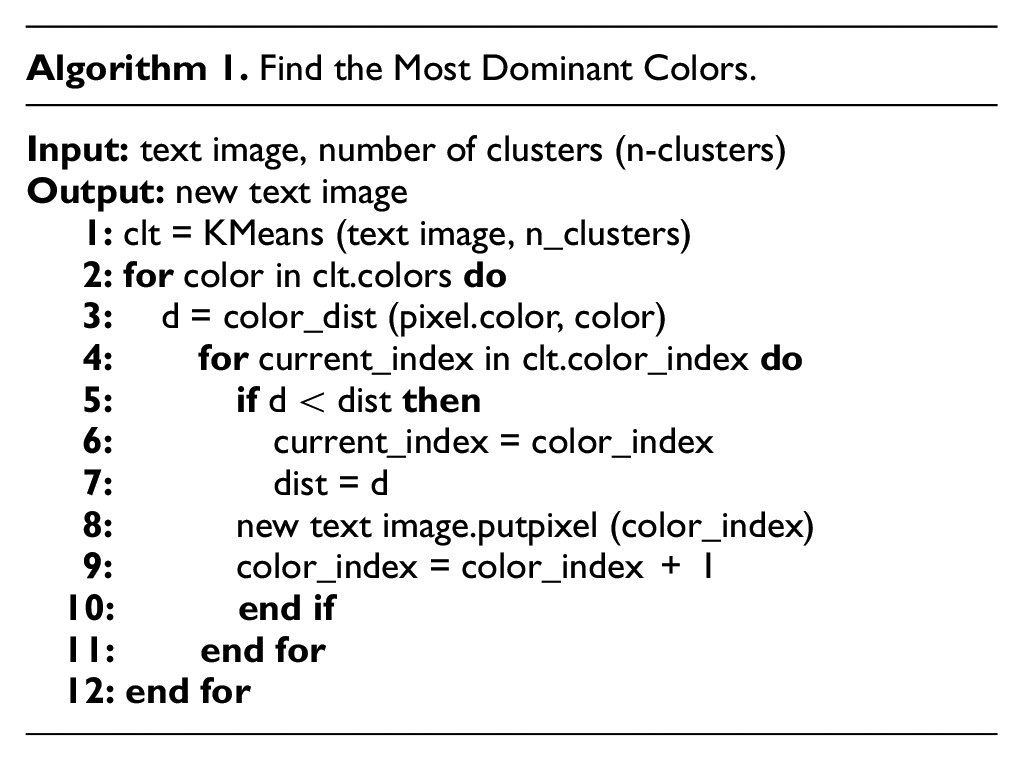
Actually, LEGO bricks provide limited colors and some gradient colors in the image cannot be realized. Therefore, an algorithm which can automatically pull out the colors that are represented most in the image (dominant colors) is as follows: Given an M × N size texture image, it denotes M × N pixels, each consisting of three components: Red, Green, and Blue (RGB). In the following, several functions which are used in Algorithm 1 are provided. The k-means clustering algorithm which can cluster the pixel intensities is used to find the most dominant colors in an image. 44 These M × N pixels will be treated as data points and be clustered: by specifying the number of clusters, the most dominant colors can be generated (line 1). Moreover, by traversing each pixel of texture image, the squared euclidian distance between two color vectors can be calculated (line 3), the closest color and corresponding index in the cluster colors (line 5–8) can be found, and the pixel colors in texture image can be substituted by cluster colors (line 2–12).
In Figure 6(b), we take an example for illustrating the substituted effect: some non-dominant colors are substituted by dominant colors, for example, the original button color (yellow) is substituted by red color.
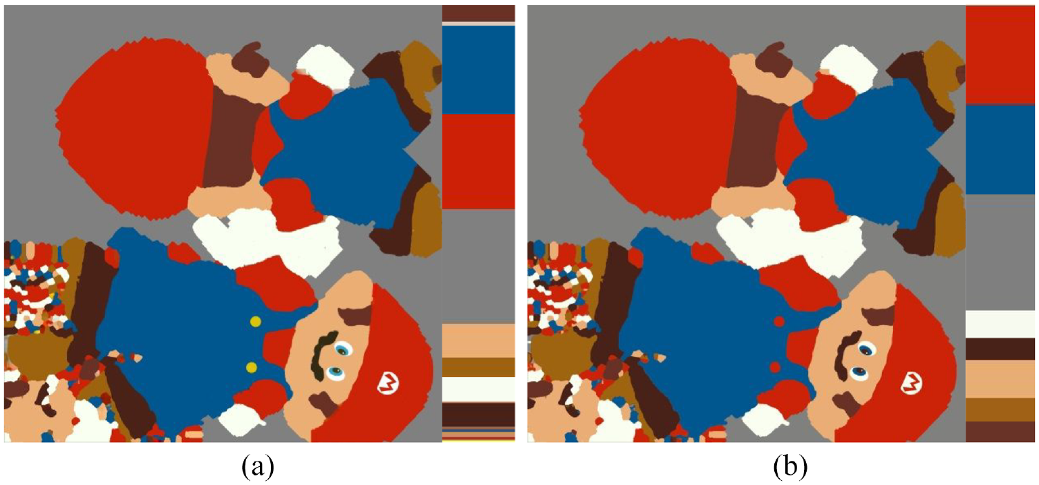
Substituted pixel colors by dominant colors: (a) original texture and (b) new texture with seven dominant colors.
Scaling effect
The relation between the initial LEGO model size and model size is linear. Let the scale factor k equals to 10 denotes the original size of the model. k can be any appropriate positive real number: k equals to 5 and 2.5 respectively denote half and one fourth size of the original model. Figure 7 shows the Mario model with three different dimensions (k = 2.5, 5, and 10).
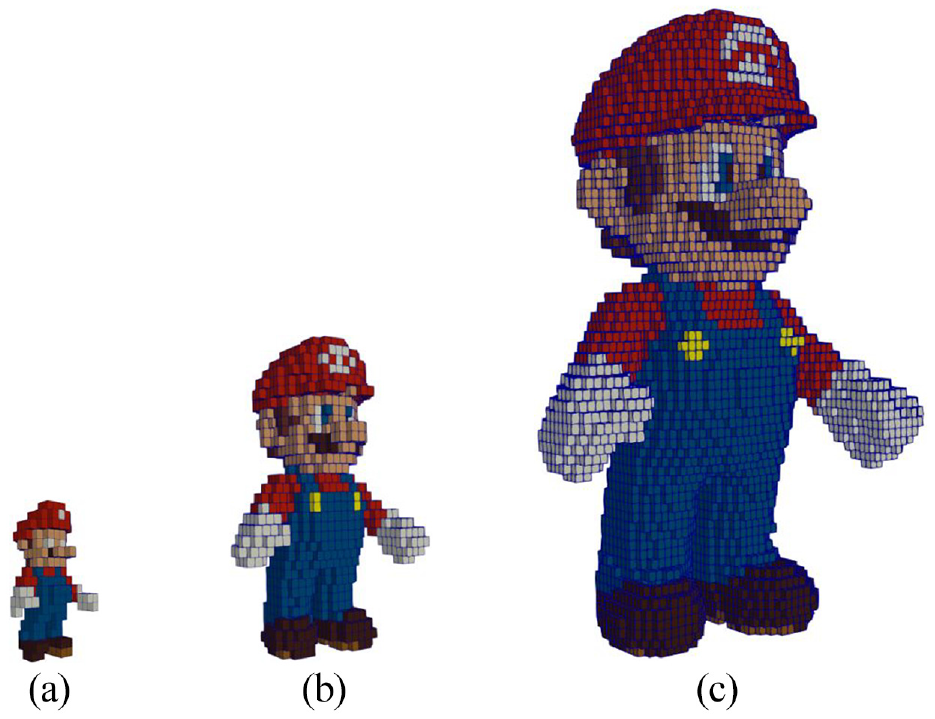
Three different dimensions (k = 2.5, 5.0, and 10.0): (a) 96 mm × 72 mm × 163.2 mm, (b) 208 mm × 144 mm × 316.8 mm, and (c) 408 mm × 272 mm × 633.6 mm.
3D color printing trajectory transform to LEGO bricks
The topological hierarchy relationship of the slicing results and a slicing example (the rendered colors of internal and external trajectories followed the rules in Figure 8(a)) of an Off-Road Vehicle (ORV) model are illustrated in Figure 8(c). In this paper, the slicing result follows a counter-clockwise rule for the exterior trajectories, and clockwise for the interior trajectories.
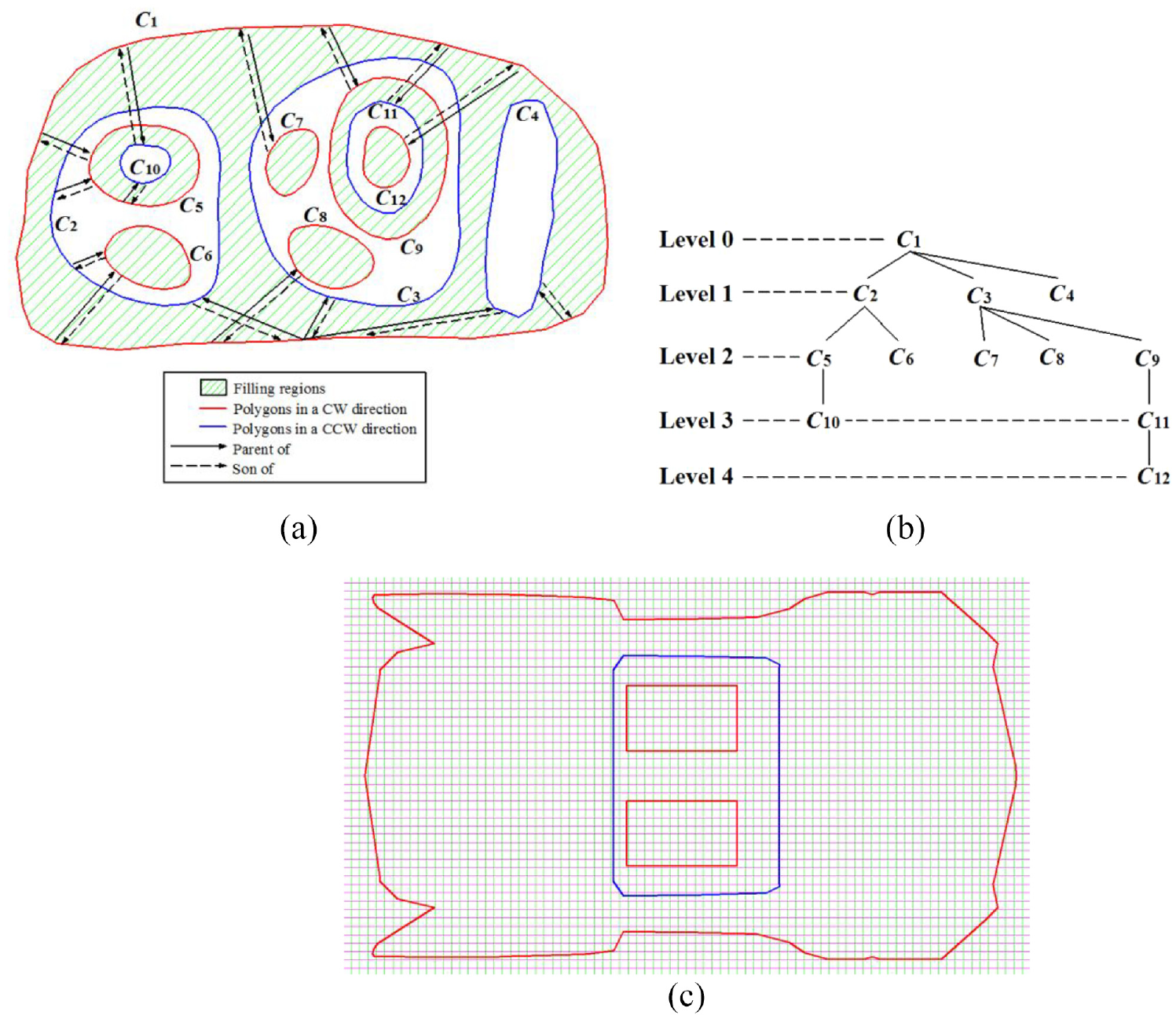
Illustration of topological hierarchy relationship of slicing results: (a) parent-and-son relationship, (b) topological hierarchy relationship, and (c) a slicing example of Off-Road Vehicle (ORV) model.
LEGO unit brick generation
Generation of rectangular polygon and multiple standard polygons
Consider a mesh surface S and a bounding box defined over it. Let the rectangular polygon of this bounding box be B. The polygons on S which correspond to a set of 3D color printing trajectories of i-th layer bounded by the range of the bounding box are generated based on an efficient rapid prototyping slicing algorithm for the surface. Let the slicing plane be parallel to the xoy-plane and let increment of z-axis direction be equal to 9.6 mm (a FLU in height). All trajectories generated from different slicing planes in the same interval of 9.6 mm should be processed layer by layer. B can be partitioned into multiple standard polygons with increment of x-axis and y-axis directions are equal to 8.0 mm (a FLU in length and width). In order to avoid the situation that there existing any 3D color printing trajectories passing through tiny polygons (located at the boundaries of B and the length or width cannot simultaneously reach to 8.0 mm), B should be enlarged by a scale factor α, for example, α = 1.1. The result is illustrated in Figure 9. The printing trajectory where point P is embedded, as illustrated in Figure 3(a), corresponds to the current slicing result we are processing. In order to distinguish it from the white background, the color of printing trajectories (their original color is white) is set as green.
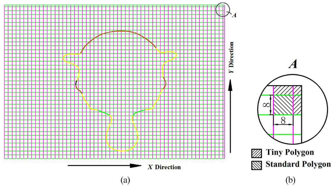
Rectangular polygon B and printing Trajectories: (a) 3D color printing trajectories located on B and (b) partial enlargement of domain A for clearly distinguishing tiny and standard polygon.
Classification of pass through types
The general cases of 3D color printing trajectories which pass through standard polygons can be illustrated in Figure 10. Let P0, P1, P2, and P3 be the vertices of a standard polygon; let
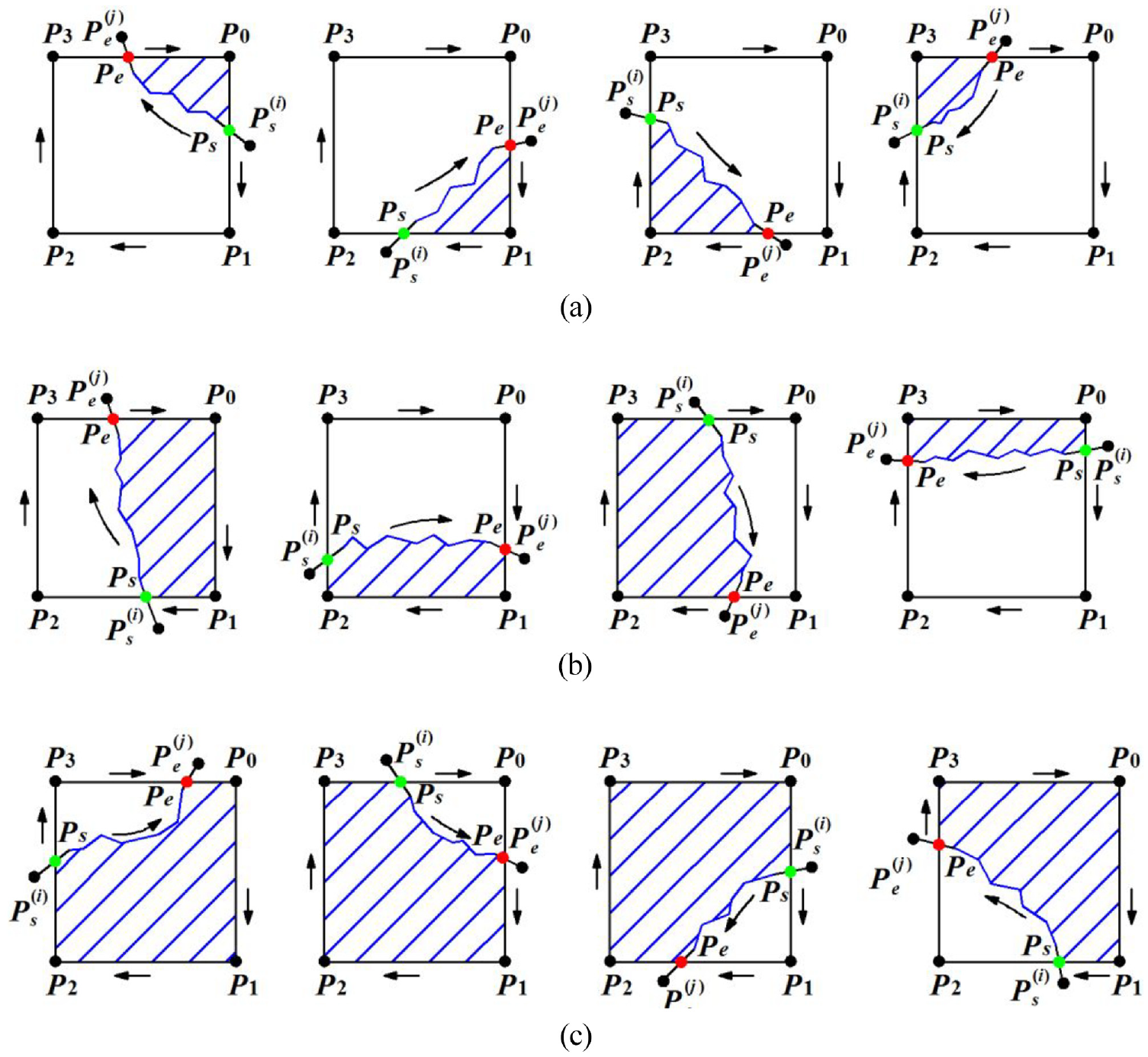
Three pass through types, contained: (a) one vertex, (b) two vertices, and (c) three vertices.
These general cases can be classified as three types according to the number of vertices contained in the new polygon. More complex cases (e.g. compass two or even more regions) can be the combination of these general cases.
Generation of LEGO unit bricks
We determine the standard polygon as LEGO unit brick by the composite criterion of area criterion of new polygon and the length criterion of printing trajectories which pass through standard polygons:
(1) The area can be used to judge whether the current standard polygon is valid or not: if the area is not reach the pre-setting threshold value, the current standard polygon is invalid and the inner polygon will be set as valid. In this paper, we set the threshold value as half of the area of standard polygon which is 32 mm 2 .
Take the above-mentioned general cases for example: in Figure 10(a), the lengths of different colors of line segments on new polygon between Ps and Pe may not reach area threshold value; in Figure 10(b), the area of new polygon with two vertices has to calculate and judge whether it reaches the area threshold value or not. If the area exceeds the threshold value, the current standard polygon is valid. In contrast, the current standard polygon SP is invalid and inner standard polygon SP′ which shared the same common edge (P0P1) with opposite direction is valid, as illustrated in Figure 11(b).
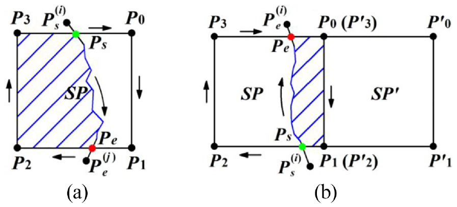
Judgment of area threshold value: (a) SP is valid and (b) SP′ is valid.
In Figure 10(c), the area of new polygon with three vertices may exceed the area threshold value, and the current standard polygon can be directly used to generate LEGO unit brick.
(2) Moreover, the length of printing trajectories which pass through standard polygons can be used to judge the color of the current standard polygon. Note that one LEGO unit brick may be passed through or surrounded by trajectory with different colors. We need to consider all these colors from outside of the brick at different angles. In this paper, we specify the color of standard polygon is the one with a maximum length of the trajectory.
We take current standard polygon as the center polygon and eight neighbor polygons with directions: up, down, left, right, and four diagonal directions for color calculation. The inner, the former, the latter polygons and the ones have not passed through by trajectory will not participate in the calculation. Therefore, in most cases, we only need to compute the lengths of different colors of printing trajectory in at most three polygons. Let the total lengths of printing trajectory in the standard polygon be ltotal and let the length of one kind of the colors be lij. They are related by the following formula:
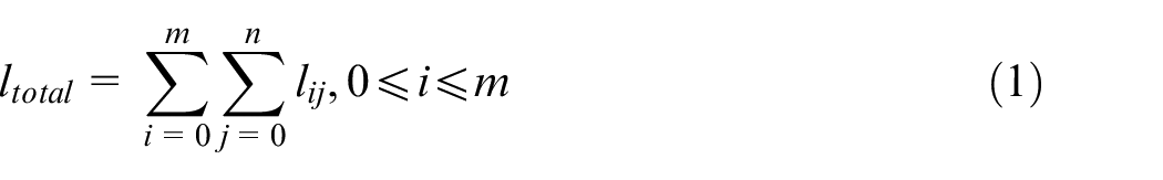
where m denotes the total number of dominant colors selected from the texture image, i is the current index of colors, and n is the number of line segments in current color.
After determining the valid polygons, we compute the cumulative lengths of different colors from the printing trajectory which is passing through current valid polygon and other eight polygons around it. Take the following cases for example, as illustrated in Figure 12: let the SPi be the current valid polygon. Therefore, after removing the former (SPi−1), the latter (SPi+1), the inner (DOWNi), the ones have not been passed through (DOWNi and its adjacent two neighbor polygons of left-side and right-side), we only consider SPi, LEFTi, and RIGHTi for the determination of color with maximum length of the trajectory. Based on the same principles, if the SPi+1 is the current valid polygon, we considerUP-RIGHTi+1 and RIGHTi for the determination of color of SPi+1.
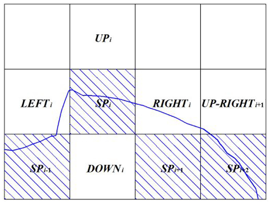
Demonstrate principles of determination of position for current polygon.
In Figure 13, we illustrate this generation procedure of initial unit bricks.
Initial unit bricks generation.
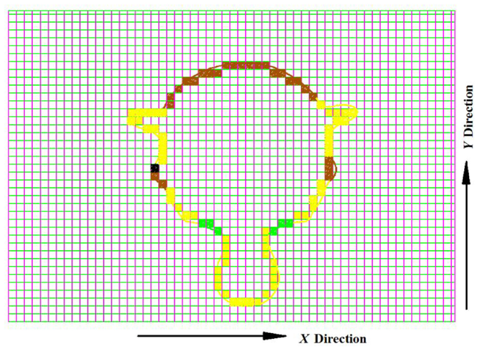
Local “high-resolution.”
Combined with differences between neighboring layers can mark the regions as “high-resolution” to indicate that these should later be 3D reconstructed with plates. The judging criteria of differences can be summarized as: (1) numbers of polygons of neighboring layers and (2) lengths and areas of corresponding polygons of neighboring layers. Trajectories from three adjacent slicing layers are illustrated in Figure 14(a), and the projection results of the initial unit bricks are illustrated in Figure 14(b).
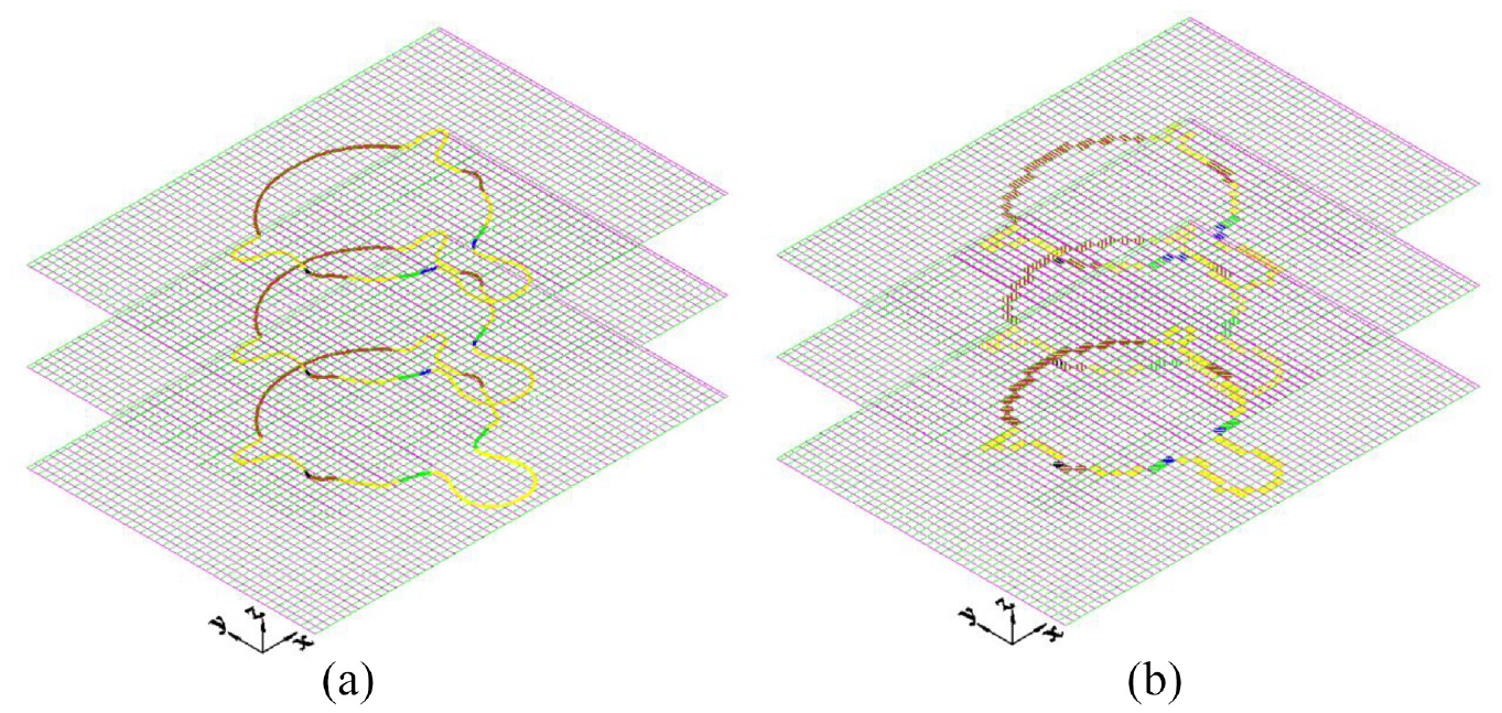
3D Southwest isometric side view: (a) trajectories and (b) projection results.
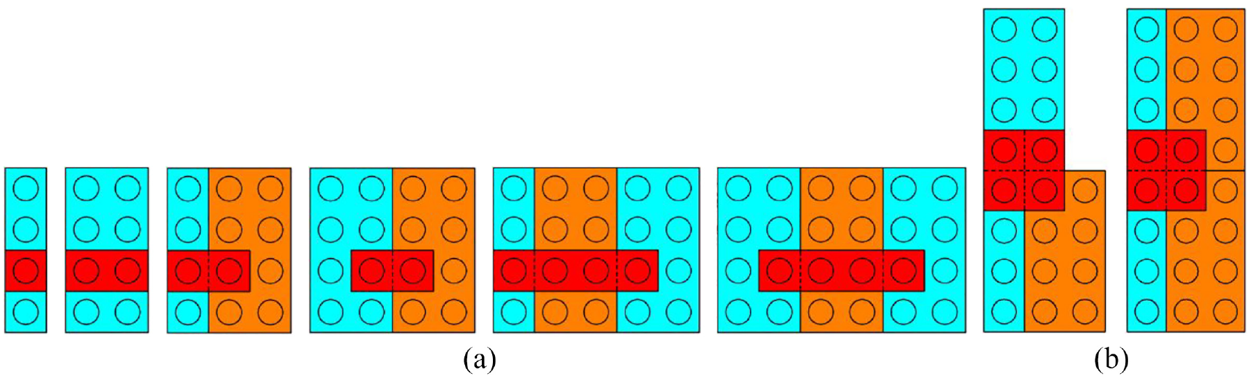
In Figure 15(a), we illustrated three layers of plates which are superimposed over one another with different angles. The reconstruction effect of LEGO unit bricks is illustrated in Figure 15(b). To simplify the solution of this superimposed problem, we use only one direction (horizontal or vertical) to make the determination of standard unit bricks and the superimposed cases can be generalized with number of colors, as illustrated in Figure 15(c) to (e).
(l) If there are three plates located in a same grid (left), these three plates can be merged into one standard unit brick;
(2) If there are two plates located in one grid and the remaining plate is located in another grid (middle), the valid standard unit brick is the one where two plates are located;
(3) If three plates are located in three different grids (right), the valid standard unit brick is the one where the middle plate is located.
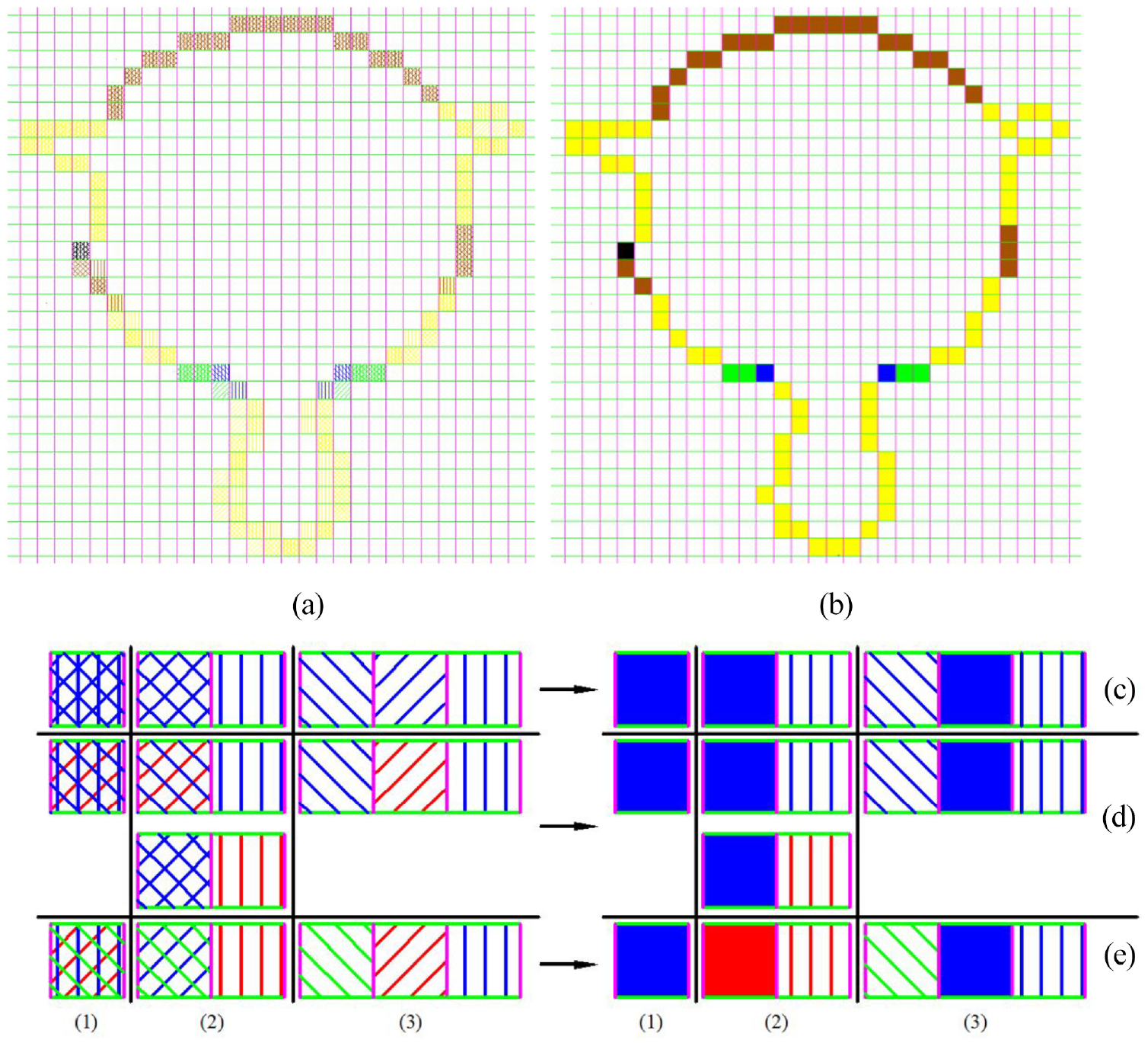
Reconstruction by plates: (a) three layers superimposed over one another, (b) reconstruction effect, and (c–e) are superimposed cases.
The valid standard unit brick can refer to
The valid standard unit brick can refer to
Figure 16(a) and (b) show the Mario head which reconstructed with standard bricks and plates, respectively. In Figure 16(b), more details on face and hat brim of the model are presented. The choice of “high-resolution” is important as a higher value results in a better approximation of the original object, but would require more bricks and more time to build. Therefore, we can use three trajectories with the interval is equal to the height of a plate (3.2 mm) for substituting one trajectory with the interval is equal to the height of a standard brick (9.6 mm) for “high-resolution,” as illustrated in Figure 16(c).
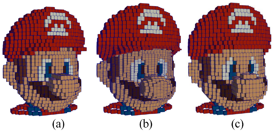
Mario head reconstructed by: (a) unit bricks, (b) plates, and (c) “high-resolution” solved by three trajectories.
Offsetting and support bricks generation
Overhang regions judgment and offsetting bricks generation
Some models have overhanging parts, which means that parts of the trajectory float mid-air after slicing the model. Vanek et al. 45 presented three types of overhangs: that is, point, face, and edge overhang. The point and face types are illustrated in Figure 17(a), and the edge type is defined similarly to face overhang. A point can be classified as point overhang if it possesses lowest z value in local region among neighboring points. A face needs support if the angle between the face plane (f1 or f2) and the printing direction (z-axis) is higher than the critical angle αc (α1 < αc < α2), as illustrated in Figure 17(a). Similarly, we have to plan criterion for judging overhang regions for Legolization. By implementing LEGO unit bricks generation procedure described in previous chapter, as illustrated in Figure 17(b), the horizontal span of bricks in blue color is relatively large (14 times of FLU) and cannot be expressed by one kind of common used brick with which the length is six times of FLU. Moreover, the overhang parts may come in different colors. In order to implement Legolization more accurate, the trajectory must be offset for judging colors of those overhanging parts of the model.
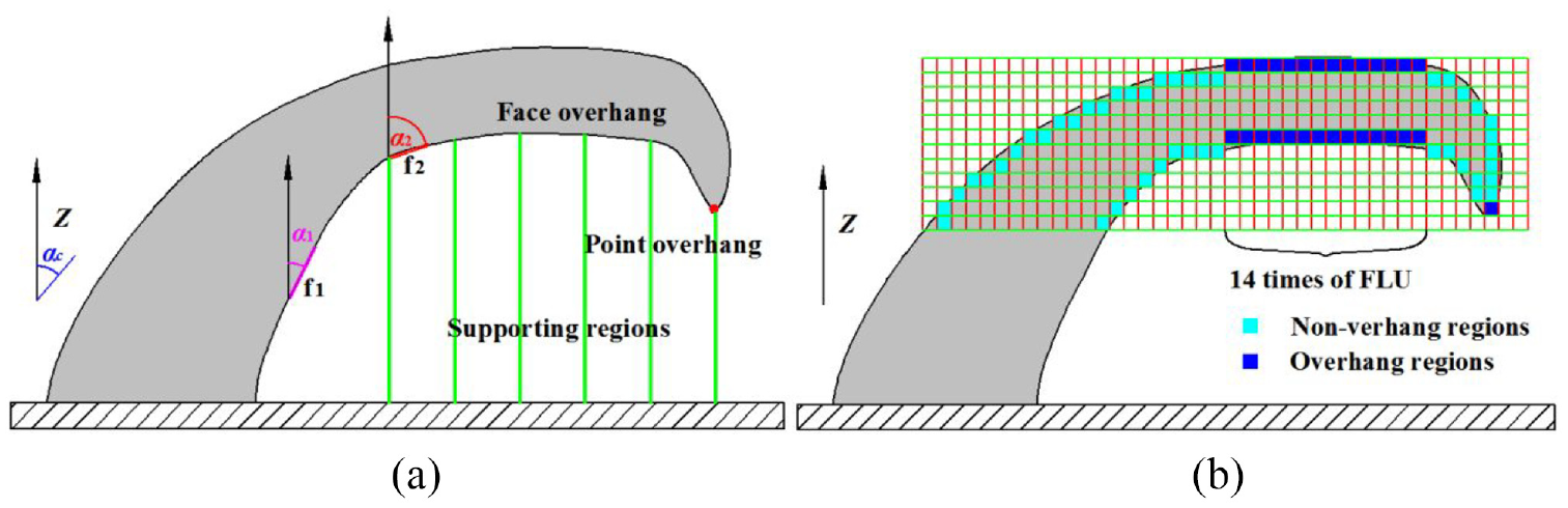
Point and face overhangs regions: (a) 3D printing and (b) Legolization.
In Figure 18, after generating LEGO unit bricks, point p and point p′ are defined directly on the center of the unit LEGO bricks with adjacent height and same y value. Direction z indicates the building direction. In a 2D setting, the judging criteria of the offsetting region generation is:
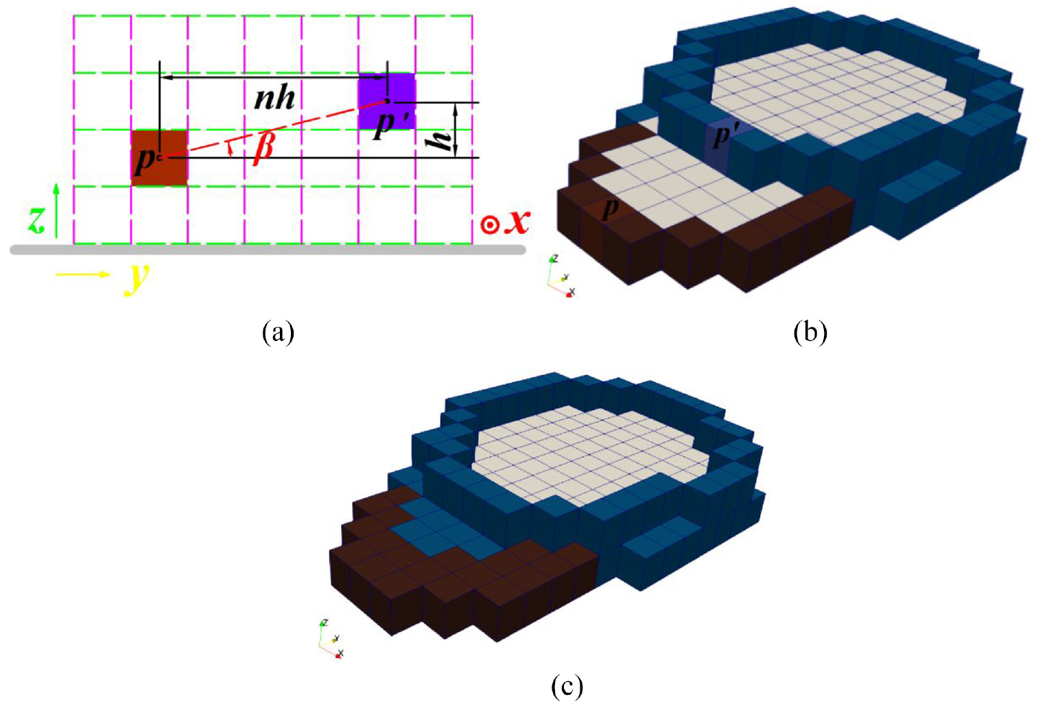
Definition of offsetting regions S in 2D and 3D versions. Points p and p′ are defined directly on the center of the unit LEGO bricks with adjacent height. Direction z indicates the build direction: (a) 2D region, (b) 3D region, and (c) offsetting unit LEGO bricks.
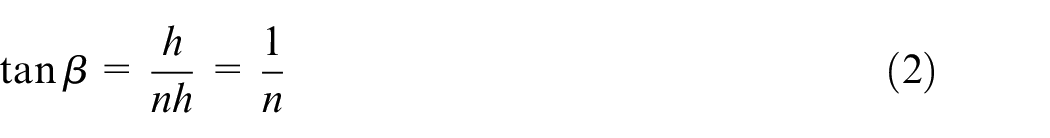
where, n denotes the number of span bricks, h denotes the height of a LEGO brick and the tan trigonometric function (syntax: tan β) to calculate the tangent of an angle in radians. Obviously, if n equals 0 or 1, we do not need to offset the trajectory; if n is relative large, there exists region where must be filled with color bricks, we implement the offsetting operation and project the offsetting trajectory to current plane. Then, the projecting trajectory can implement LEGO unit brick generation. In this work, the offsetting trajectory is computed by the method presented by Sun et al. 46 It provided computation methods of offsetting trajectory from point set (the set of points which is between two adjacent trajectories). These procedures will execute until the n is equal to 1. The unit bricks which are generated from offsetting procedures and located in the inner region of upper bricks will be deleted. The offsetting distance (e.g. integer multiple of 8.0 mm) is specified as a constraint allowing for a small deviation of surface colors.
In Figure 19(a), the overhanging parts of the model need to generate a support structure to prevent the LEGO bricks from falling down. As shown in Figure 19(b), the offsetting regions and support regions can be computed. The offsetting results of these regions are illustrated in Figure 19(c).
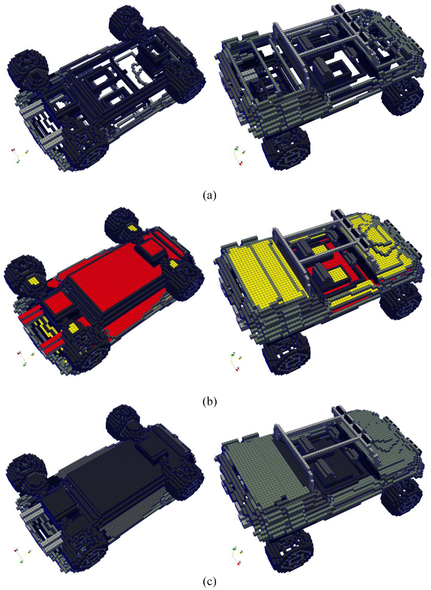
Judgment of offsetting regions and support regions, and the offsetting operation procedures: (a) initial LEGO unit bricks, left: bottom side; right: top side, (b) offsetting and support regions, left: bottom side; right: top side; yellow: offsetting regions; red: support regions, and (c) implementing offsetting operations, left: bottom side; right: top side.
Support bricks generation
Optimization frameworks which can guarantee supporting strength for the reduction of support structures have been deeply researched for saving 3D printing time. In this paper, the ideas in advanced supporting techniques are borrowed for generating support structures for Legorization: These optimized (intermediate) support structures can be transformed into support bricks for Legorization and finally be manually removed after Legorization.
Take the fennec fox model with support structures for example, as illustrated in Figure 20(a), the tree structure is employed for automatically generating an initial support structure which deviates from the support volume and instead builds a thin structure for supporting the part in a sparse, limited number of points.
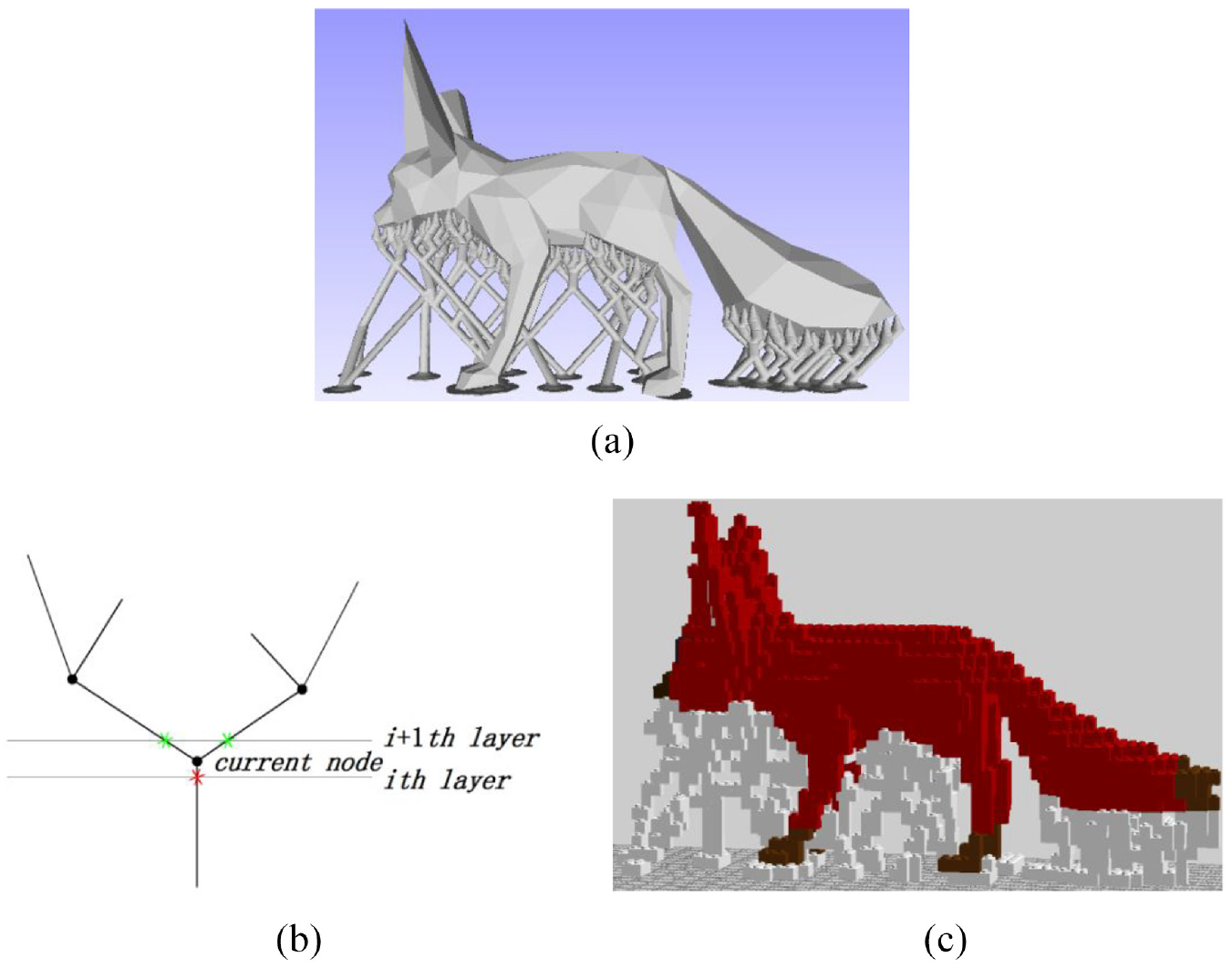
Support structure and support bricks of fennec fox model: (a) the strut diameter (from top to bottom) is dynamic: the top one is thinner than the last one as it is supporting less weight, (b) the schematic diagram of slicing result, and (c) the integrity of support structures can be reserved.
The conversion process can refer to previous chapter. However, in order to guarantee that there reserves enough integrity of support structures, all the nodes have to be transformed into support bricks. Take one branch for example, in case of the current node is located between the i-th and i + 1-th slicing layer, as illustrated in Figure 20(b), the number of polygons generated by neighboring slicing layers intersect this branch is increased from one (shown as red star symbol) to two (shown as green star symbol). We formulate that the current node should be moved to the red star symbol of the i-th layer and transformed into corresponding support bricks. The support effect is illustrated in Figure 20(c).
Legorization segmentation
Another way to reduce build volume is segmenting the model into multiple parts: after appropriately segmentation and implementing Legorization for these parts respectively, some support bricks which are originally inside can be removed and these divided parts can be eventually combined into one entirety.
Considering the cases that the heights of support bricks are relatively low and can be removed, a simplified support structures which only contains beam and steady is formulated as the following rules:
(1) Direction y indicates the length direction and direction x indicates the width direction;
(2) Choose the constant several combinations for construction of support structure, as follows:
type 1: 1 × 1 × 1, 1 × 2 × 1, 1 × 3 × 1, 1 × 4 × 1, and 1 × 6 × 1;
type 2: 2 × 2 × 1, 2 × 3 × 1, 2 × 4 × 1, and 2 × 6 × 1;
type 3: 2 × 2 × 3 and 2 × 4 × 3.
The numbers indicate length, width, and height of integer multiple of FLU.
(3) The calculation sequence is length (Direction y), width (Direction x), and height (Direction z).
From the first column of the support bricks, the total number (b1) of bricks along Direction y can be divided by maximum number (let it be equal to six times of length of FLU) of selected bricks with a remainder be divided sequentially by other lengths (i.e. the second and the third maximum number: 4 and 3) of selected bricks with a remainder of not equal to 1 to the greatest extent. The distribution result can be filled in the following matrix:
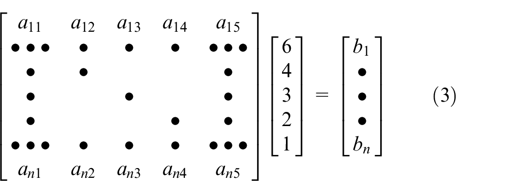
Obviously, aij is equal to 0 or 1 (i ≤ n and j ≥ 2). Every two neighboring rows with the same bricks will be merged into a brick with the same length and two times of width of FLU. Note that the beam structure can be omitted and be substituted as actual construction of LEGO bricks. Particularly, if bi to bj are equal to 1, they can be merged into several bricks with transposed configurations (i.e. 1 × 1 × 1, 1 × 2 × 1, 1 × 3 × 1, 1 × 4 × 1, and 1 × 6 × 1) according to the same above mentioned distribution rule.
We recommend applying 1 × 2 × 1 and 1 × 4 × 1 bricks for linking relatively short beam structure (i.e. the length is equal to or less than four times of length of FLU). Moreover, for the length is equal to six times of length of FLU, we recommend applying 2 × 2 × 1 and 4 × 2 × 1 bricks for linking neighboring bricks. The linking brick is located at approximate barycentric coordinates of neighboring beam bricks along y direction for support stability considerations. Therefore, the case of linking only one stud on beam bricks which are relatively large (i.e. the length is equal to or more than four times of length of FLU) has to be prevented, as illustrated in Figure 21.
Linking examples of pillar structure: (a) short beam structure and (b) long beam structure.
For each beam bricks, the total number of bricks along Direction z can be divided by 3 (as mentioned before, it is the number which we selected maximum times of height of FLU) of selected bricks with a remainder be divided by 1 (LEGO provide only one and three times of height of FLU). As illustrated in Figure 22, we generate the beam and steady bricks of support structures. Note that we do not choose longer (2 × 6 × 1) or thicker (2 × 6 × 3) bricks for building steady structure for the cost and more accessible of these selected bricks.
Construction of support structures, left: lower half; right: upper half.
Most of the support bricks can be removed and these divided two parts can be eventually combined into an ORV model (as illustrated in the experimental verification Section).
Automated generation of LEGO building instructions
The initial boundary unit LEGO bricks, which contain color information, should be replaced by larger bricks without changing the boundary shape or color. In this paper, a machine learning method based on SVM is employed and finally the output building instructions provide a brick placement diagram for each layer.
Basic LEGO bricks
We restrict our LEGO construction scheme by employing 12 basic brick sizes with the height of FLU: 1 × 1, 1 × 2, 1 × 3, 1 × 4, 1 × 6, 1 × 8, 1 × 2 × 2, 2 × 2, 2 × 3, 2 × 4, 2 × 6, and 2 × 8. The numbers represent the number of rows × columns of the studs of each basic LEGO brick. These basic bricks can be transposed by reversing the number of rows × columns, in the assembly process, resulting in nine different kinds of bricks to select for construction. Note that the 1 × 2 × 2 type possesses three different transposed configurations.
Overall framework of the proposed larger sized bricks determination model
The overall framework of the larger sized bricks-based classification model proposed in this paper can be mainly divided into the following four steps:
Step 1. Example preparation. We start the initial building scheme (layer-based approach) with an initial LEGO model consisting of unit bricks with color information assigned to the surface boundary bricks. If the solid LEGO model can be hollowed out as much as possible, the resulting LEGO model will be light and economical. Therefore, the difference (Boolean Operation) results of bounded regions enclosed by current and upper layers’ projection rectangular polygons need to be computed. Let the current and upper bounded regions be Rc and Ru, respectively. According to the inclusion relationship of Rc and Ru, the difference results (layers consisting of unit bricks) can be generalized as four cases, as illustrated in Figure 23(a) to (d).
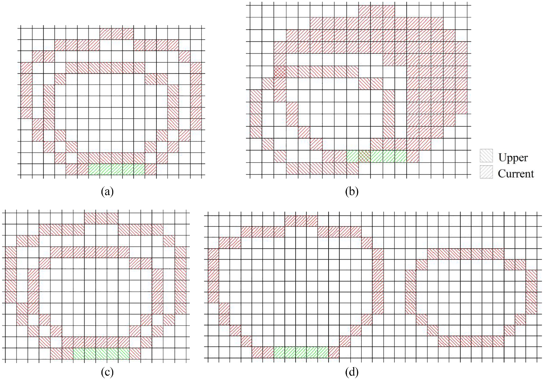
Four difference cases, contained: (a) Ru⊆Rc, (b) Ru∩Rc≠Ø, (c) Ru⊇Rc, and (d) Ru∩Rc = Ø.
The filling region Rf can be expressed as

where (Rc − Ru) denotes Ru is removed from Rc, Ru_outer is the set of outer rectangular polygons of Ru.
The filling region Rf can be expressed as

where Rc_intersect_u denotes the set of outer rectangular polygons which is belong to Ru and intersects with Rc.
The outer rectangular polygons of Rc can be used to support Ru. Therefore, the filling region Rf can be expressed as

where Rc_outer is the set of outer rectangular polygons of Rc.
The current layer can be regarded as local top layer. Therefore, the filling region Rf can be expressed as

where the solution of Rc_fill can be referred to previous chapter for computing offsetting bricks. Moreover, if there exits new layer (Ru), we employ the method described in previous chapter to compute supporting bricks for Ru.
Step 2. The extraction of feature values. There are four feature values, including: circularity, stability, symmetry, and efficiency need to be calculated.
Step 3. The multi classification model generation. The four features are combined and the LIBSVM classifier are used to train these features, so as to obtain the classification model.
Step 4. Experimental samples classification. Furthermore, by comparing and analyzing the relationship between classification results and building errors, technological knowledge is constantly generated. The acquired knowledge is applied within the filling process for generating new model to predict the classification of new layers of the initial LEGO model.
The SVM is a smart unit that directly controls the classification system and provides intelligent decision making according to the feedback from the filling simulation for every polygon. In the following, we describe the above contents in detail and analyze the training results.
Example preparation
To prepare data for both analysis and machine learning, five typical models were sliced and suitable layers consisting of unit bricks originate from initial LEGO model were selected as samples. We employed some LEGO fans to build these LEGO models with various sizes of bricks. We calendared the layers consisting of unit bricks and corresponding building bricks as examples.
Let D = {x1, x2,…, xm} be the data set which contains m samples. Each sample may contain d features, let each sample xi = {xi1, xi2,…, xid} be one feature vector of sample space X in d dimension. In this paper, we prepare m = 1500 samples and compute d = 4 feature values for each sample.
Feature extraction
Minimum unit connection
Minimum unit connection is used to reduce the use of unit bricks. The less unit bricks the layer used, the more stable the layer is. Simultaneously, this can improve the building convenience and efficiency. There are various types of continuous and scattered unit combinations, the objects of this feature extraction are specifically refer to the group of unit bricks which contains not less than two bricks and the neighboring center connection line is forty-five degree. As illustrated in Figure 24, they are two pairs of unit bricks which are shown as black “×” symbol. If each pair of unit bricks are in the same color, they can be reconstructed by 1 × 2 × 2 brick. The term for the minimum unit connection is defined as follows:

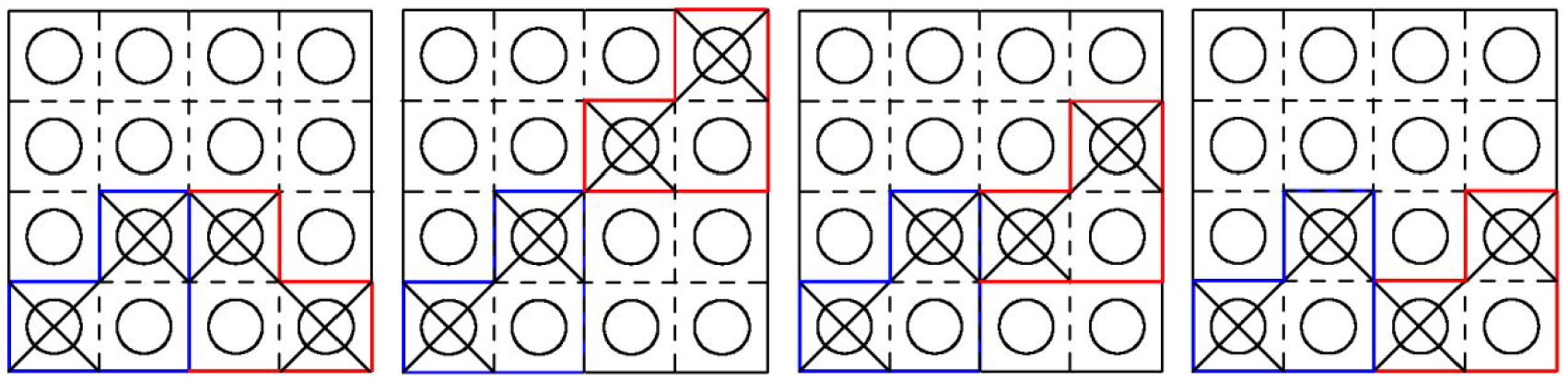
Reconstruction work of two pairs of unit bricks: the blue and red closed polygons denote two 1 × 1 × 1 bricks.
where n is the total number of FLU bricks used in the current layer.
Stability
Stability is used to pursue a stable layout of bricks during the construction process along vertical and horizontal directions. The first term measures the local stability, where higher values indicate lower stabilities. The more studs that hold current brick together, the smaller energy becomes.
Vertical directions
We estimate the vertical stability that exists between upper and lower bricks. The equation which can estimate the number of studs that hold current brick is given by:
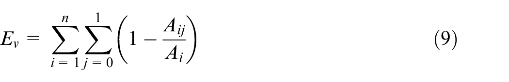
where n is the total number of FLU bricks used in the current layer, Ai denotes the area of current brick, and Aij denotes the area that are overlapping with upper (j = 0) and lower (j = 1) bricks. Figure 25(a) illustrates the case where a 2 × 8 brick is sandwiched by three bricks: the upper side exist one 2 × 2 brick and one 2 × 3 brick, the lower side exists one 1 × 4 brick. In this case

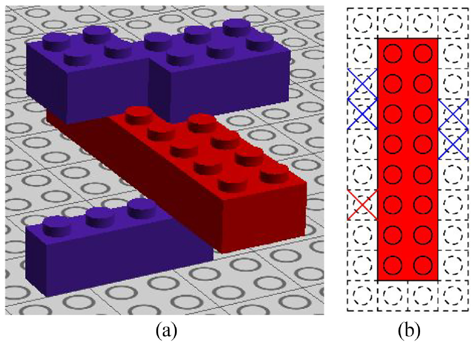
Stability evaluation: (a) a simple 3D example illustrating neighboring layers and (b) the blue cross indicates the areas that are overlapping with the upper bricks, while the red crosses indicate area that is overlapping with lower bricks.
Horizontal directions
We estimate the horizontal stability that exists between upper and lower bricks. The maximum size brick used in this research is 2 × 8, and the area of maximum surrounding studs is 24. The equation which can estimate the number of studs that hold current brick is given by:
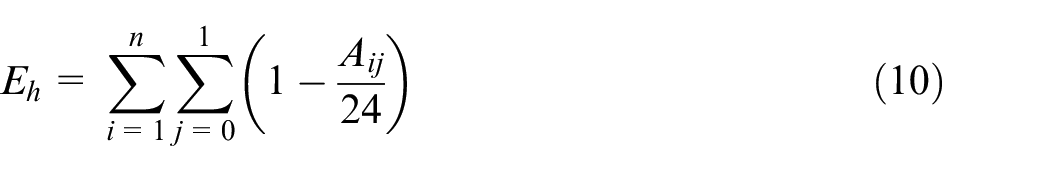
where Aij denotes the area that are overlapping with upper (j = 0) and lower (j = 1) bricks in the surrounding region. For example, the upper side of current brick (the red one) in Figure 25 has four horizontal overlapping LEGO unit areas, yielding Ai0 = 4, while the lower side has only one horizontal overlapping LEGO unit area, yielding Ai1 = 1. Hence, Eh = 43/24.
Symmetry
Symmetry is used to evaluate a symmetric layout of layer which constrains the unit bricks to be arranged along the axis of the model. Considering the symmetry in construction artwork, not only can the symmetrical structures bring players esthetics feelings, but can symmetric building give players construction efficiency: the more symmetrical a layout is, the less types the bricks chooses. We assume that z-axis is orthogonal to the slicing layers and central axis is either x-axis or y-axis. A brick is symmetrical, if the central axis passes through the center of the brick or there is a mirrored brick which has the same color for the axis. The term for the symmetry is defined as follows:
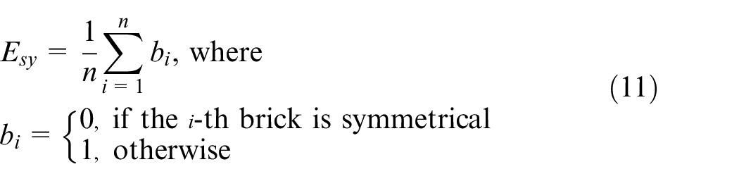
Figure 26 illustrates the filling effects that mirrors bricks according to the axis and estimates Es. The red line is central axis.
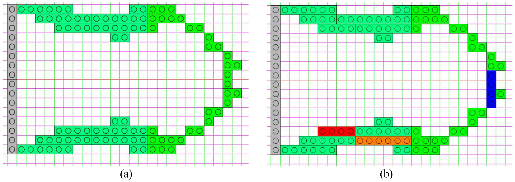
The comparison of symmetric filling: (a) 29 bricks with Es = 0/29 = 0 and (b) 29 bricks with Es = 13/29.
Efficiency
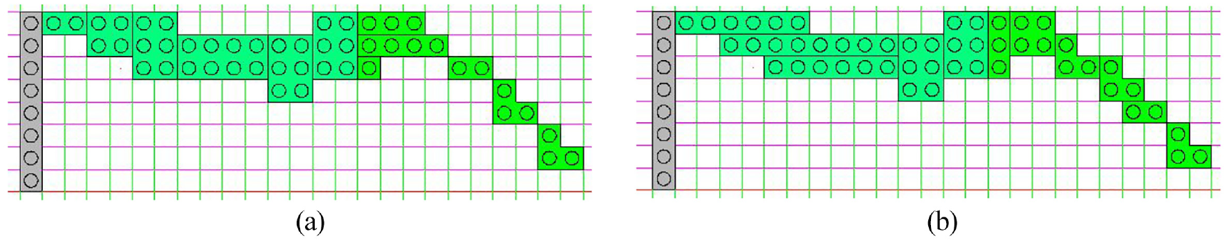
We pursue the building efficiency of the LEGO model by saving the number of bricks in the minimum cost and time. Many researchers proposed big brick for their filling principle that merges several small bricks into a big brick. For a horizontal big brick, we estimate the area of the brick as follows:
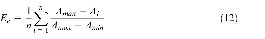
Obviously, if we use FLU bricks for building an initial LEGO model, the Ee of each layer is equal to constant 1. Figure 27 illustrates the filling effects that merge bricks and estimate Eh. The red line is central axis.
The comparison of efficient filling: (a) 13 bricks with Ee = 0.7795 and (b) 12 bricks with Ee = 0.7444.
Legorization based on LIBSVM
After extracting features from layers consisting of unit bricks, the features are combined together as the final feature vectors of the layers. In order to avoid the situation where multiple attributes are there but attributes have values on different scales, Gauss normalization technology 47 has to be implemented to scale the attribute value of each dimension in the same range of [0, 1].
After preparing the training samples, we call the svm-train function for generating a SVM model and call the svm-predict function 48 for classification prediction. In this paper, the Gaussian kernel function is selected and the fivefold cross-validation can be used to find the best values for these parameters. By considering our samples are evenly divided, we chose micro-average compared to macro-average because it cares about overall data (not prefer to any class). 23
Numerical simulation
In this section, we first compare the resulting layouts with respect to the choice of three weights. Then, we demonstrate the effectiveness of our algorithm by testing on two complex models, namely, (i) Mario, an (ii) Off-Road Vehicle (ORV), (iii) Pokemon’s Mega Charizard Y, (iv) Fennec Fox with different support structures, and (v) a Cartoon Toy Tiger, and produce their assembly maps. All the computations were implemented on a PC with Pentium i7 CPU, 12 GB RAM, and NVIDIA GTX 1060 graphics card with 6 GB of GDDR5 RAM. The graphics card can serve up smooth, stable performance in engineering, research, and modern video and games at 1080p resolution. We implement the Legorization work by generating and storing the LEGO model as a simple txt file: the .ldr format file from our program. Then the .ldr format file can be opened by in LEGO model design or rendering software, for example, Lego Digital Designer (LDD), Lego Studio, and LDview. In this paper, we use LDD software to render Legorization result and check the model assemble-ability.
Data statistics
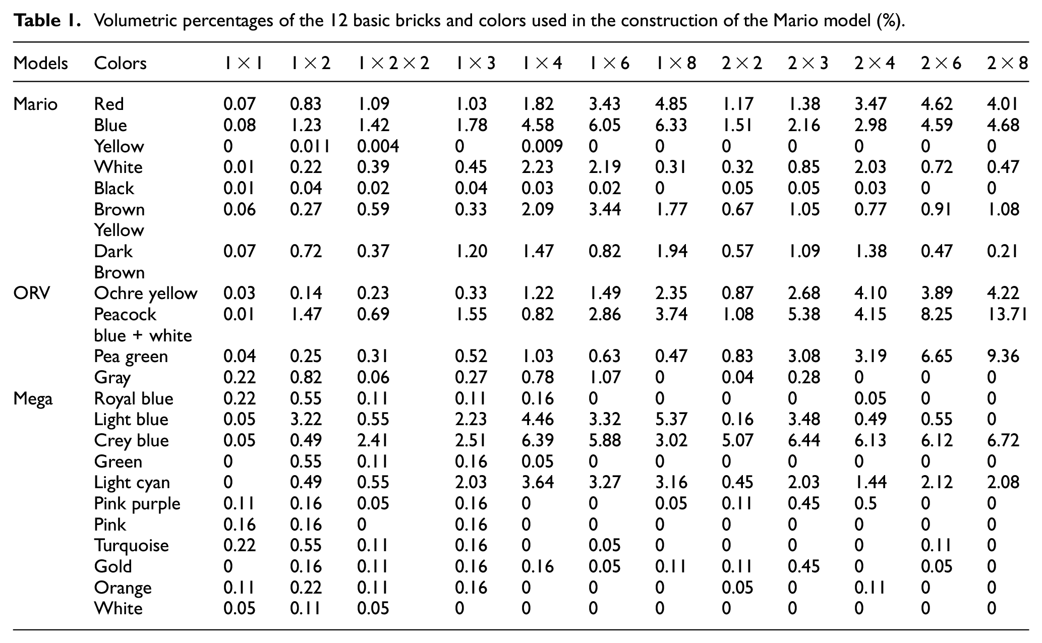
The input models are illustrated in Figure 28. We list the number of bricks for each of the 12 basic bricks as well as for each color used in the Legorization in Table 1. It is clear that the larger size bricks are more used than the smaller bricks. This clearly shows that Ee is effective.
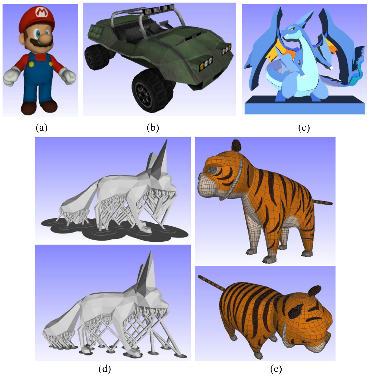
Input models: (a) Mario, (b) ORV, (c) Mega Charizard Y, (d) Fennec Fox with different support structures, and (e) Cartoon Tiger.
Volumetric percentages of the 12 basic bricks and colors used in the construction of the Mario model (%).
For the third model, as illustrated in Figure 28(c), based on the fact that each of its slicing layers are the same, we implement procedures of offsetting outer boundaries of the upper surface of the model and generate a mosaic painting. This can prove the flexibility of our method. In order to clearly showing CPO tool paths, we only select a few of them for rendering.
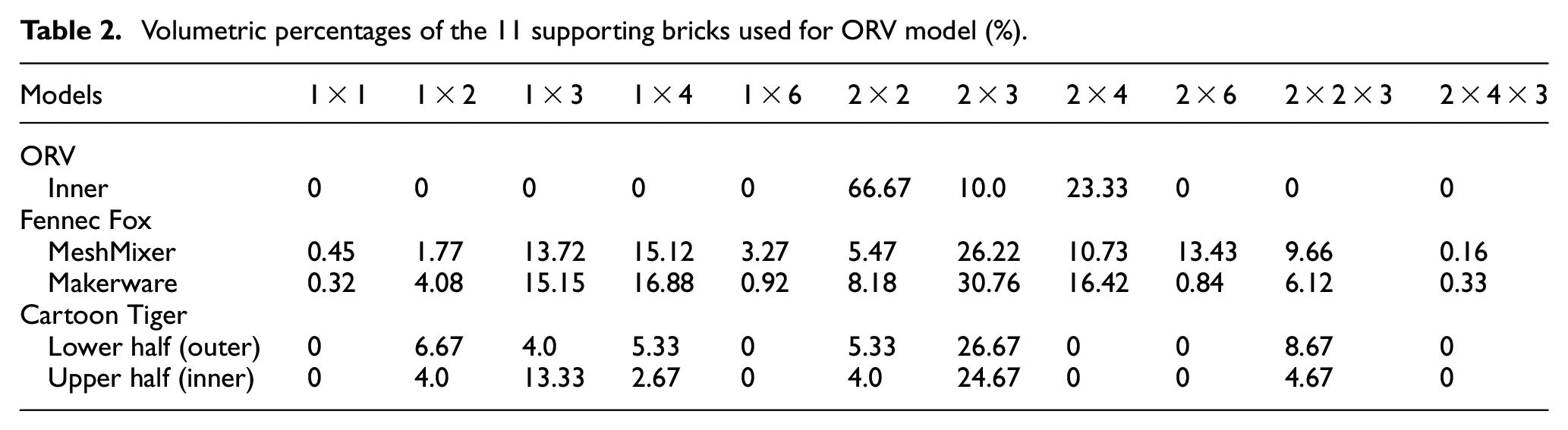
For the models which are illustrated in Figure 28(b), (d), and (e), we focus on the application of advanced supporting technology used for Legorization. We list the number of bricks for each of the 11 basic bricks used for supporting in Table 2. The different support structures of Fennec Fox model are generated by MeshMixer and Makerware. For the support structures of ORV and Cartoon Tiger, we refer to the Clever Support method 44 for generating 3D printing support structures and convert them to LEGO support structures. It is clear that an optimization framework for the reduction of support structures is necessary. The more effective an algorithm is, the simpler support structure becomes.
Volumetric percentages of the 11 supporting bricks used for ORV model (%).
Legorization
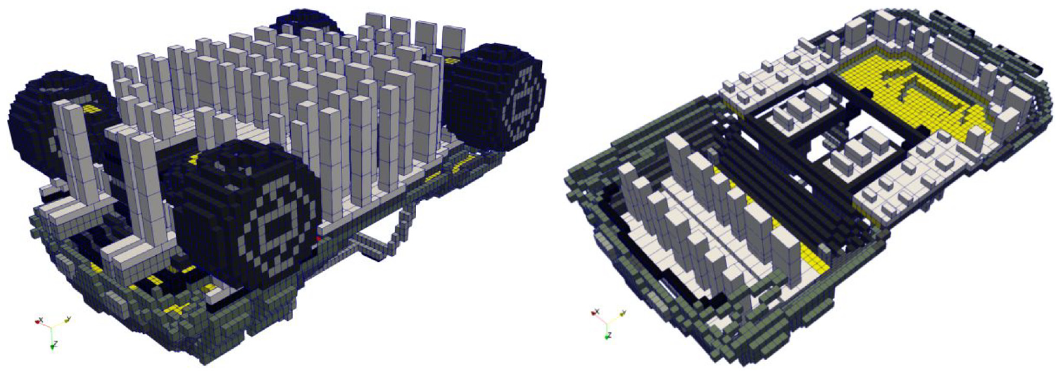
We apply LEGO Digital Designer (LDD) for implementing construction. Our Legorization results are illustrated in Figure 29 and the Legorization procedure can be comparable with actual constructing and must strictly abide by the laws of physics: for example, the overhanging structures cannot be built if we do not use supporting bricks. As mentioned before, in actual construction, supporting bricks are required to build overhanging structures. In order to illustrate clearly, the outer support bricks are rendered in white color and the inner support bricks are rendered in red.
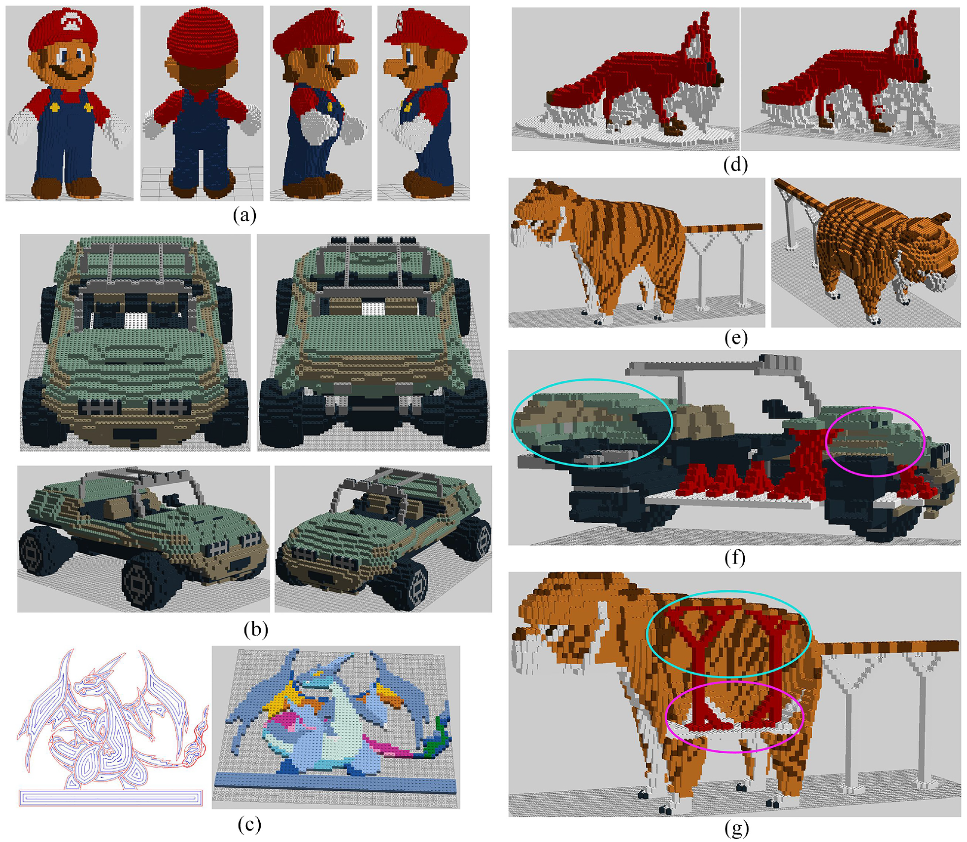
Reconstructed models: (a) Mario, (b) ORV, (c) Mega Charizard Y, (d) Fennec Fox with different support structures, (e) Cartoon Tiger, (f) vertical section of the ORV model, and (g) vertical section of the Cartoon Tiger model.
All most all the external supporting bricks can be removed after construction, except for the tail of Tiger, as illustrated in Figure 29(e). In order to constructing the chassis (i.e. overhanging structure) that spans a wide dimension on both x and y directions, we use 2 × 8 and 1 × 8 (or transposed) white bricks on both sides of the ORV’s central axis, as illustrated in Figure 29(f). The external supporting bricks of chassis can be completely removed because the internal supporting bricks (red support structures) have an interlocking mechanism: they can support the upper half of ORV and attach the lower half of chassis. The back and abdomen of Tiger are overhanging structures, from which the inner support structures cannot be removed, as illustrated in Figure 29(g).
Compared to final reconstructed effect in Figure 29(f), the regions selected by red and pink ellipses which do not span that wide on either x or y directions, the inner supporting bricks can be removed after the assembled upper half is self-supporting. Then we can attach the two halves together to complete the Legorization work.
Comparison and discussion
We make comparison to Legorization methods presented by Kim 29 and Yun. 32 While our method can successfully generate Legorization results for the above-mentioned models, the previous methods failed at the overhanging structures. For the comparison, we neglect the support structures and only quantify the hollow out ratio (Hor), number of bricks (Nb), and time-consuming for Legorization (Tc) of the Legorization results from ours and other two methods. We list the results of comparison in Table 3.
Summary of the comparison of Legorization results for each model.
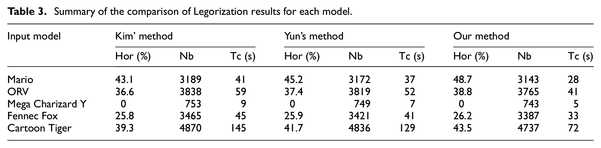
According to the comparison, our approach shows better Legorization results than these methods. We speculate the significant superiority of computational efficiency is based on the fact that the machine learning method can efficiently reconstruct initial LEGO model; moreover, the advantages of hollow out ratio and number of bricks is based on the fact that our Legorization method can accurately transformer unit bricks into larger bricks and reduce the usage of FLU bricks.
We make comparison to support method presented by Kozaki. 33 We evaluate the weight (unit: g) and number of bricks (Nb) of the support results. The comparison results are listed in Table 4.
Summary of the comparison of supporting structure for each model.
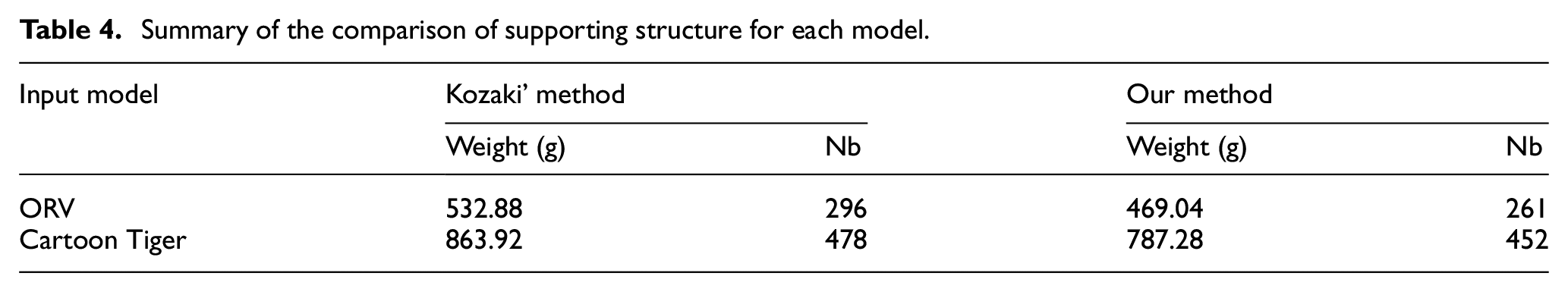
According to the comparison, our approach shows better supporting results. This means that the tree supporting structure which is thin and sparse can effectively simplify structure and reduce weight.
Conclusions
In this paper, a Legorization scheme which based on 3D color printing trajectory is proposed. It preserves the inner and outer structures of input model, transformers adaptive trajectory into initial LEGO unit bricks, and guarantees quality and efficiency of Legorization work by employing machine learning method. The construction problem of supporting bricks are considered for solving the buildability problem. Some complex models with inner structures are tested and results demonstrate superiority of the proposed method. The method proposed in this paper can mainly solve the following problems:
By combining advanced adaptive slicing algorithm with building “high-resolution” regions with thin plates, the reconstruction accuracy of initial LEGO units can be guaranteed.
Comparing to existing reconstruction work, the method presented in this paper has the significant superiority of computational efficiency: machine learning method can efficiently reconstruct LEGO model; moreover, the number of points involved in determining LEGO unit bricks is far less than the voxelization method.
The advantages of hollow out ratio and number of bricks is based on the fact that our Legorization method can accurately transformer unit bricks into larger bricks and reduce the usage of FLU bricks.
The tree structure employed for automatically generating supporting structures which can effectively simplify supporting structure and reduce support weight.
Overhanging and required supporting regions can be determined and supporting bricks can be generated in actual construction; by adopting split assembly appropriately and implementing combination of these parts accurately, the supporting structures can be further reduced.
This study represents the first attempt to apply machine learning for Legorization, and the proposed algorithm could be improved in some regards, such as optimization processing. Therefore, to achieve better performance and make the Legorization algorithm more intelligent, we will focus on improving the modeling and training methods in future research.
Footnotes
Declaration of conflicting interests
The author(s) declared no potential conflicts of interest with respect to the research, authorship, and/or publication of this article.
Funding
The author(s) disclosed receipt of the following financial support for the research, authorship, and/or publication of this article: The authors are grateful for the support provided by National Key Research and Development Project (grant no. 2018YFB1105300), National Natural Science Foundation of China (grant no. 51605475), and The central government guides the local science and technology development fund plan (grant no. 2021JH6/10500123).