
Abstract
An efficient isogeometric-based framework is presented to integrate optimum design and formability analysis of sheet metal forming processes. To assess the quality of the formed parts, several objective functions such as fracture, wrinkling, thickness variation, and stretching are studied. In this framework, geometric parameters of addendum surfaces and middle tools are considered as design variables, the objective functions are calculated using the recently developed one-step and multi-step inverse isogeometric methods, and the optimum design variables are obtained using the genetic global optimization algorithm. The major advantage of employing the inverse methods is to analyze the formability of the parts with a low computation time. In this research, the effects of altering addendum surfaces and/or middle tools on the quality of the formed parts are simultaneously observed since modeling, formability analysis, and optimization stages of sheet metal forming simulation are integrated using the NURBS functions. To evaluate the performance of the inverse isogeometric models in calculation of the studied objective functions, the results obtained by these models are compared to those of experiment and forward FEM. Comparisons of the results indicate that these models predict the objective functions with acceptable accuracy at a low computation time. For instance, in sheet metal forming analysis of a rectangular box with three different addendum surfaces, the maximum error in prediction of minimum thickness using the one-step inverse model is approximately 4.65% more than forward FEM, while the solution time of forward FEM is around 40 times greater. Finally, the presented optimization procedure is applied to design addendum surfaces in forming of a rectangular box and the middle tools in a two-stage drawing of a square box. The results of these problems confirm the credibility of the present approach in rapid optimum design of addendum surfaces and intermediate tools with acceptable accuracy.
Keywords
Introduction
Many automobile parts are manufactured by sheet metal forming processes (SMFP) which depend on various parameters. To understand how different parameters can affect the quality of the achieved products, computational approaches, including forward and inverse finite element methods,1–8 have been frequently developed in both academic and industrial endeavors. Forward approaches using the incremental theory of plasticity predict more accurate results, compared to inverse models based on the deformation theory of plasticity. However, a costly trial-and-error process is intrinsically involved in forward methods, in contrast to the inverse models in which reasonably accurate results are achieved at a low computational cost. The inputs of inverse models include the geometry of the final part, the initial blank thickness, and material properties of the studied sheet, which are available at the initial design stages. 5 Because quick estimation of the forming severity is essential in the initial design stages, the inverse methods are frequently used in these stages.
Several research studies9–22 were conducted to optimize SMFP, considering different objective functions, design variables, forming solvers, and optimization algorithms. In these works, it was shown that the quality of the formed parts is affected by changing blank-holder/draw-bead forces and geometric parameters of the forming processes. For instance, Debray et al. 9 demonstrated the significant effects of addendum surfaces on the quality of the formed parts. Therefore, an appropriate design of addendum surfaces can help to reduce fracture and wrinkling problems. In the literature, different objective functions such as fracture, wrinkling, stretching, springback, surface aspect, and thickness variation were studied for quality assessment of the formed parts. Also, different design variables including the addendum surface parameters, draw-bead restraining forces, and blank-holder force were selected. Furthermore, computational approaches like forward and inverse finite element methods were utilized to analyze the SMFP, and different optimization methods such as Pareto-based genetic algorithm,12,13 genetic algorithm (GA), 10 response surface method (RSM),9–12,14,15 and feasible sequential quadratic programming (FSQP) 9 were implemented to calculate the optimum solutions.
Formability analysis of the formed parts drawn in several stages with considering the middle tools was studied using forward and inverse finite element models in several research studies.7,8 However, in multi-step forming processes, the optimum middle tools have not been suggested to achieve the desired quality of the parts so far.
In many research studies done to optimize forming processes, finite element and inverse finite element models were employed to numerically simulate these processes. As FEM-based models separately use modeling and analysis representations, these methods require a long time for preprocessing and mesh generation stages of the simulations. Therefore, implementation of FEM-based models in the iterative optimization procedure demands tremendous computational costs.
To eliminate the gap between the modeling and analysis representations, Hughes et al. 23 proposed isogeometric analysis (IGA). In this methodology, the computer-aided design (CAD) technology is employed. For instance, non-uniform rational B-spline (NURBS) functions are utilized to simultaneously draw and analyze the part in the NURBS-based IGA. This methodology makes it possible to integrate CAD and computer-aided engineering (CAE). Besides, high smoothness of the basis functions and high continuity for high-order basis functions are achieved in this methodology. Therefore, many research studies have successfully utilized this method in various engineering fields such as shape/topology optimization problems24,25 and analysis of shells and plates.26,27
IGA has also been successfully used in simulation of forming processes. For instance, Benson et al. 28 studied the stamping process using an isogeometric shell element in a forward incremental approach. In the inverse approach, Zhang et al. 29 and Wang et al. 30 proposed a one-step inverse isogeometric analysis (IIGA) with and without considering bending effects based on the principle of virtual work. They used the initial solution presented by Zhang et al. 6 to solve the non-linear governing equations. Furthermore, Shamloofard and Assempour31,32 and Isazadeh et al. 33 presented the transfer-based one-step and multi-step IIGA models based on the minimum potential energy. They proved the ability of the transfer-based IIGA models to predict the initial blank and strains in short computation time.
Based on the literature review, the isogeometric methodology has not been applied to optimally design geometric parameters of SMFP so far. Moreover, no attempt has been made to predict the optimum middle tools in multi-stage forming processes. The present study focuses on these important issues. The objective of this research is to develop a new isogeometric-based framework that predicts optimum geometric parameters of the addendum surfaces and the middle stage tools. For this purpose, this procedure takes the advantages of the IIGA models to rapid calculation of the objective and constraint functions using the selected geometric variables. Then, the optimum design variables are computed by employing the GA. In the presented framework, the gap between modeling, analysis, and optimization stages of the simulations is eliminated using the NURBS functions. Therefore, the designer can quickly observe the optimum geometric parameters of the process at the initial design stages.
In what follows, the isogeometric concept and transfer-based IIGA models are briefly reviewed. Next, the capabilities of the IIGA models in calculation of the studied objective functions are experimentally and numerically investigated. Thereafter, a new framework is presented and applied to optimally design SMFP.
Preliminary study
In this section, general concepts of NURBS, IGA, and transfer-based IIGA models are briefly discussed.
NURBS
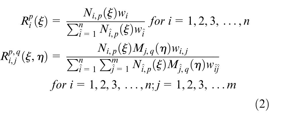
NURBS and B-spline are the most common parametric functions which are used in CAD. NURBS functions generalized form of B-spline are constructed by imposing weights to B-spline functions. Using a knot vector
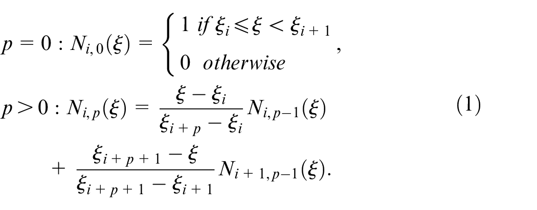
Where,
In which,
Using NURBS basis functions
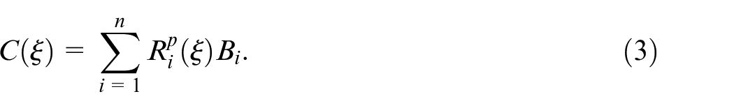
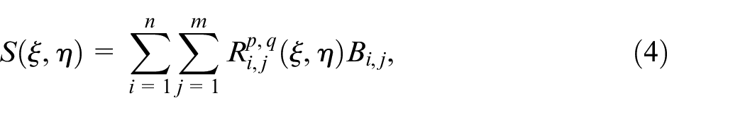
Similarly, using a control net
Alongside the exact modeling of the parts, the NURBS functions can be successfully used in analysis, due to the unique properties of these functions mentioned by Hughes et al. 23
Isogeometric analysis (IGA)
The main idea of the NURBS-based IGA is to employ NURBS functions for exact modeling of the parts and approximating field variables. In this methodology, the isoparametric concept is invoked using an exact geometric map, in contrast to FEM that employs an approximate geometric map. In IGA and FEM, a field variable (
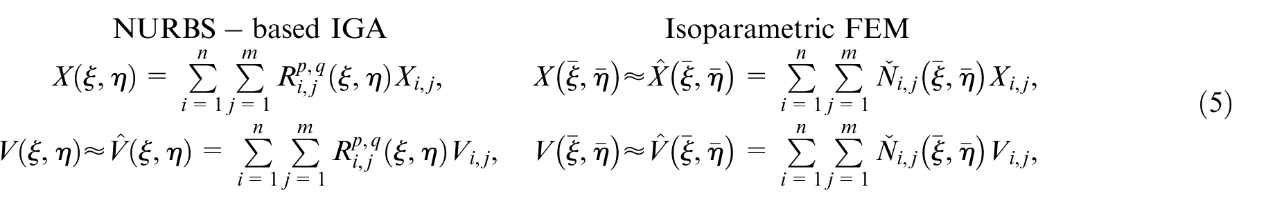
In which,
Inverse isogeometric (IIGA) methodology
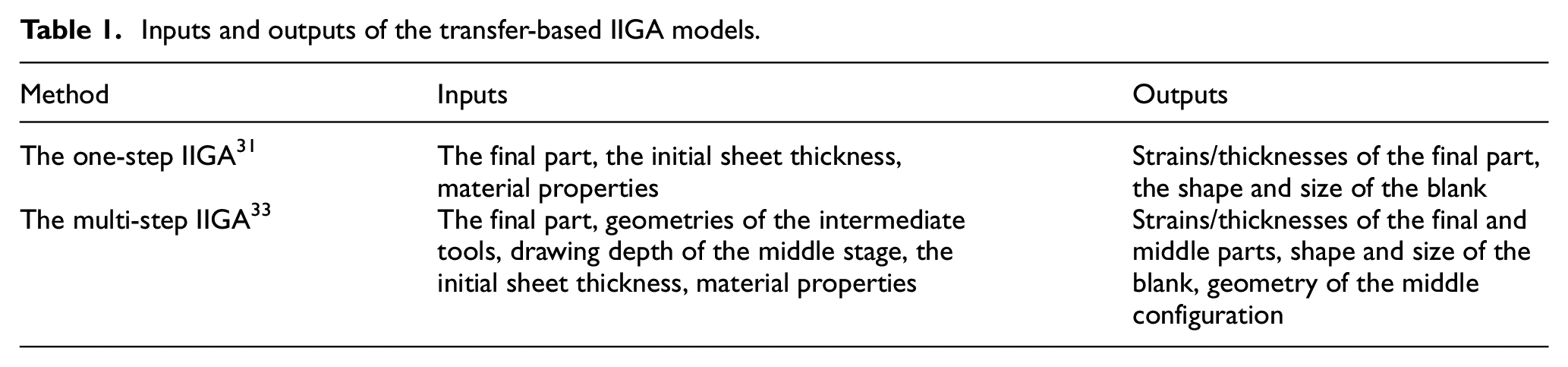
Transfer-based one-step and multi-step IIGA models, which are schematically shown in Figure 1, were presented to analyze SMFP31,33 with acceptable accuracy at a low computation time. The inputs and outputs of these methods are given in Table 1. These NURBS-based methods deal with the minimization of potential energy, deformation theory of plasticity, and considering isogeometric membrane elements.31,33 In these methods, the problem is initially solved by considering elastic conditions, and in the next iterations, plastic properties are added into the computation up to the convergence.
Inputs and outputs of the transfer-based IIGA models.
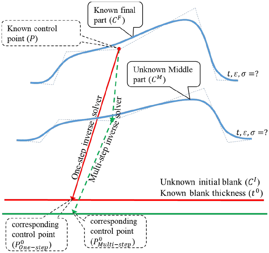
Description of the transfer-based one-step and multi-step IIGA models.
The transfer-based multi-step IIGA model 33 was presented to improve the accuracy of the one-step model in simulations of forming processes that require several forming operations or severe deformation. In these cases, applying the deformation theory of plasticity in several stages and considering information of the middle tools are the main reasons for accuracy enhancement in the multi-step model. This approach is mainly used for analysis of multi-stage forming processes. However, it can be employed to enhance the accuracy of the one-step model in analysis of one-step forming processes.
The aim of this research is far beyond formability analysis of the formed parts with the given geometric parameters. In fact, the objective is to optimally design the geometric parameters of SMFP, by minimizing several objective functions. For this purpose, the one-step and multi-step IIGA models31,33 are utilized to calculate the objective/constraint functions in each optimization loop.
The isogeometric-based framework to optimize SMFP
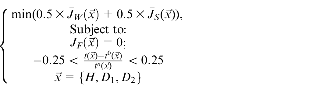
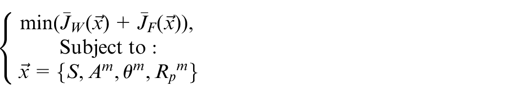
This section aims at presenting an isogeometric-based procedure to design geometric parameters of stamping processes which result in the desired quality of the formed part. This problem can be mathematically stated as the following general form:
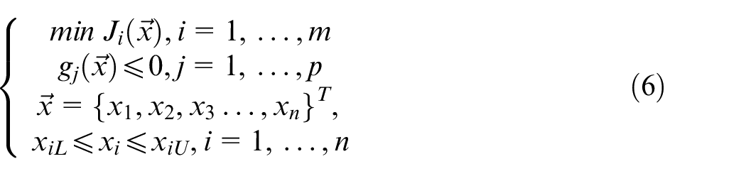
In which,
Objective functions
Among the most important criteria to assess the quality of sheet metal panels, thickness variation, fracture, wrinkling, and stretching are selected in this research.
Thickness variation
In SMFP, thickness variation is a significantly important factor which causes defects in the formed parts. To control this factor, the following function can be minimized 9 :
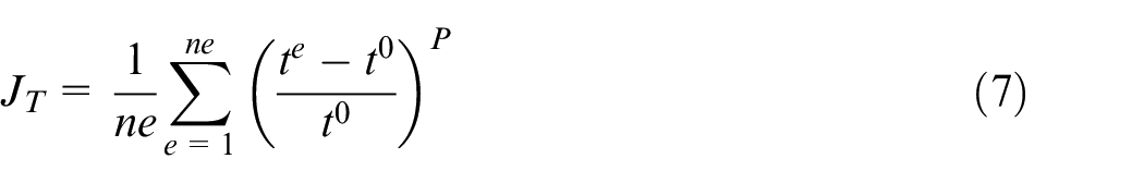
Where,
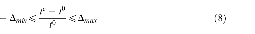
In which,
Fracture and wrinkling
The risk of fracture and wrinkling during the forming process can be evaluated by situating the principal strains on the forming limit diagram (FLD). 35 In this diagram, shown in Figure 2, the fracture or wrinkling problems may occur if the principal strains are located above the forming limit curve or below the wrinkling curve. To minimize these defects, the following functions are defined:
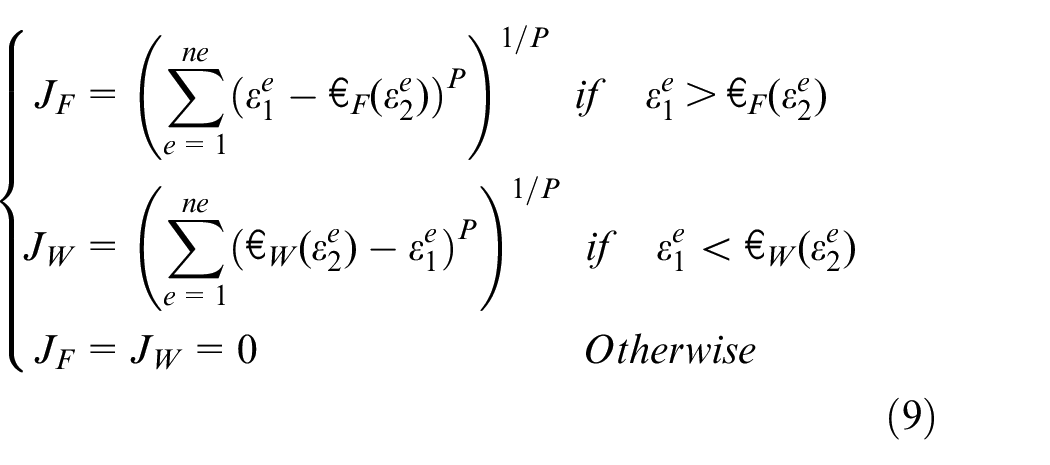
In which,
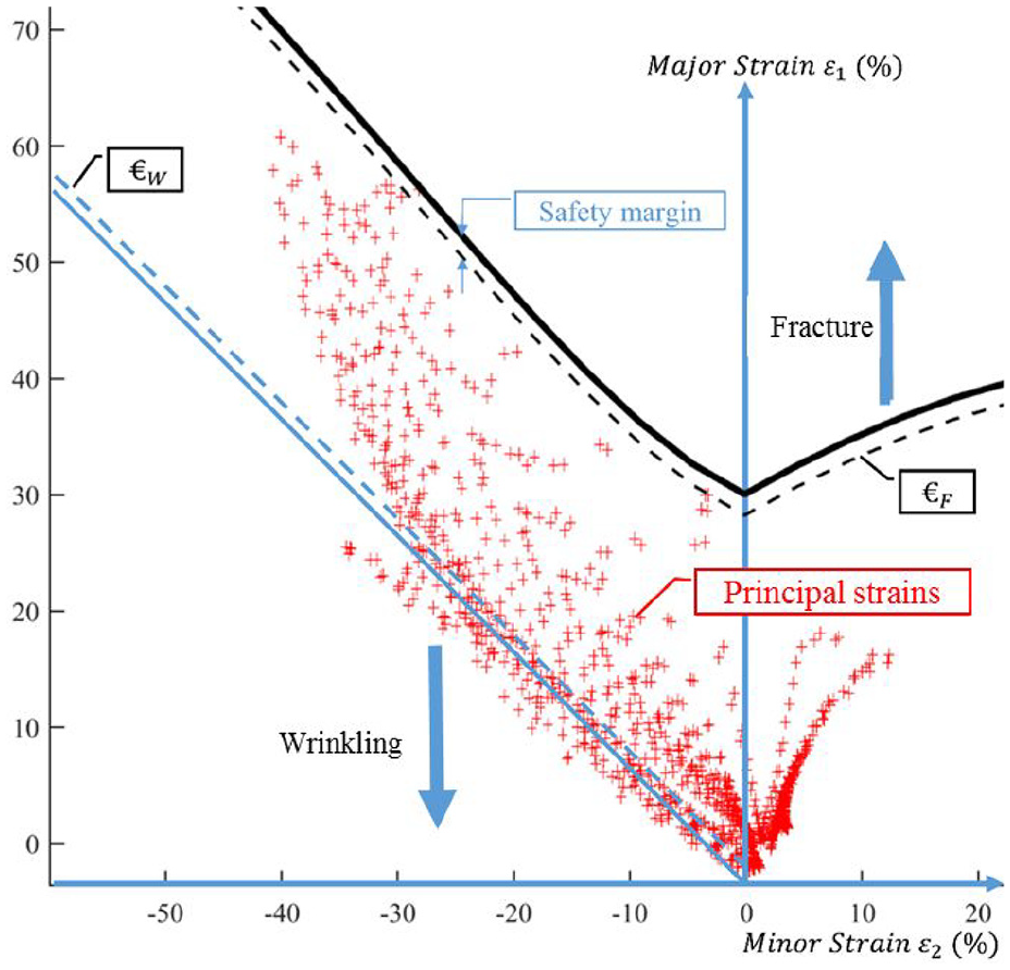
Illustration of principal strains on the FLD.
Stretching
Inadequate stretch of the formed part is an important concern which decreases the dent resistance of the part. 36 To reduce this problem, effective plastic strain in each element should be greater than a specific value. Mathematically, the following function is defined to minimize insufficient stretching of the formed part12,13,15:
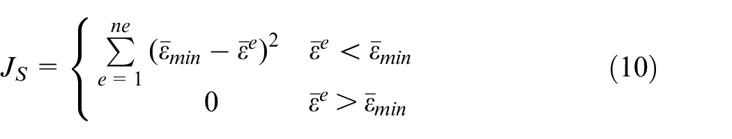
Where,
Design variables
As stated earlier, geometric parameters of addendum surfaces and the middle tools are considered as design variables in this study.
Addendum surface parameters
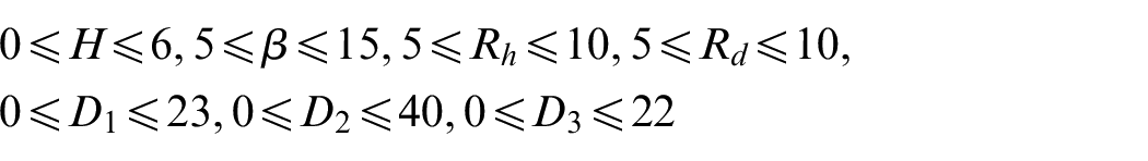
Figure 3(a) shows a part manufactured by a forming process. In this part, addendum surfaces, which will be cut after the forming process, include the protection wall, die profile radius, and blank-holder surfaces. Figure 3(b) displays an addendum profile curve. Considering the parameters
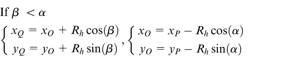
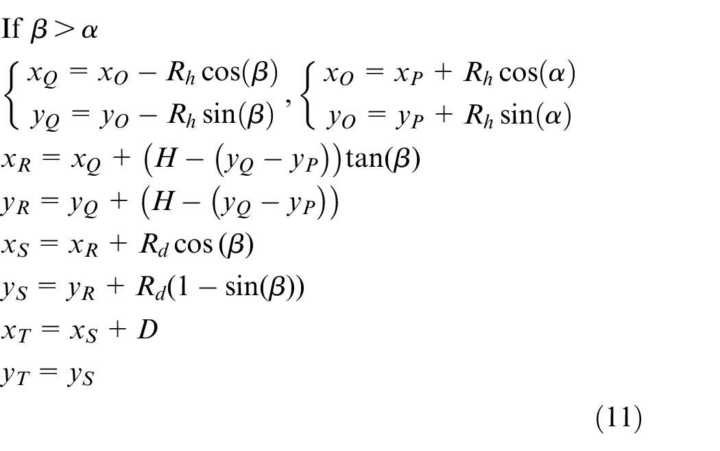
The above equations are solved in each optimization loop for all points located on the trim line, and therefore the entire part is updated for the next step.
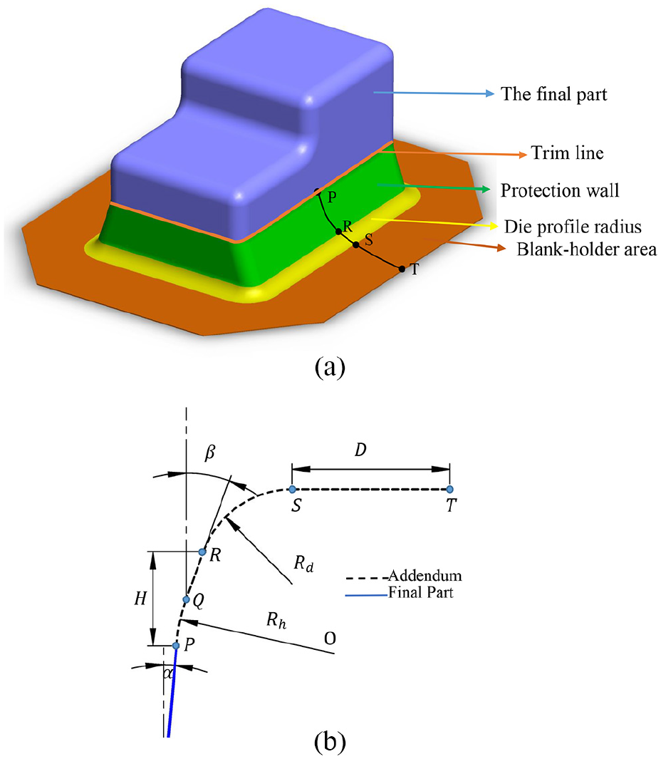
(a) A final part and its addendum surfaces and(b) the addendum profile curve.
The middle tools’ parameters
The quality of the formed parts is affected by varying the middle tools of SMFP. In this research, the shape and size of the tools, their angles, and fillet radii in the middle forming stage are considered as design variables. Also, to limit the variety of design variables, only several standard shapes of tools are taken into consideration.
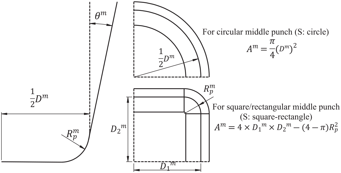
Figure 4 shows the geometric variables of the middle tools in the two-stage forming of a square box. Considering the design variables
The geometric variables of the middle tools.
The relationship between physical and control points
In the previous sections, locations of physical points which are connected to the addendum surfaces and middle parts are computed in terms of design variables
Where,
Solving procedure
Figure 5 shows the sequences of the presented isogeometric-based framework to optimize SMFP. In this framework, locations of physical and control points in each optimization loop are calculated, according to the selected design variables. In the subsequent steps, the IIGA solvers are employed for formability analysis of the part, and therefore the objective functions and constraints are obtained. Eventually, design variables are updated, and the process is repeated until the GA 37 converges.
Flow diagram of the present framework.
Results and discussions
To evaluate the credibility of the presented framework, this approach is initially applied to design addendum parameters of a rectangular box formed in one operation. Next, geometric parameters of the middle tools in a two-stage drawing of a square box are designed so that the desired quality of the final part can be obtained.
Problem 1: Addendum design of a rectangular box
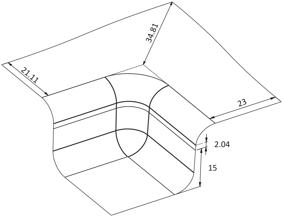
The purpose of this problem is to design addendum parameters of a rectangular box shown in Figure 6(a) with considering the following objective and constraint functions:
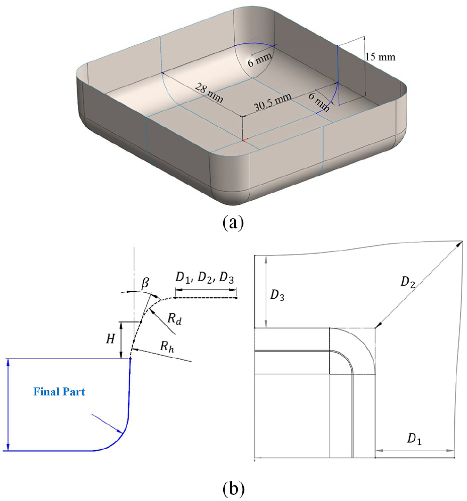
(a)The final part in problem 1 and (b) addendum parameters in problem 1.
With
In which,
Validation and selection of the forming solver
Before using the one-step and multi-step IIGA models31,33 in the optimization process, the performance of these methods is evaluated in formability analysis of the final part with considering different addendum surfaces. To do so, the results of IIGA models are compared to those of forward FEM and experiment.
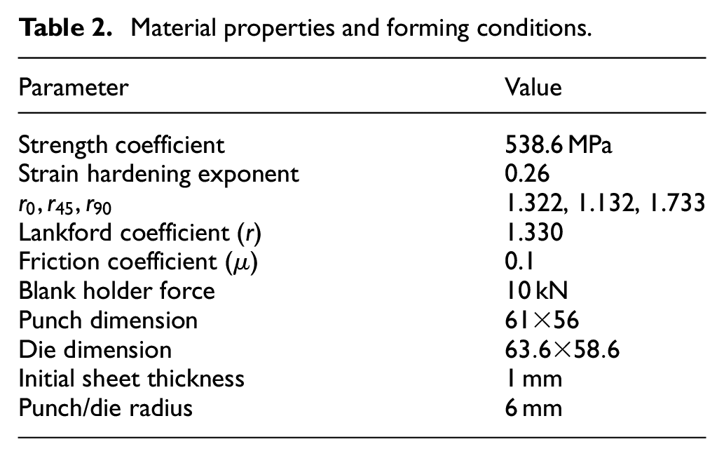
To obtain experimental results, three square blanks with dimensions of
Material properties and forming conditions.
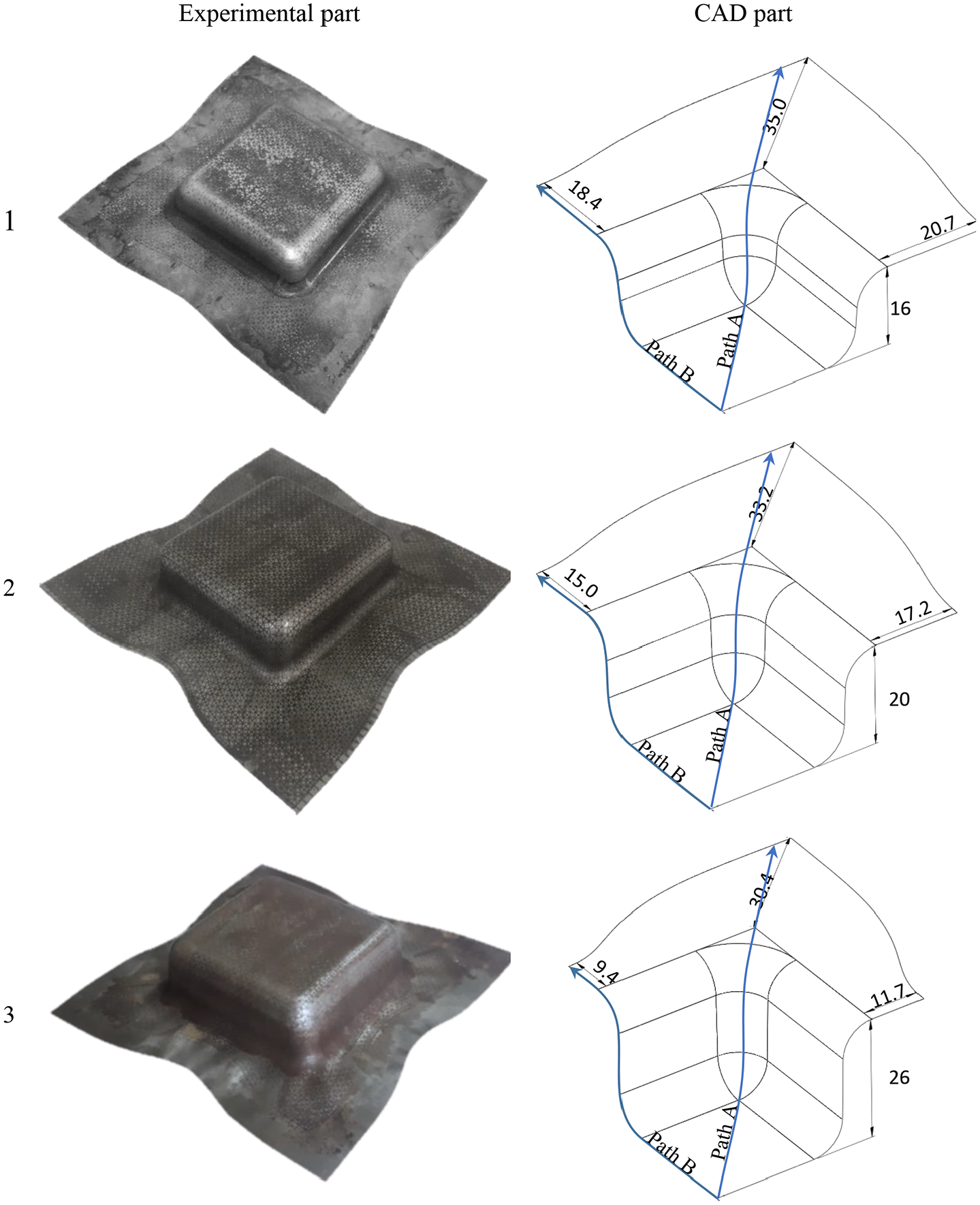
The parts obtained by experiments (dimensions in mm).
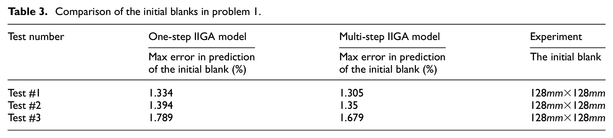
Table 3 compares the initial blanks resulted from the one-step IIGA, multi-step IIGA, and experiments. As revealed in this table, the blanks are predicted with acceptable accuracy in the IIGA models. Also, thicknesses along paths A and B, shown in Figure 7, for all approaches are presented in Figure 8. In the experimental approach, thicknesses of the final parts along these paths were measured by a micrometer after cutting the parts. These paths are selected because the minimum and maximum thicknesses of the entire part are located along paths A and B. Compared to the experimental results, the maximum errors in predictions of minimum and maximum thicknesses are approximately 8.39%, 8.42% for one-step IIGA, 7.99%, 7.23% for multi-step IIGA, and 3.74%, 2.54% for forward FEM. Comparisons of results disclose that forward FEM predicts more accurate results than IIGA models. Also, IIGA models predict thicknesses of the final parts with acceptable accuracy. The solution time for solving these tests using forward FEM and the multi-step IIGA model is around 40 and six times greater than the time needed in the one-step model. Thus, the one-step IIGA solver is selected to optimally design addendum surfaces in this problem.
Comparison of the initial blanks in problem 1.
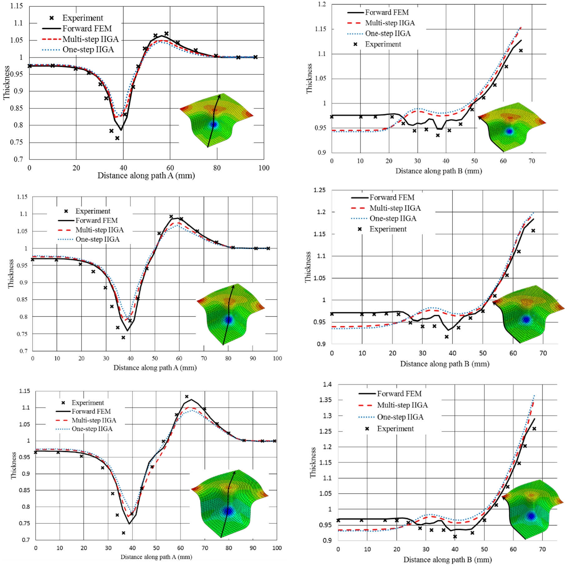
Comparison of thickness distribution along paths A and B in the studied tests in problem 1.
Solving the optimization problem
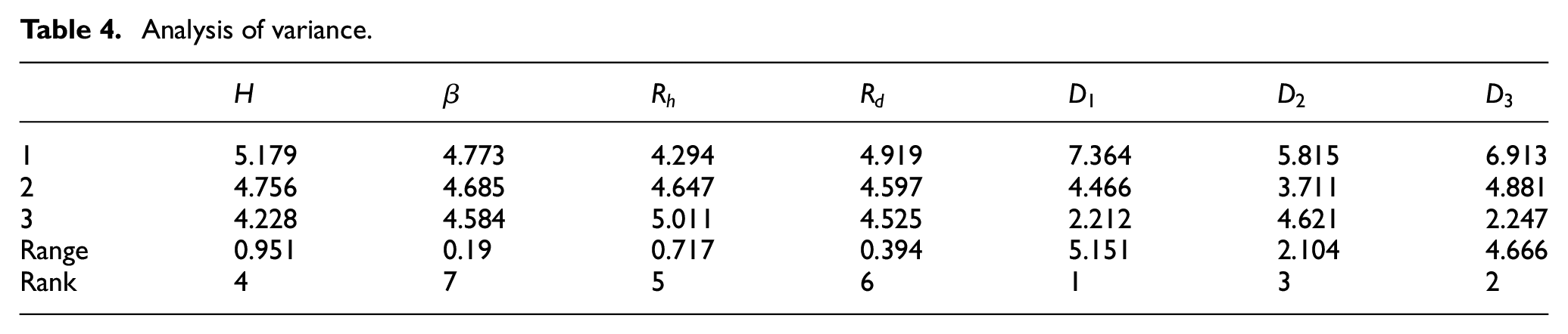
After verification and selection of the forming solver, the most effective addendum parameters should be specified. To study how the considered addendum parameters can affect the objective function, analysis of variance was conducted. To do so, the Taguchi test
38
plan with 27 orthogonal arrays (L27) was employed in which seven parameters at three levels (1, 2, and 3) were considered. In the Taguchi test plan, levels 1, 2, and 3 of a parameter indicate minimum, average, and maximum values of this parameter in the studied domain. In all 27 tests, the whole parts consisting of the final part and addendum surfaces were generated and then imported into the one-step IIGA model. In the Taguchi test plan, the importance of each parameter is evaluated by the signal-to-noise ratio (

Analysis of variance.
Where,
Therefore,
With

The above optimization problem was solved using the presented framework. The calculated optimum answer is shown in Figure 9.
The final part with optimum addendum surfaces (dimensions in mm).
In this research, using the fast IIGA solvers, which remove the gap between modeling and analysis representations, makes it possible to optimally design geometric parameters of SMFP with acceptable accuracy at low computation time. Table 5 presents the required CPU time to calculate the optimum answer with an Intel® CoreTM i7-3632QMCPU, using two different initial populations in the GA. 37 Obviously, the solution time for solving this optimization problem exponentially increases if FEM-based and/or incremental-based methods are used as the forming solver of the GA.
The required time to achieve the optimum answer in problem 1.
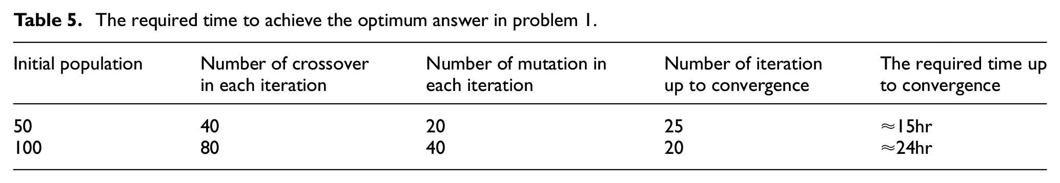
Figure 10 displays the principal strains calculated by the one-step IIGA model on the FLD for the calculated optimum addendum surface and two other addendum surfaces, which lead to unsuitable wrinkling and stretching conditions. This figure shows that the major improvements in the quality of the final part are obtained by considering the optimum addendum parameters, compared to the others. In Figure 10(a), it is demonstrated that the wrinkling problem is significantly reduced by selecting appropriate addendum surfaces. Moreover, as displayed in Figure 10(b), the equivalent strains of 610 elements are smaller than 0.03 in case of considering inappropriate addendum parameters. This number is noticeably decreased in the optimum case (71 elements), and therefore the insufficient stretching problem is meaningfully reduced. Thus, the appropriate design of addendum surfaces improves the quality of the part significantly.
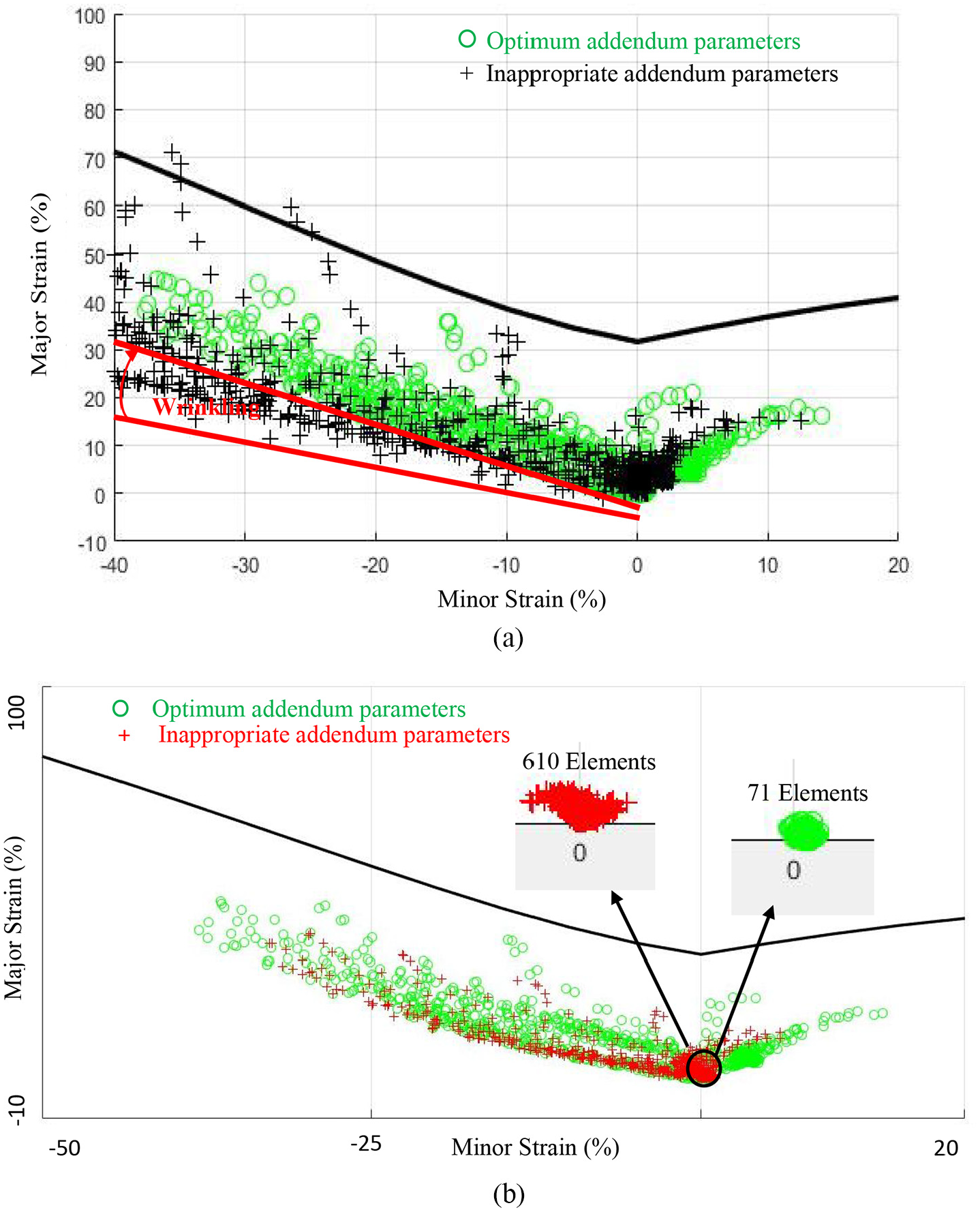
Illustration of the principal strains on the FLD for the final part with different addendum surfaces: (a) improvement of the wrinkling problem and (b) improvement of the insufficient stretching problem.
Figure 11 compares the required blanks to form the optimum part and the final parts with minimum and maximum addendum parameters. As revealed in this figure, the material consumption is decreased in the optimum case, compared to the upper bound of addendum parameters. Therefore, optimum design of addendum surfaces not only can enhance the quality of the part, but also can save the material-consuming.
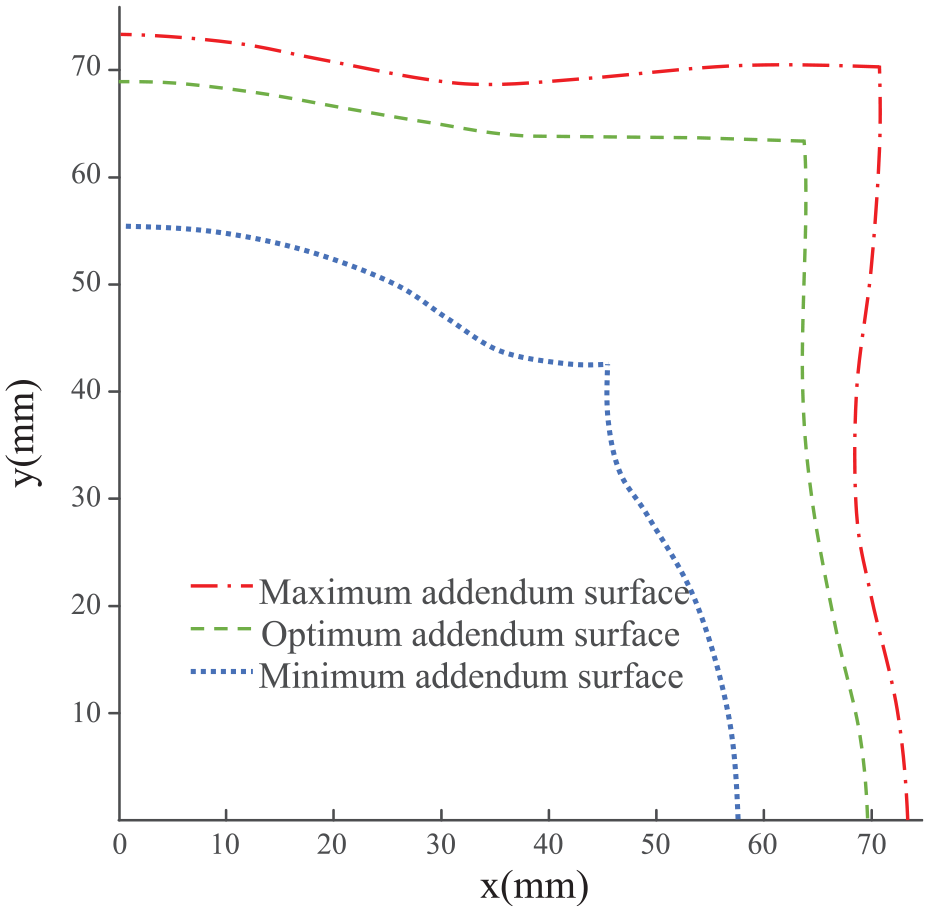
Comparison of the initial blanks required to form the final part with considering different addendum surfaces.
Problem 2: Design of the middle tools in two-stage forming of a square box
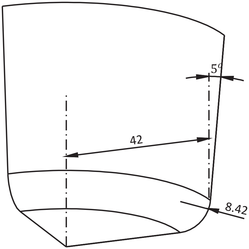
In this problem, optimum geometric parameters of the middle tools in two-stage drawing of a square box depicted in Figure 12 are designed with considering the following objective function:
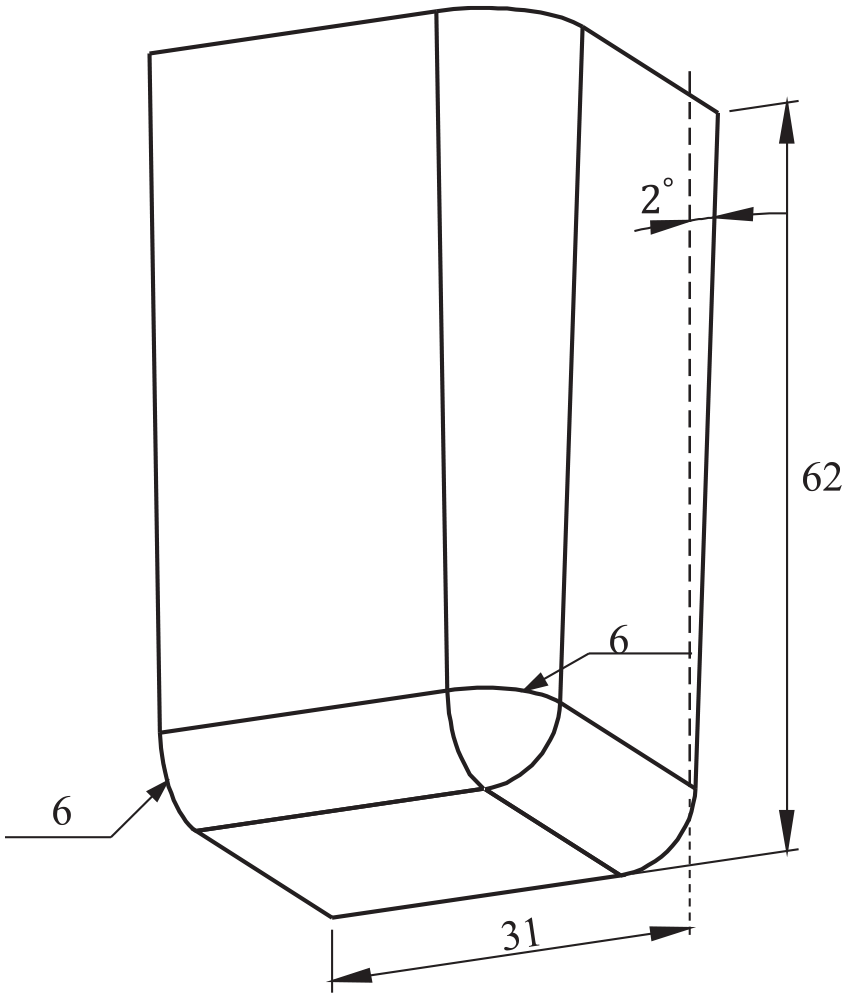
A quarter of the final part in problem 2 (dimensions in mm).
With
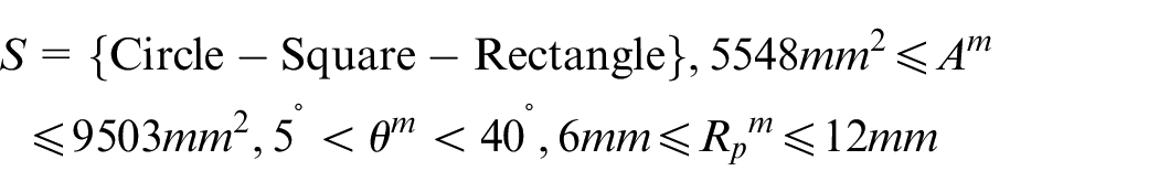
In which,
Geometric parameters of the middle punch.
Validation and selection of the forming solver
The results of forward FEM, IIGA methods, and suggestion of the sheet metal forming handbook 39 indicate that it is impossible to form this square part in one operation. Therefore, the multi-step IIGA model 33 should be employed as the forming solver of the optimization procedure.
Prior to using this solver, the credibility of this method was evaluated in sheet metal forming analysis of the final part drawn in two operations with different middle tools. For this purpose, two-stage forming analysis of the square part with two different middle tools was carried out using the multi-step IIGA and forward FEM. The middle tools utilized in these tests are shown in Figure 14. Considering the middle tools of the tests, the multi-step IIGA solver was initially used for formability analysis of the final part. The blanks obtained by this method are shown in Figure 15. These blanks as well as the considered middle tools of each test were imported into the forward FEM and incremental analysis of these tests was conducted. The final parts resulted from forward FEM and multi-step IIGA are compared in Figure 16. As depicted in this figure, the maximum deviation in prediction of the final parts obtained by forward FEM and multi-step IIGA is approximately 1.56 and 4.4 mm. This amount of error is acceptable, due to the dimensions of the final part. Thicknesses along the diagonal path of the final parts in these tests are presented in Figure 17. The similar trend and acceptable consistency are observed in both approaches. Although forward finite element analysis of these severe forming processes leads to more accurate results, the optimum design of middle tools using this approach requires tremendous computation time and powerful computers. In contrast to forward FEM, the multi-step IIGA rapidly predicts the objective function with acceptable accuracy. 33 Therefore, the multi-step IIGA model is selected to optimally design the middle tools in this problem.
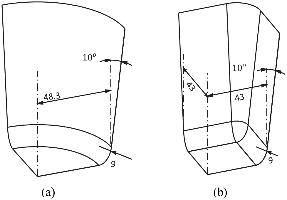
A quarter of the middle tools utilized in the verification tests of problem 2: (a) the circular middle punch of test 1 and (b) the square middle punch of test 2 (dimensions in mm).
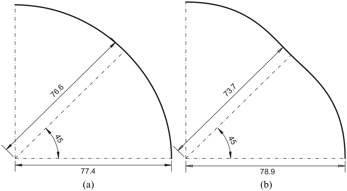
A quarter of the initial blanks obtained by multi-step IIGA in the verification tests of problem 2: (a) test 1 and (b) test 2.
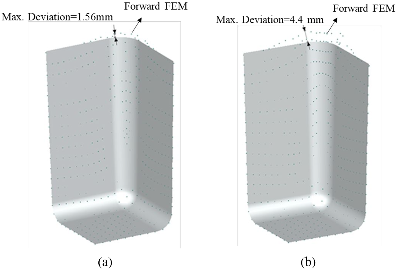
Comparison of the final parts obtained by forward FEM and multi-step IIGA (a quarter of the actual parts is demonstrated): (a) test 1 and (b) test 2.
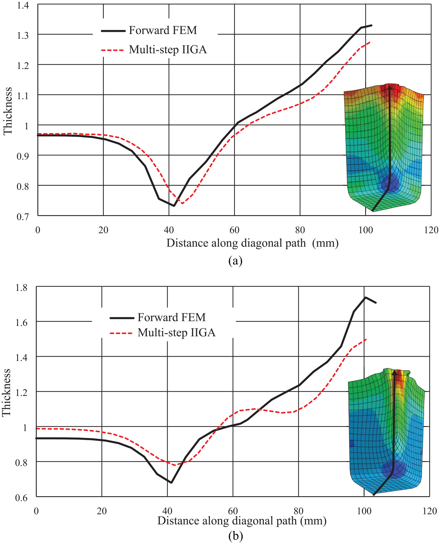
Comparison of thicknesses along the diagonal path of the final parts in the verification tests of problem 2: (a) test 1 and (b) test 2.
Solving the optimization problem
After verification of the multi-step IIGA solver, the optimization problem was solved using the algorithm described in Figure 5. The optimum middle part resulted from this process is displayed in Figure 18. This figure reveals that the best choice for the middle punch shape is the circular one. This is exactly the middle punch shape suggested in the sheet metal forming handbook 39 for deep drawing of a square box.
The optimum middle punch resulted from the presented framework (dimensions in mm, a quarter of the actual part is demonstrated).
In Figure 19, the principal strains obtained by the multi-step IIGA model in case of using different middle tools are displayed on FLD. The considered middle tools include the optimum answer and the circular/rectangular middle tools which result in the unsuitable quality of the final part. This figure shows that the optimum design of middle tools decreases the wrinkling and fracture problems. To illustrate the effects of the middle tools on the wrinkling reduction of the final part, the parts obtained by forward FEM are shown and compared in Figure 20 for two different cases, (a) employing the optimum middle punch (Figure 18) calculated by the developed procedure and (b) using the circular middle punch (
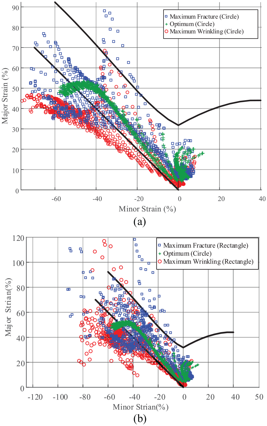
Illustration of the forming severity of the final part with considering different middle tools: (a) optimum middle tools and circular middle tools which result in inappropriate quality and (b) optimum middle tools and rectangular middle tools which result in inappropriate quality.
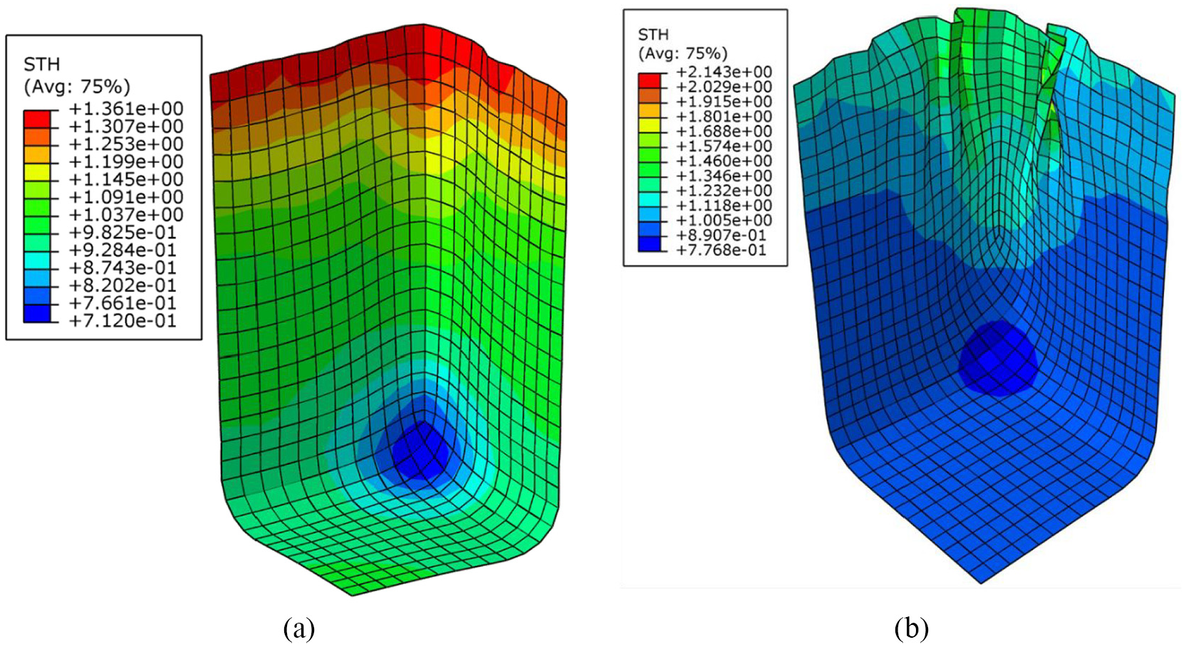
The final parts resulted from forward FEM with considering two different middle tools: (a) the calculated optimum middle tools and (b) the circular middle tools which lead to improper wrinkling condition.
Conclusion
In this study, the IGA-based optimization framework was developed to integrate modeling, analysis, and optimization steps of the simulations using the NURBS functions. This framework takes advantages of the fast IIGA methods to calculate the objective/constraint functions of the genetic global optimization method. Using the IGA-based approach makes it possible to simultaneously observe the effects of changing geometric parameters of the forming processes on the quality of the final parts. The presented optimization procedure was successfully applied to optimally design addendum surfaces of the rectangular box and middle tools of the square box formed in two operations. The results of the optimization process disclose that the wrinkling, fracture, insufficient stretching defects of the formed parts are meaningfully decreased by the appropriate design of addendum surfaces, and middle tools. In addition, rapid optimum design of the SMFP with acceptable accuracy is achieved using the developed IGA-based procedure.
Footnotes
Declaration of conflicting interests
The author(s) declared no potential conflicts of interest with respect to the research, authorship, and/or publication of this article.
Funding
The author(s) disclosed receipt of the following financial support for the research, authorship, and/or publication of this article: The author would like to acknowledge the financial support of Iran National Science Foundation (INSF).