
Abstract
This manuscript discusses the experimental results on 300 W picosecond laser machining of aerospace-grade nickel superalloy. The effect of the laser’s energetic and beam scanning parameters on the machining performance has been studied in detail. The machining performance has been investigated in terms of surface roughness, sub-surface thermal damage, and material removal rate. At optimal process conditions, a picosecond laser with an average power output of 300 W can be used to achieve a material removal rate (MRR) of ∼140 mm3/min, with thermal damage less than 20 µm. Shorter laser pulse widths increase the material removal rate and reduce the resultant surface roughness. High scanning speeds improve the picosecond laser machining performance. Edge wall taper of ∼10° was observed over all the picosecond laser machined slots. The investigation demonstrates that high-power picosecond lasers can be used for the macro-machining of industrial components at an acceptable speed and quality.
Introduction
Hot sections of modern aero-engines like turbine blades and nozzle guide vanes are predominantly made up of nickel-based superalloys, due to their high-temperature fatigue and creep properties. Subtractive machining of this material is paramount to exploit its enhanced properties for various applications. The subtractive material processing requirements of a high-value manufacturing component can be broadly categorized into cutting, drilling, and blind machining processes (e.g. machining of slots).
Cutting and drilling of aerospace nickel alloys is currently performed predominantly using continuous-wave 1 lasers and millisecond pulse duration2,3 lasers respectively. The machining of blind slots is performed predominantly using the electrical discharge machining (EDM) 4 process, although a few researchers have demonstrated the possibility of using short5,6 and ultra-short 7 pulse lasers for machining of advanced materials like nickel alloys.
Of all the subtractive machining process (from mechanical tooling to EDM), laser machining using picosecond lasers 8 is gaining more attention due to its advantages such as; high machining quality, flexibility, and scalability, specifically for processing of advanced materials, most of which are not compatible with other subtractive manufacturing processes.
Esmail et al. 9 employed a 50 W laser source working at a pulse duration of 3 ps for blind machining of industrial-grade alumina ceramics and observed a MRR of 10 mm3/min. Zheng et al. 10 used a 40 W picosecond laser for drilling of thermal barrier coated aerospace nickel alloy. Zheng demonstrated the performance of picosecond laser for delamination free hole drilling, however, the cycle time ranges from 6 min to 2 h depending on the laser pulse frequency for drilling of 0.4 mm diameter hole through 1.3 mm thick material. Semaltianos et al. 7 investigated machining of C263 nickel superalloys using a laser operating at 10.4 ps and an average power output of ∼3 W and observed a machining throughput of ∼1000 µm3/s. Gaidys et al. 11 used a 50 W picosecond laser operating at 1064 nm wavelength for machining of a copper cylinder and observed optimal machining performance at 22 W with a removal rate close to 3.5 mm3/min. Zhang et al. 12 used an 8 W picosecond laser operating at 100 kHz to machine C/SiC CMC and showed a cycle time of 3 min to drill a 0.5 mm diameter hole with a depth of 0.78 mm. Similarly, Li et al. 13 used a 10 W picosecond laser operating at 100 kHz to machine SiC-SiC CMC for micro-hole drilling of 0.45 mm hole with a depth of few 100 μm. Haasler and Finger 14 used a high-power picosecond laser operating at 300 W average power for percussion drilling of various materials including stainless steel, aluminum, copper, and nickel with thickness ranging from 0.5 to 4 mm. Haasler’s investigation specifically focused on the heat accumulation effects and concluded that the residual heating effect starts at ∼20 W and the heat accumulation can be positively exploited to increase the material removal rate. Recently Marimuthu et al. 15 used a 300 W average power picosecond laser source for machining of tungsten carbide and noticed a removal rate in the range of 40–45 mm3/min with no noticeable thermal damage.
As discussed, most of the existing research and understanding on picosecond laser subtractive machining of metals/alloys is based on lasers with average power less than 50 W, operating at a fluence level close to the ablation threshold of the material, only with very few exceptions.8,14 High-power picosecond macro-machining of metals and alloys is still in its very early stage, possibly due to the power limitation of these lasers. Over the last few years, researchers have been developing high-power ultra-short pulsed lasers (USPL) with average powers ranging from a few hundred watts to a few kilowatts; nevertheless, the machining characteristics at high-power levels need to be established. This manuscript aims to conduct a scientific investigation on 300 W picosecond laser machining of C263 nickel alloy.
Materials and experimental methods
A C263 nickel alloy substrate with dimensions of 200 mm × 20 mm × 6 mm was used as a test sample. The C263 grade is a standard aerospace alloy used for various high-temperature aero-engine and gas turbine components, such as heat shields.
A Amphos 2301 laser operating with a pulse duration of 0.9–10 ps, average power output of 300 W, and pulse repetition frequency up to 40 MHz was used as the laser source, in addition to a beam manipulation system consisting of a 3-axis linear stage and a 2-axis galvanometer scanner (Scanlab intelliSCAN III 20). The expanded beam of ∼15 mm was focused using a 167 mm telecentric lens to achieve a focus spot size of ∼40 µm. A schematic of the experimental set-up is given in Figure 1(a).
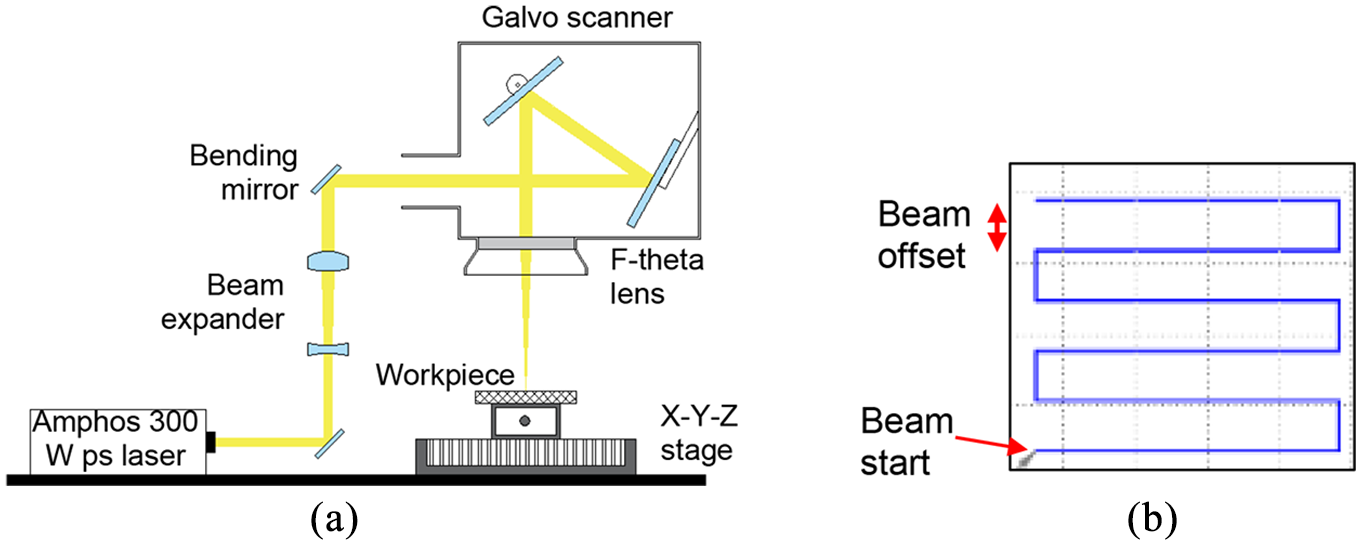
Experimental set-up and the beam scanning pattern: (a) schematic of the experimental set-up and (b) schematic of the beam scanning strategy with a 1D raster pattern.
A rectangular slot of 5 mm width and 10 mm length and machined with various laser parameters. The machining depths vary from tens of micron to 2.5 mm. Figure 1(b) shows the schematic of the 1D continuous raster pattern used in the experimentation. The laser beam is ON from the start to the end of one scanning pass. Experiments were performed in a room temperature air atmosphere (Figure 1(a)) and using a linear raster pattern with a pre-defined offset (Figure 1(b)).
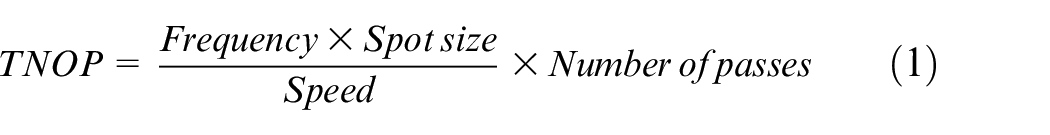
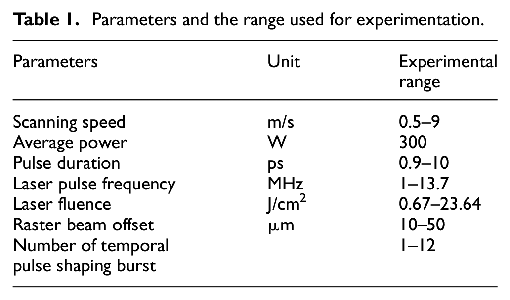
The parameters and the range of values used for the experimentation are given in Table 1. The experiments were performed to investigate the performance of high power picosecond laser for macro machining of nickel alloy and to understand the influence of laser parameters on machining quality and material removal efficacy. To identify the effect of individual laser parameters, an experimental design was adopted whereby one process parameter was varied within its given range (as per Table 1), whilst all other parameters were held constant. The total number of pulses per position (TNoP) was kept constant for each experimental set and was calculated as:
Parameters and the range used for experimentation.
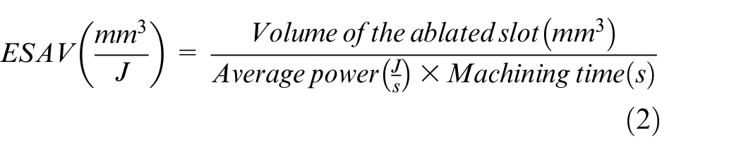
The material removal efficacy has been assessed based on energy-specific-ablation-volume (ESAV) and material removal rate. Energy-specific ablation volume (mm3/J) gives information about the material removal per unit energy and thus can be used to calculate the material removal efficacy independent of laser parameters, and is calculated as follows:
A focus variation microscope (Alicona) was used to measure the surface roughness (Sa) (at the bottom of the slot over an area of ∼5 mm by 5 mm) and geometric features (depth, width, and wall taper of the slot). The laser machined samples were sectioned at the middle of the slot to identify any sub-surface thermal defects. The polished (up to 1 μm grit) and etched (using Kalling’s reagent No.2) samples were analyzed using a Keyence digital microscope (VHX-6000) and Hitachi TM4000 scanning electron microscope.
Results and discussions
Figure 2 shows the influence of laser pulse fluence (from 1.74 to 23.6 J/cm2) on ESAV and material removal rate. All the experiments in Figure 2 were performed at a laser pulse fluence higher than the ablation threshold of C263, which was estimated by Semaltianos et al. 7 to be ∼0.68 J/cm2, at 10 ps pulse duration. As noticed from Figure 2, the increase in fluence reduces the ESAV and MRR (within observed error ranges), and the best material removal characteristics were observed at the lowest investigated laser fluence of 1.74 J/cm2. The reduction in material removal performance at higher laser fluence is related to the change of material removal mechanism from vaporization dominant to melt dominant ablation and can be confirmed based on the cross-sectional microscopic image shown in Figure 3. As seen from Figure 3, a significant recast layer in the range of 60–80 µm was observed for a fluence of 12.12 J/cm2. However, no microstructural changes were observed over the picosecond laser machined slot at a low fluence range (including 1.74 J/cm2).
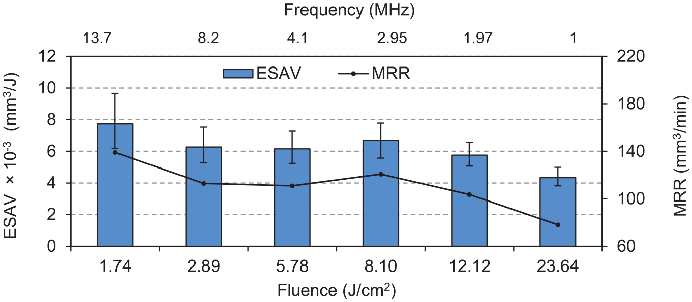
Effect of pulse fluence on ESAV (300 W, 0.9 ps, 20 µm hatch offset, 2400 TNoP, focus @ surface, 2-d scan).
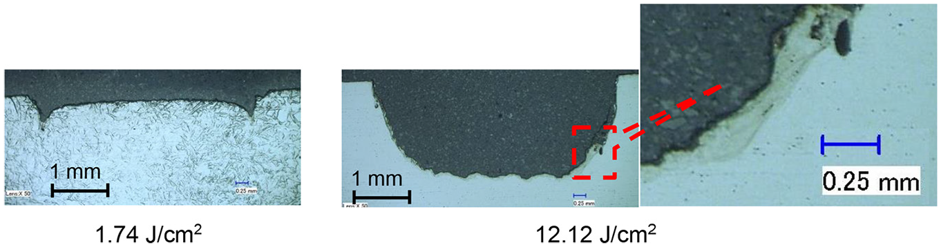
Microstructural characteristic with various fluence on machining performance (300 W, 0.9 ps, 20 µm hatch offset, 2400 TNoP, focus @ surface, 2-d scan).
Shown in Figure 4 is the influence of laser pulse fluence on the machining and surface topological characteristics. As seen from the graph, the machining depth increases with increased laser fluence. The surface roughness shows an exponential increase with an increase in laser fluence till 5.78 J/cm2 and then starts to reduce again. The reduction in surface roughness beyond 5.78 J/cm2 coincides with the reduction in ESAV/MRR and should be related to the melt dominant material removal attributed to the high laser pulse fluence.
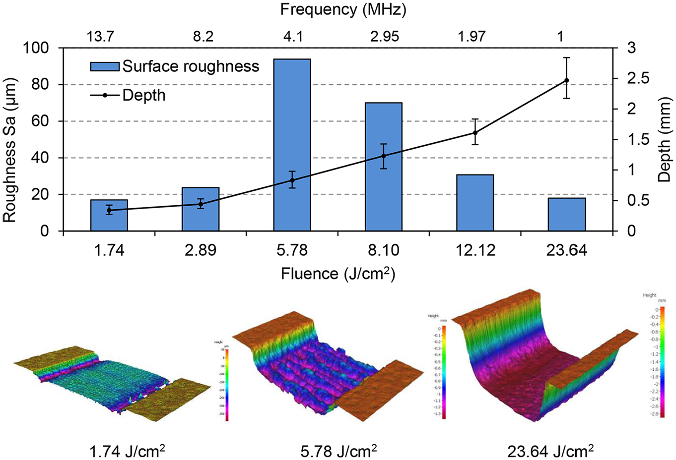
Effect of fluence on machining characteristic (300 W, 0.9 ps, 20 µm hatch offset, 2400 TNoP, focus @ surface, 2-d scan).
The effect of speed at a constant fluence of 1.74 J/cm2, a pulse width of 0.9 ps, and a TNoP of 13,757 is shown in Figure 5. A scanning speed lower than 2 m/s produces insignificant material removal and significantly higher surface roughness. The maximum material removal rate was observed at 2 m/s and the material removal efficiency reduces with an increase in speed. The high surface roughness observed at a speed lower than 2 m/s is attributed to the plasma formation, resulting in heating and melting of the substrate. This can be confirmed based on Figure 6, which shows the cross-sectional micro-structural image for a speed of 0.5 and 9 m/s. In line with the high surface roughness observed in Figure 5, a significantly large recast/melt layer of ∼1.1 mm was observed in Figure 6 for a speed of 0.5 m/s.
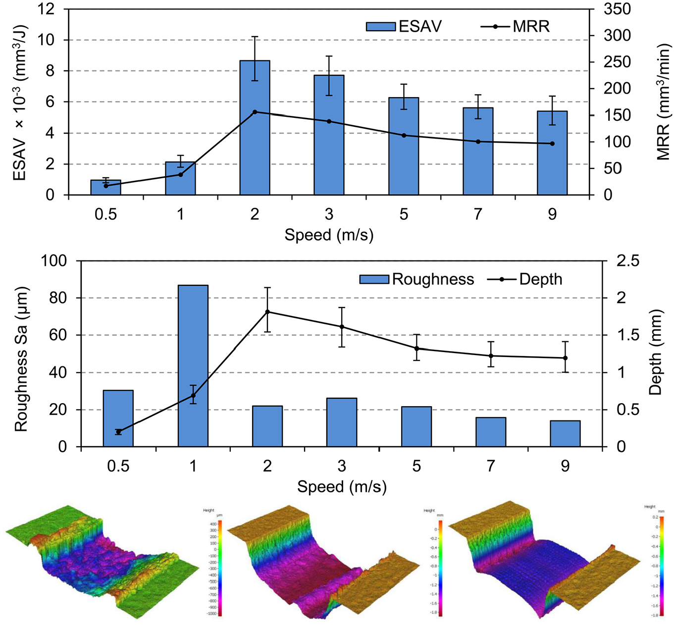
Effect of speed on machining performance (300 W; 1.74 J/cm2; 0.9 ps; 13.75 MHz; 20 µm hatch offset and 12,544 TNoP; focus @ surface; 2-d scan).
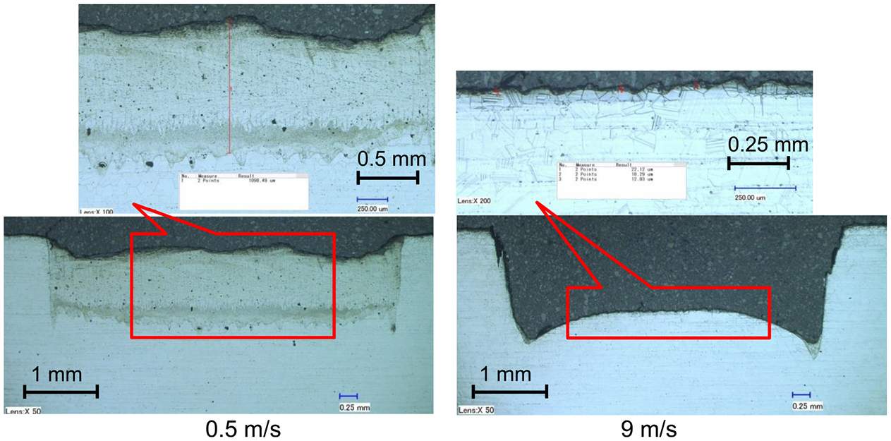
Effect of speed on microstructure (300 W; 1.74 J/cm2; 0.9 ps; 13.75 MHz; 20 µm hatch offset and 12,544 TNoP; focus @ surface; 2-d scan).
These observations suggest that low-speed laser irradiation results in significant melting and solidification, without material removal. Previously, researchers have used ultra-short pulse laser at low speed for machining applications, however they are at significantly lower average power. Above the minimal threshold scanning speed (2 m/s) an increase in speed results in a decrease in surface roughness and a roughness (Sa) of ∼14 µm was observed for a speed of 9 m/s. As can be seen from Figure 6, a recast/heat-affected layer of 10–20 µm was observed over the surface of the slot, machined at a laser scanning speed of 9 m/s.
The influence of pulse width on machining characteristics, with all other parameters, kept constant is shown in Figure 7. As can be noticed from the figure, increased material removal can be achieved when machined with low pulse width. A change in pulse width from 10 to 0.9 ps increased the material removal rate from 90 to 120 mm3/min, which represents a 33% increase in the removal rate. This is directly related to the increase in laser peak power with a decrease in pulse duration. An opposing trend was noticed for surface roughness, with a low surface roughness at low pulse durations irrespective of the higher ablation depth. Increases in pulse duration ultimately reduce the peak intensity and increase the laser interaction time. This laser-material interaction time tends to push the material removal mechanism toward being melt based, and thus machining with small pulse width results in better material removal performance in terms of both removal rate and surface roughness.
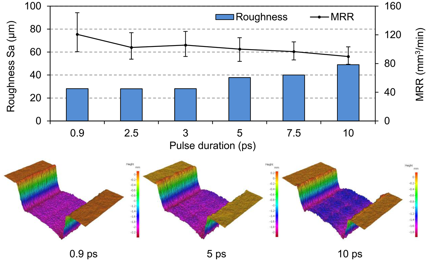
Influence of laser pulse width on machining performance.
The effect of raster hatch offset (distance between the consecutive raster lines; Figure 1(b)) on ESAV, roughness (specifically within the surface area measured), and surface topology is shown in Figure 8. As can be seen, hatch offset has a significant influence on the surface roughness than material removal performance. The material removal performance (i.e. ESAV) is almost similar, with slightly higher performance at 20 µm hatch offset. The roughness is almost uniform for a hatch offset range of 20–40 µm, with significantly higher surface roughness at low (10 µm) and high (50 µm) hatch offsets. As mentioned before the focal position beam size is ∼40 µm and when the hatch offset is higher than the beam size, the material between two consecutive tracks are not fully ablated resulting in higher roughness. High surface roughness at 10 µm hatch offset should be due to the residual heating effect. In general, a hatch offset equal to half the beam size should be ideal in terms of both roughness and material removal rate.
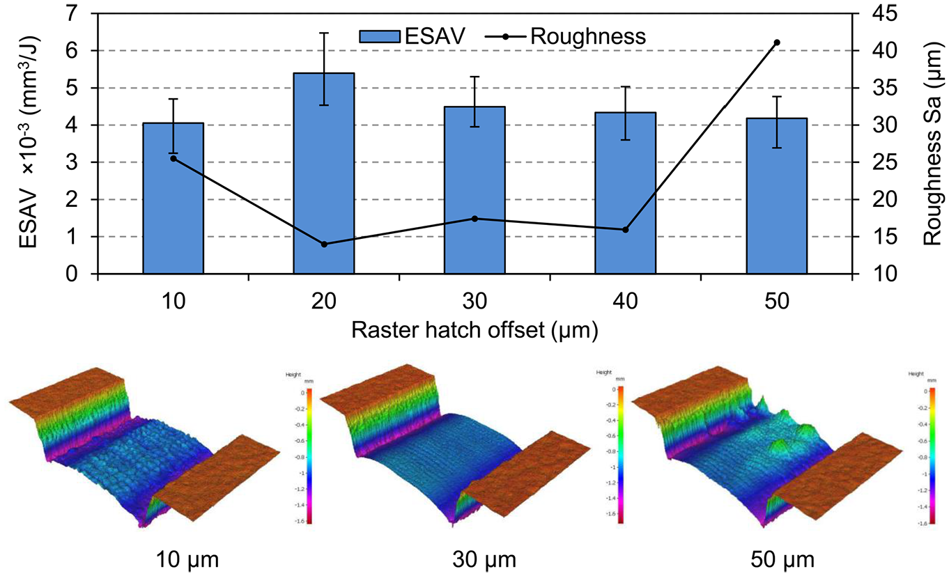
Effect of laser beam raster hatch offset on machining performance.
All the results discussed up to this point used a 2D raster scan pattern as shown in Figure 9(a). It’s expected that the machining strategy in terms of raster scan pattern will significantly influence the machining characteristics and further experiments have been performed to understand 1D and 2D with angle scan pattern, as shown in Figure 9(a), and the results are given in Figure 9(b) and (c).
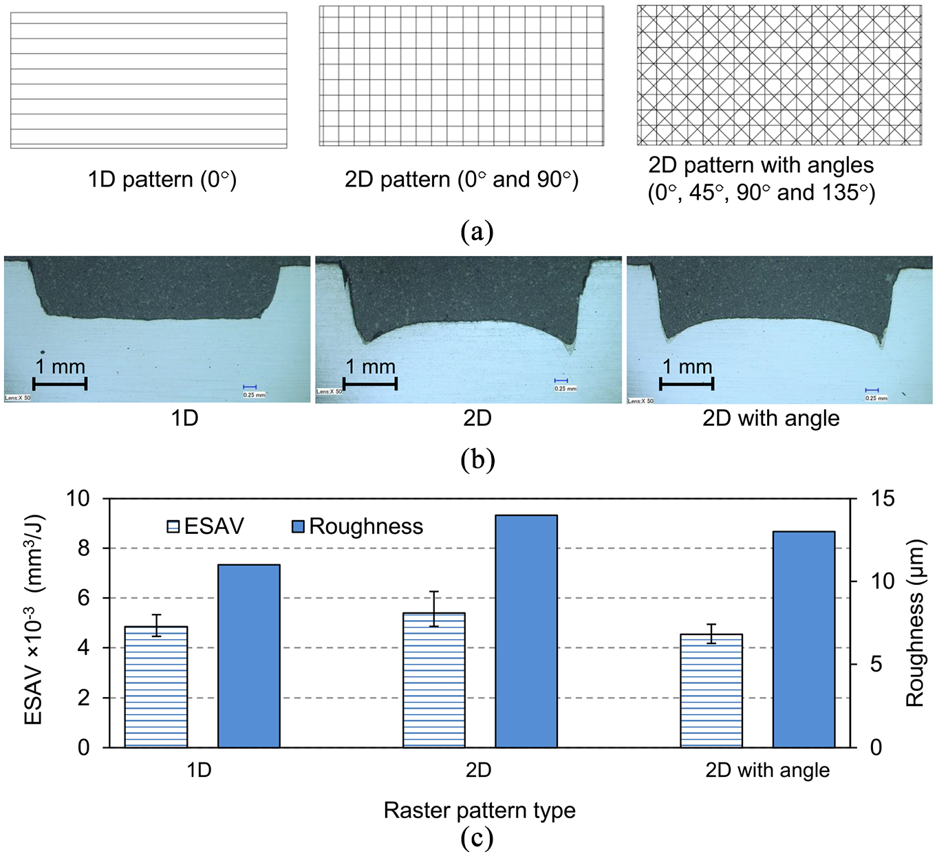
Effect of raster pattern type on ablation characteristics: (a) type of raster patterns, (b) cross-sectional microscopic image for various raster pattern types, and (c) effect of raster pattern type on machining characteristics.
As seen from Figure 9(b), significant edge effects are observed over the samples machined with 2D and 2D with angle pattern, which is likely due to the acceleration and deceleration of the galvanometer scanner over the edge of the sample. Also, as shown in Figure 1(b) the laser beam was ON during the movement from one raster line to the next raster line which negatively influences the machining quality around the edge. This can be addressed by using a scan pattern in which the laser beam is OFF between two consecutive raster lines. In general, the 2D scan pattern resulted in better material removal characteristics, but higher surface roughness. The surface roughness can be addressed by fine-tuning the machining pattern around the edge of samples as discussed above.
The effect of scanning passes (from 10 to 118 passes) on ablation rate and ESAV for a fluence of 1.74 J/cm2 is shown in Figure 10. As noticed, the ablation rate decreases with increases in the number of scanning pass. The rate of decrease in ablation (rate/pass) and ESAV were significant during the first 40 passes (10–40 passes reduce the ablation rate from 70 to 40 µm); this is predominately due to the incubation effect. The linear reduction in ablation rate and ESAV observed after 40 passes are related to the small depth of focus with ultra-short pulse lasers and can be addressed by moving the focal position in line with the ablation depth as shown in Figure 11.
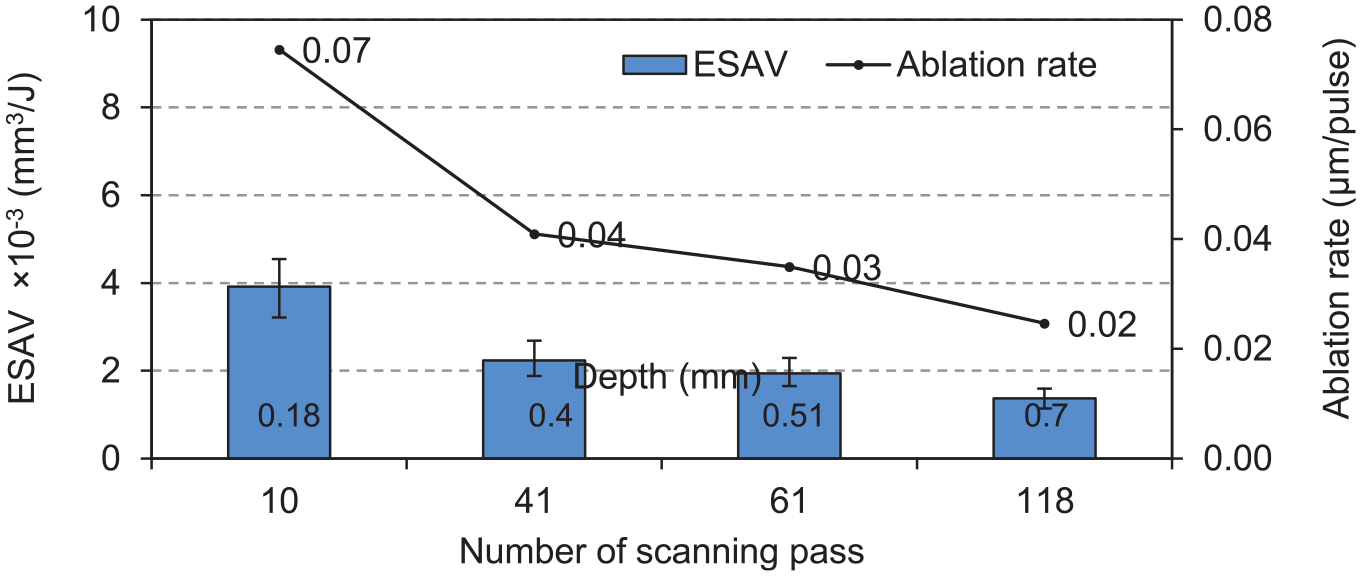
Effect on number of pass on machining characteristics.
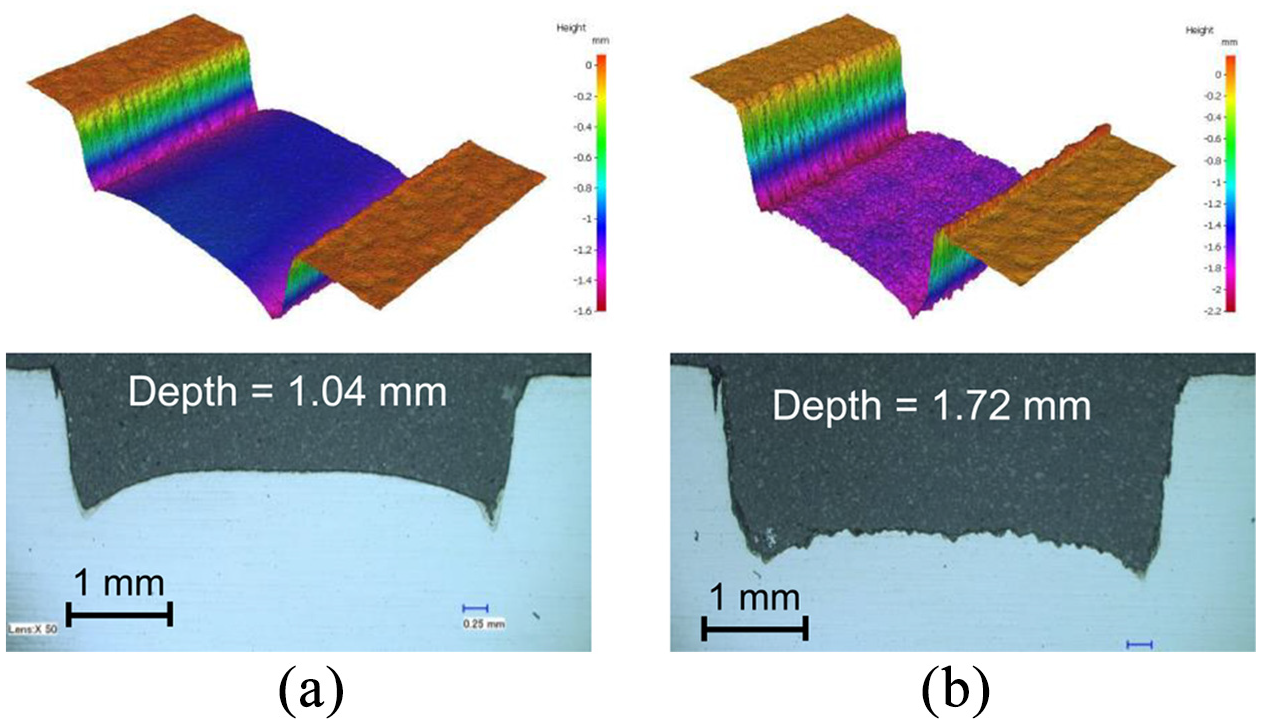
Effect of focal position on ablation characteristics (9 m/s; 13,757 kHz; 0.9 ps; 300 W; 1.74 J/cm2; 12,228 number of pulse per position; 2-d with angular scan; 100 total pass; focus control every 20 pass): (a) without focus control (roughness Sa = 13.3 µm; MRR 81 mm3/min) and (b) with focus control (roughness Sa = 33.9 µm; MRR 127 mm3/min).
Figure 11 shows the effect of ablation characteristics with and without focus control. The focus position was maintained over the slot surface, by moving the beam focus into the material by 0.16 mm every 20 passes. As notched from Figure 11(b), maintaining the laser focus over the surface of the slot increases the machining depth by ∼65%, for a slot of 1.7 mm deep. However, the slots machined with focus control shows significantly higher surface roughness, which is due to the increase in machining depth, and the use of a sub-optimal beam scan strategy (2D pattern with angle-Figure 9(a)).
Temporal pulse separation is an effective method 16 to reduce the laser fluence of each pulse and maintain a reasonable pulse-off period between two consecutive pulse bursts. Figure 12 shows the schematic of the temporal pulse shaping using the pulse burst mechanism. A pulse burst is generated by splitting one pulse into several pulses at a burst frequency of 40 MHz.
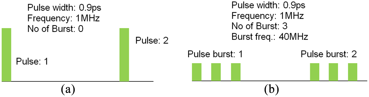
Schematic of the temporal pulse shaping: (a) normal pulse (1 burst) and (b) three burst pulse.
The influence of temporal pulse shaping on laser machining performance is shown in Figure 13. As elucidated low pulse fluence generated using pulse bursts had a significant influence on the machining performance. Increases in pulse separations from one to six, increased the removal rate, ESAV and ablation depth, and reduced the roughness of the machined slot. Use of laser beam fluence significantly higher than the threshold ablation fluence 7 resulted in residual heating and plasma generation which decreased the material removal efficacy. No significant increase in machining performance was observed beyond six pulse separations (i.e. 6–12 number of burst), corresponding to pulse fluence range of 1.35–0.67 J/cm2. This should be attributed to the fact that, for fluence in the range of 1.35–0.67 J/cm2, the ablation rate is predominantly based on the laser average power, which was kept constant at 300 W. A 12 pulse burst with a pulse fluence of 0.67 J/cm2 (same as the ablation threshold 7 of the material) shows best machining performance in terms of both material removal and surface roughness.
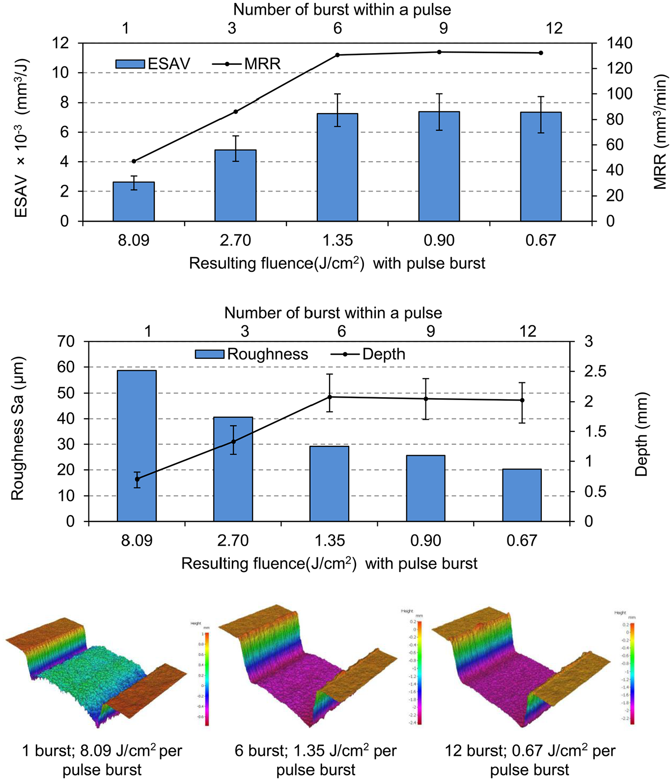
Effect of temporal pulse shaping on machining characteristics.
Figure 14 shows the cross-sectional microstructural image of the C263 slot machined with various pulse separations. In line with the observation from Figure 13, a maximum number of pulse bursts (12) that produce minimal laser pulse fluence (0.67 J/cm2), resulted in better machining performance. As noticed from the high-magnification images of the slot machined with 12 pulse burst (0.67 J/cm2), thermal damage (heat affected zone/recast layer) in the range of 15–25 µm was observed over the surface of the machine slot. No noticeable thermal defects were observed over the wall of the slot, however, an edge taper of ∼10° was observed over the sidewalls of the slot, which needs to be addressed for fully-developed industrial use of high-power picosecond laser.
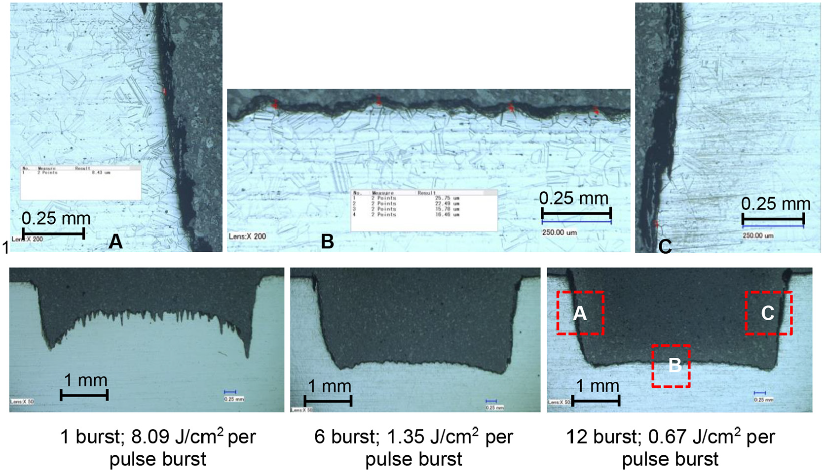
Effect of temporal pulse shaping on machining performance.
Conclusions
An experimental study has been performed to investigate the characteristics of 300 W picosecond laser machining of nickel superalloy. The main conclusions from this investigation are:
At optimal conditions, an average power of 300 W produces a recast layer in the range of 20–30 µm over the surface of the picosecond laser machined slot.
In general low fluence in the range of 0.9–0.6 J/cm2 results in better machining performance, in terms of material removal rate, surface roughness, and recast layer.
High pulse frequency (in the range of 10’s of MHz) corresponding to low fluence and high average power doesn’t negatively impact the machining performance of nickel alloy.
Reduction in laser pulse width (from 10 to 0.9 ps) increases the material removal rate (from 88 to 120 mm3/min) and reduces the surface roughness (from 49 to 28 µm). Change in laser pulse width from 0.9 to 10 ps decreases the energy specific ablation volume from 1.2 × 10⁻³ to 0.8 × 10⁻³ mm3/J.
Within the investigated range of speed (11 m/s), increase in scanning speed (which results in increased pulse to pulse separation) results in better machining performance.
A pulse frequency of 13.75 MHz, and a speed lower than 2 m/s (275 pulse per position) results in significant melting of the substrate with no noticeable material removal, attributed due to plasma formation and heating.
Energy specific ablation volume of 7.4 × 10⁻³ mm3/J and material removal rate of 133 mm3/min was observed at a laser pulse fluence of 0.67 J/cm2 and average picosecond power of 300 W.
High-power picosecond lasers can be used for machining aerospace nickel alloy, with productivity in line with the conventional long pulse subtractive laser processes.
Edge wall taper of ∼10° was observed over all the picosecond laser machined slots.
Footnotes
Declaration of conflicting interests
The author(s) declared no potential conflicts of interest with respect to the research, authorship, and/or publication of this article.
Funding
The author(s) disclosed receipt of the following financial support for the research, authorship, and/or publication of this article: This work was supported by the United Kingdom High-Value Manufacturing Catapult funding under the MTC CRP project 33778-02.