
Abstract
The radial cold rolling process is widely used in industry due to the advantages of chip removing processing. In this study, circular complex profiles were formed by cold-rolling with radial feed, using a patented device with two roller-tools. By achieving several numerical simulations of the radial rolling process, the study aimed to establish the influence that the maximum set force and the diameter of the workpiece have on the productivity of the process and the quality of the formed trapezoidal and metric grooves. The numerical simulations were performed with ABAQUS/Explicit software and by using a previously validated finite element model. The penetration curve of the roller-tools in the material was introduced in the simulation as an analytical function and was determined based on experimental researches. To express the dependency of the penetration curve coefficients on other rolling conditions, a multivariable analysis using a design of experiments technique was performed. The parameters that result from numerical simulations and were analyzed in this study are the profile forming time, the maximum radial force, the distribution of the equivalent strains in the axial section of the profiles, and the profile dimensions. The conclusions that were drawn from the analysis of the results regarding the influence of the set maximum force and the workpiece diameter on the analyzed parameters of the numerical simulations, together with the definition of efficient process criteria, allowed also the identification of the optimal conditions of the rolling process.
Introduction
Cold forming presents major advantages compared to the cutting processes1–6: (i) more productive, (ii) no production of chips, and (iii) high quality of the generated surface. Moreover, because the deformation occurs at ambient temperature, the initial properties of the material are irreversibly changed, forming a continuous fiber in the material of the part, which ensures better mechanical properties,7–9 such as: roughness, micro-hardness, and fatigue resistance.
Radial cold rolling with two roller-tools is increasingly used in industry to obtain parts with complex profiles (threads, grooves, etc.) on revolution pieces, generally for series production,2–6 and are in continuous development and competition concerning the quality and cost of products. The trend is oriented toward developing and implementing numerical modeling which represents a very useful and efficient tool for successful the experimental researches.
The finite element modeling of the cold rolling process started in the 1990s by Rowe et al., 10 but the high volume of calculations and the limited capacity of computers to handle a large amount of data, within a reasonable time, restricted these studies to the understanding of the deformation process. Martin11,12 used finite element analysis based on MARC finite element code and, using a 2D plane strain finite element model, has established an adequate mesh to investigate the residual stress for a thread profile obtained by radial cold rolling. This process was also investigated by Domblesky and Feng through several numerical models and methods implemented in the finite element code DEFORM. First, by using a 2D plane strain finite element model, Domblesky and Feng 13 analyzed the effect of workpiece diameter, friction on thread formation, flow stress, and thread form on material flow and thread profile in external thread rolling of large diameter workpieces. Furthermore, they have developed a three-dimensional numerical model for fat-die thread rolling to incorporate the effects of both groove orientation and workpiece movement in the simulation. 14 Kamouneh et al. 15 investigated the work hardening effect of flat rolling on the critical regions of gear through the use of hardness maps, grain-flow photographs, and finite element models developed in ABAQUS and DEFORM. Also, using numerical simulations, they have optimized the shape and the size of the workpiece, 16 to reduce the negative effects such as the “rabbit ear” phenomenon. Song et al. 17 used numerical simulations to study the influence of process parameters on small threads obtained by rolling. Kowalik and Trzepieciński 18 estimated the deformation force and the influence of friction on the material flow in the rolling process of the longitudinal channels using numerical simulation and MARC software. Kukiełka et al. 19 have developed an application of numerical analysis in the ANSYS program to both determine and analyze the effects of friction coefficient, initial yield stress, and plastic hardening modulus that are used in the numerical simulation of the cold rolling of the external round thread. Cui et al. 20 have investigated the deformation mechanism and have improved the spline shaft performance obtained by axial-infeed incremental rolling by using 3D DEFORM software. Ma et al.21,22 have investigated the gear roll-forming process with axial-infeed using Finite Element Method (FEM) simulations (3D DEFORM software), have developed an analytical model for predicting the pitch error of gear, and also have optimized the geometric design of rolling tool to reduce the deflection and root stress of rolling tool’s teeth, to both eliminate the scratches on tooth flank of the formed gear and to reduce the height of rabbit ear. Kramer and Groche 23 have modeled the thread rolling process using Simufact Forming v13 and have made a systematic study of the influence of the process configuration and the specimen preparation toward the occurrence of defects in rolling processes. Results show that the tribological system influences the rolling process. Yuan et al. 24 have investigated the influence of roller motion on profile and hardness of T2 worm using numerical modeling (software Forge™) and experiments. Zhang et al. 25 have investigated the deformation mechanism in the self-infeed rolling process of thread shaft using DEFORM 3D software, showing the behavior of material flow and material hardening. They also investigated 26 the protrusion generation in the forming process of long threads by axial self-infeed rolling process, establishing that to reduce the protrusion height, the pre-rolling angle should be 20.
In concluding this survey, it may be stated that numerical analysis is a powerful and reliable tool for manufacturing process investigation. The accumulated knowledge has enabled the forming industry to improve process competitiveness, product performance, and service life.
Through numerical simulation in the ABAQUS environment, this paper examines the influence that the maximum set force and diameter of the workpiece have on both the process productivity and the quality of circular profiles obtained by radial cold rolling with a patented device. The elements that are analyzed in the study are the profile forming time, the maximum radial force, the profile dimensions, and the equivalent strains distribution in the axial section of the profiles. Three criteria are defined to evaluate the process efficiency: (i) process productivity, (ii) material hardening, and (iii) profile dimensions.
Experimental work
Processed material and profiles
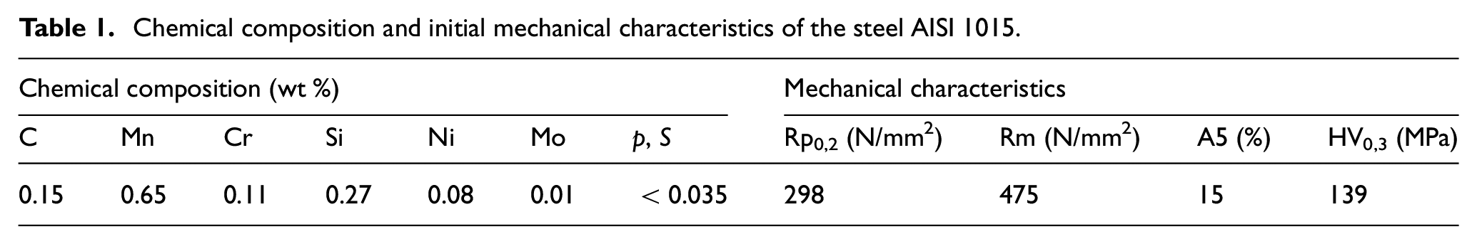
The material used in this investigation was AISI 1015. Its chemical composition and mechanical characteristics are given in Table 1. The workpieces were obtained by turning and grinding from a hot extruded bar.
Chemical composition and initial mechanical characteristics of the steel AISI 1015.
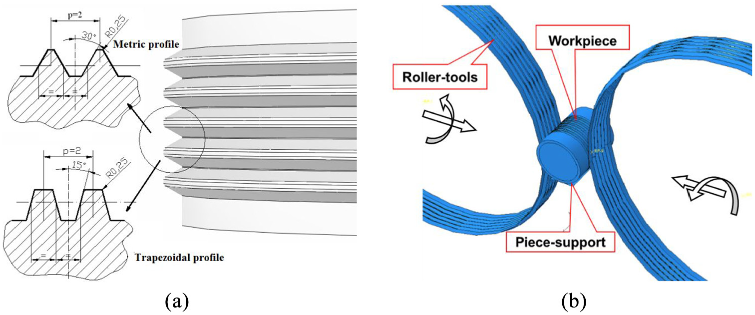
The profiles formed by radial cold rolling using two roller-tools and in-feed method were a concentric channels surface as in Figure 1(a), with five similar grooves in axial section for metric thread M20x2, respectively, for trapezoidal thread Tr20x2. Geometric characteristics of the two types of profiles are shown in Figure 1(b) and (c).
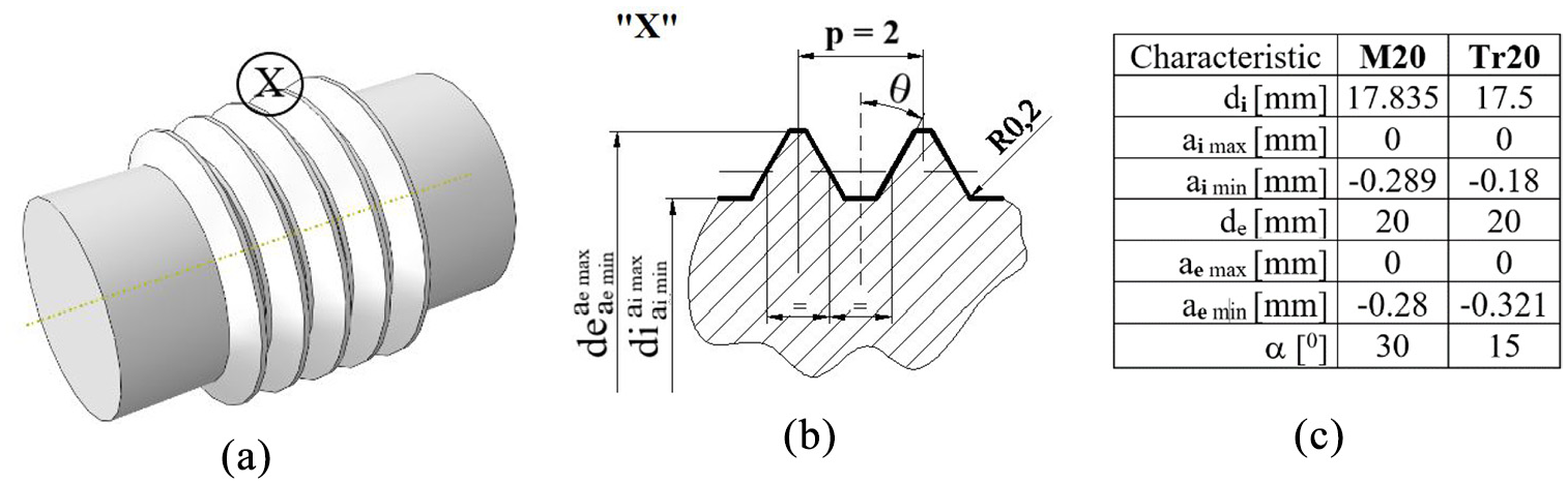
Form of the cold rolling profiles: (a) 3D drawing, (b) X detail, and (c) dimensions and deviations of the two types of profiles.
Experimental system
The radial cold rolling process was performed by applying the kinematic scheme in Figure 2(a) on a lathe using an experimental system represented schematically in Figure 2(b). The patented device, Ungureanu et al., 27 is shown in Figure 2(c) and is described in detail by Iordache et al. 28
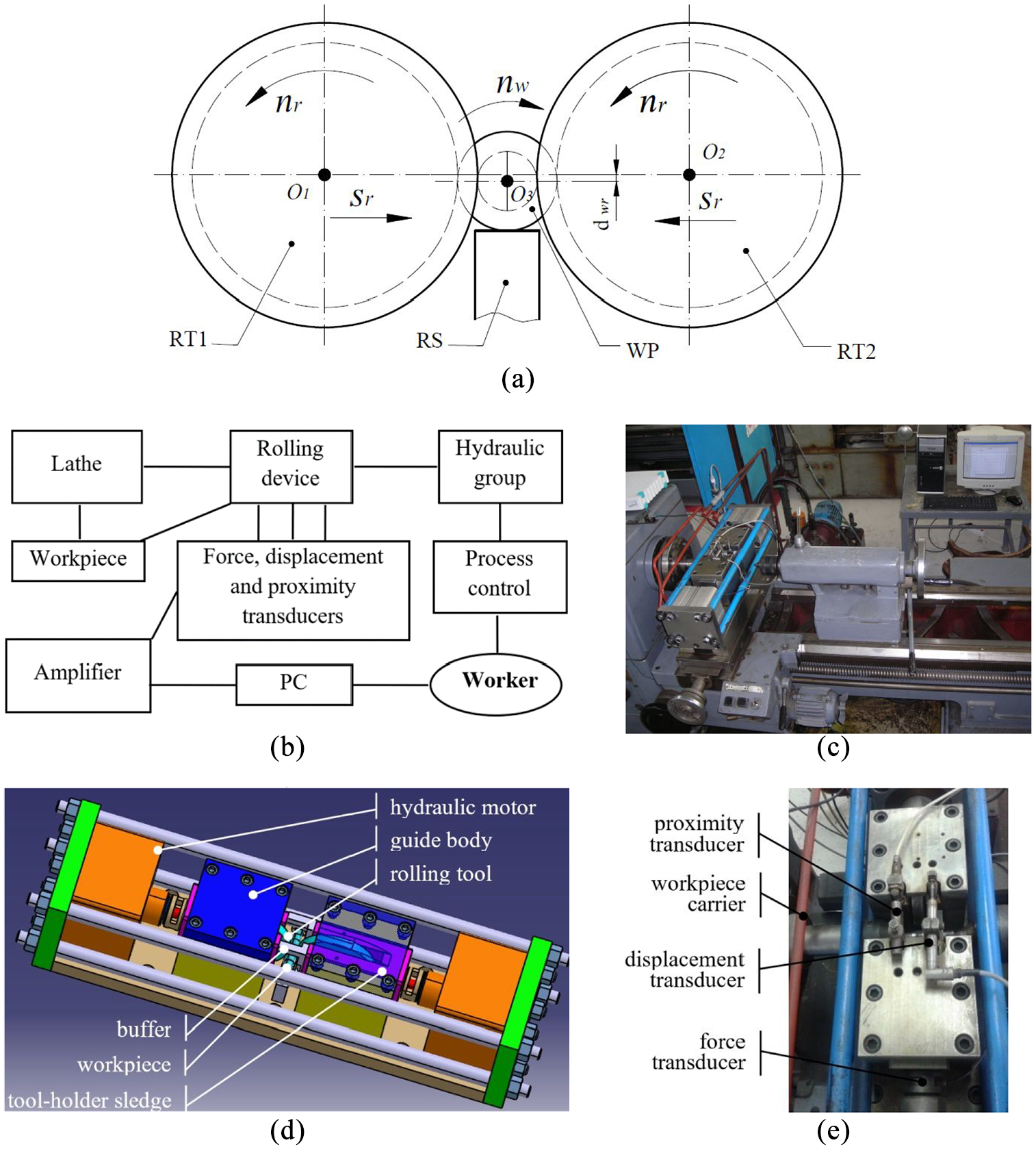
Experimental system for the radial cold-rolling: (a) kinematic scheme, (b) general scheme, (c) general photography,(d) CAD model of the rolling device, and (e) positioning of transducers.
This device is fixed on a lathe carriage and the working cycle (performed by the two roller-tools) is semi-automated: penetration, calibration, withdrawal. The roller-tools (RT) are entrained in rotation by the workpiece at the speed (nr) (rpm) as a result of the contact between the rolls and the workpiece. The radial feed of the roller-tools (sr), the same for the two rolls, but in the opposite direction, is generated by two hydraulic motors Figure 2(d). The maximum force developed by each hydraulic engine, denoted as maximum set force (Fm), can be adjusted by setting an equivalent pressure (ph) in the two hydraulic engines.
The rolling speed (v) can be adjusted by the lathe speed setup (nw), while the radial feed of the roller-tools (sr) cannot be directly adjusted, except through the pressure p in the hydraulic motors. The penetration depth of the roller-tools (h) can be limited using buffers. When this depth is reached (hmax), the calibration of the profile can be performed by maintaining in rotation the roller-tools in the final position to give the piece a high geometrical and surface quality.
The experimental system allows monitoring the roller-tools displacement, the radial force, and the calibration time. Measurement of the roller-tools displacement is carried out with a displacement transducer WAL20, Figure 2(e), and with a resolution of 1 μm. The radial force (force evolution in the displacement direction of the roller-tools) (Fr) is measured using a force transducer KMR 200 WAL20, Figure 2(e), whose measurement error is equal to 1%. The calibration phase is controlled by a proximity transducer PY 152, allowing the adjustment of the roller-tools to be held in time in this position.
Penetration curve of the roller-tools
In the finite element model, it is necessary for the numerical simulation of the rolling process, to define the penetration curve of the roller-tools in the material. Our rolling process is performed with variable radial feed (sr) because the time required to reach the set maximum pressure in the experimental system is comparable to the time required to obtain the profile. The experimental shapes of the penetration curves of the roller-tools into the material, Figure 3, are similar to the two processed profiles, three areas are being highlighted:
- first area (I) with progressive acceleration, at the beginning of the process, is associated with the elastic deformation of the system;
- second area (II) with an almost constant evolution speed and associated with the plastic deformations of the workpiece;
- third area (III) with a deceleration to a possible saturation and which appears when the profile of the piece has been made or the tool-holder sledge reached the buffer.
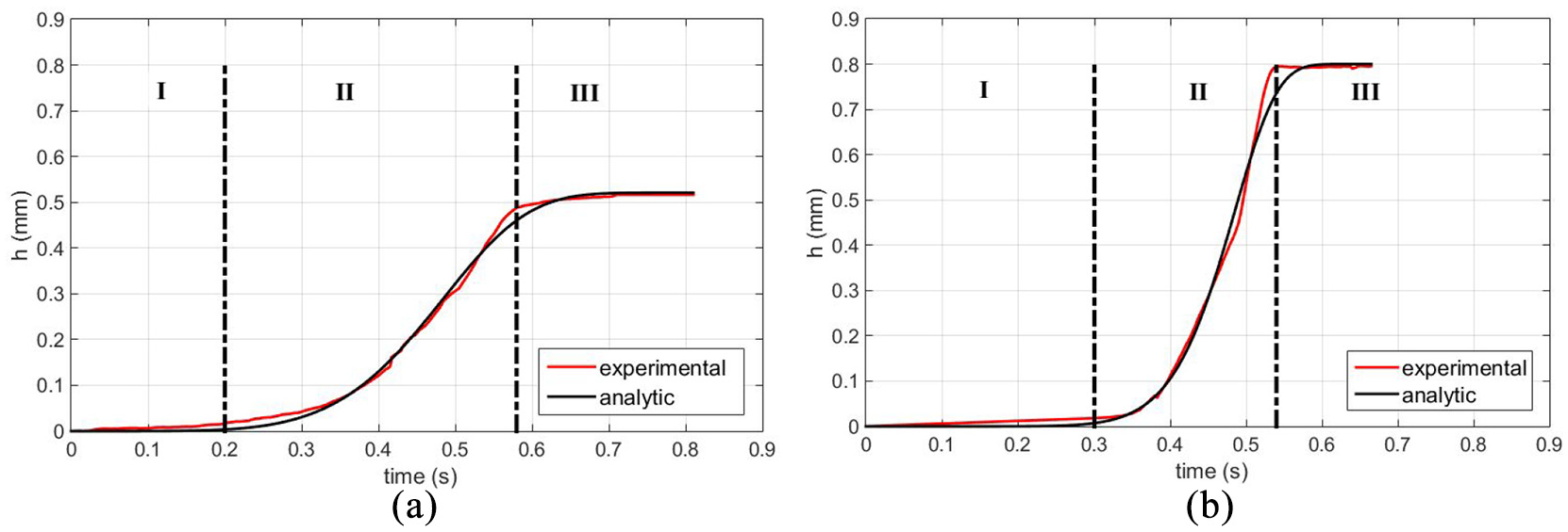
The penetration curves of the roller-tools for rolling conditions n = 1600 rpm, p = 36 bar: (a) metric profile and (b) trapezoidal profile.
The penetration depth of the roller-tools in the material (h) depends on several factors and the most important are the rolling speed (v), the maximum set force (Fm), and the maximum penetration depth of the roller-tools (hmax). The form of the law that best describes the evolution of the roller-tools penetration in the workpiece was established after several attempts as follows 29 :

where: t is the process time and the coefficients
To express the dependency of the coefficients α and β on other rolling conditions (v, Fm), we performed a multivariable analysis using a design of experiments technique,30,31 aiming to determine the parameters of functions as:


For each type of profile, 12 experiments were performed consisting of the variation of the rolling speed (v) and the set maximum force (Fm). First, the α and β coefficients for each experimental case were determined by regression analysis. Thus, based on the values of the coefficients α and β previously determined, the six coefficients
The functions of the coefficients α and A of penetration curves of the roller-tools.
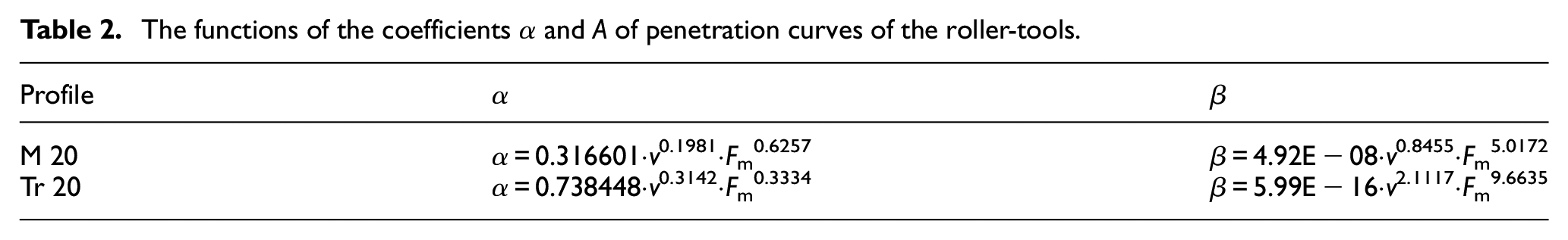
Thus, the curve of penetration of the roller-tools used in the numerical model can be obtained through equation (1), in which the coefficients α and β are obtained by setting the values of the process parameters v and Fm in the functions (2) and (3).
Numerical procedure
Numerical model
The numerical simulations were performed with Abaqus/Explicit software. The numerical model used in this study was presented in detail by Nitu et al. 32 A synthetic overview is presented hereafter.
The workpiece used in the simulation has the same (cylindrical) shape and dimensions (diameter and length) as the one used in the experiments. The best compromise between computing resources and results accuracy consists of a different meshing in the axial and radial direction, depending on the profile deformation degree. In the deformed areas C3D8R (8-nodes solid hexahedral elements with reduced integration) are used while in the middle of the workpiece (undeformed area) C3D4R (4-nodes solid tetrahedral elements with reduced integration) are used for the meshing. The different dimensions of the elements in these areas were established based on the profile step p.
The roller-tools have a profile associated with the profile to be obtained and are modeled by analytical rigid surfaces (Figure 4). The workpiece is free and in contact with the piece-support, and the roller-tools has two degrees of freedom: a rotation around its axis (given by the rolling speed v), and an in-feed translation defined by the curve of penetration h(t), equation (1).
Overview of ABAQUS model for numerical simulation: (a) the roller-tools and (b) kinematic of the process.
The type of contact between the surfaces is a “surface-to-surface” one, the friction coefficient between the rolls and the workpiece was set at 0.3, and 0.01 between the workpiece and the base. These values were chosen based on the literature review33,34 and preliminary simulations.
The behavior of the material is defined as follows:
- the elastic behavior of the workpiece is modeled by assuming isotropic elasticity, with the values of Young’s modulus, E = 210 GPa and Poisson’s ratio, ν = 0.3.
- the plastic behavior is described using the von Mises criterion with the assumption of isotropic hardening. Accordingly, the yield function is given by:
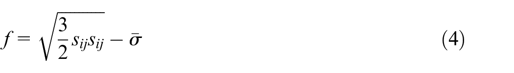
where
The current yield stress

where K, n, S, A, and B are material parameters, and ε is the effective strain.
The identification of the five parameters, equation (5), was performed by fitting the compression test data with a gradient method implemented in a FORTRAN program. 32 It was obtained: K = 542.5 MPa, n = 0.135, S = 217.6 MPa, A = 0.99, and B = 9.91.
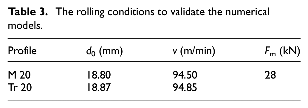
The numerical model validation was performed by comparing the simulation results with the experimental ones, under the rolling conditions presented in Table 3, where d0 is the diameter of the workpiece.
The rolling conditions to validate the numerical models.
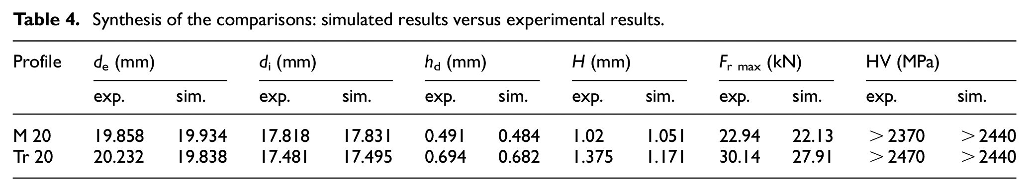
The compared output parameters were: profile dimensions (de and di), depth of deformation (hd), profile height (H), maximum radial force (Fr max), and the HV0,3 microhardness level, which is measured in the axial section in the zone of maximum hardening (the transition region of the flanks with the base of the profile).


A Toolmaster 310-P profile projector, with an accuracy of ±0.5 µm, was used to measure the geometric parameters of the profile (d0, de, and di).
Micro-hardness measurements were made by the Vickers method (300 g load) in the axial section of the tooth, using a Zwick Roell ZHV equipment. These values were expressed in (MPa) by multiplying them with the gravitational acceleration value (9.81 m/s
2
)). The HV0,3 (micro-hardness measurements) and
A summary of the comparisons between simulated results versus experimental ones is shown in Table 4 and Figure 5. Thus, based on these comparisons it is concluded that all calculated outputs were in very good agreement with their experimental values.
Synthesis of the comparisons: simulated results versus experimental results.
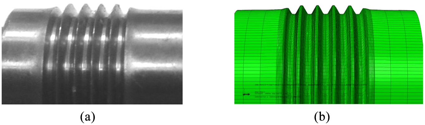
The part obtained by radial cold-rolling: (a) experimental shape and (b) FE simulated shape.
Simulations plan
The developed numerical model in the ABAQUS environment was used to analyze the influence of the maximum set force (Fm) and the diameter of the workpiece (d0) on the productiveness and the quality of circular profiles. The penetration curves of the roller-tools used in this model are defined by the equation (1), the values of the coefficients
For the maximum set force (Fm), we selected three values in geometric progression 42, 63, and 94.5 kN that are higher than those used in the experiments. For the workpiece diameter (d0), we selected two values that are symmetrically arranged around the one used in the experiments (determined by the law of volume constancy 1 ): 18.75 and 18.85 mm for the metric profile, respectively, 18.82 and 18.92 mm for the trapezoidal profile. The different numerical simulations are detailed in Table 5.
Variation of the process parameters in the numerical simulations.
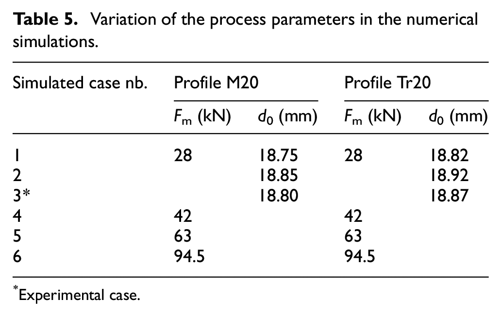
Experimental case.
Results and discussions
The simulations results that were analyzed in this study are:
- the profile forming time (td), the maximum radial force (Fr max), and the distribution of equivalent deformations
- the profile dimensions (internal diameter di and outer diameter de), the depth of deformation (hd), and the equivalent strain distribution
Influence of the maximum set force
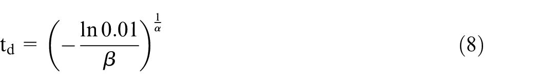
The dependence of the profile forming time (td) on the maximum set force (Fm) is obtained by inputting in the relation (8) the values of the coefficients α and A that are expressed by the relations (2) and (3):
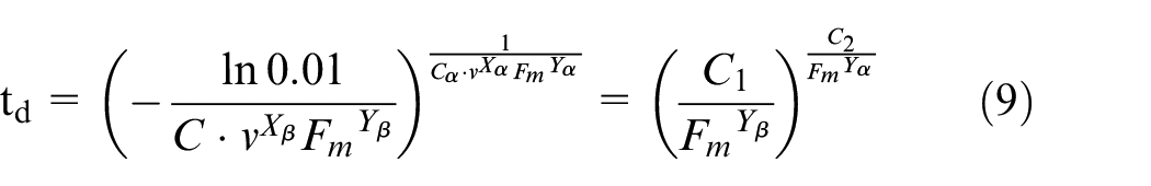
where C1 and C2 are invariable in relation to the maximum set force Fm:
Considering the values expressed in Table 2 for the six coefficients
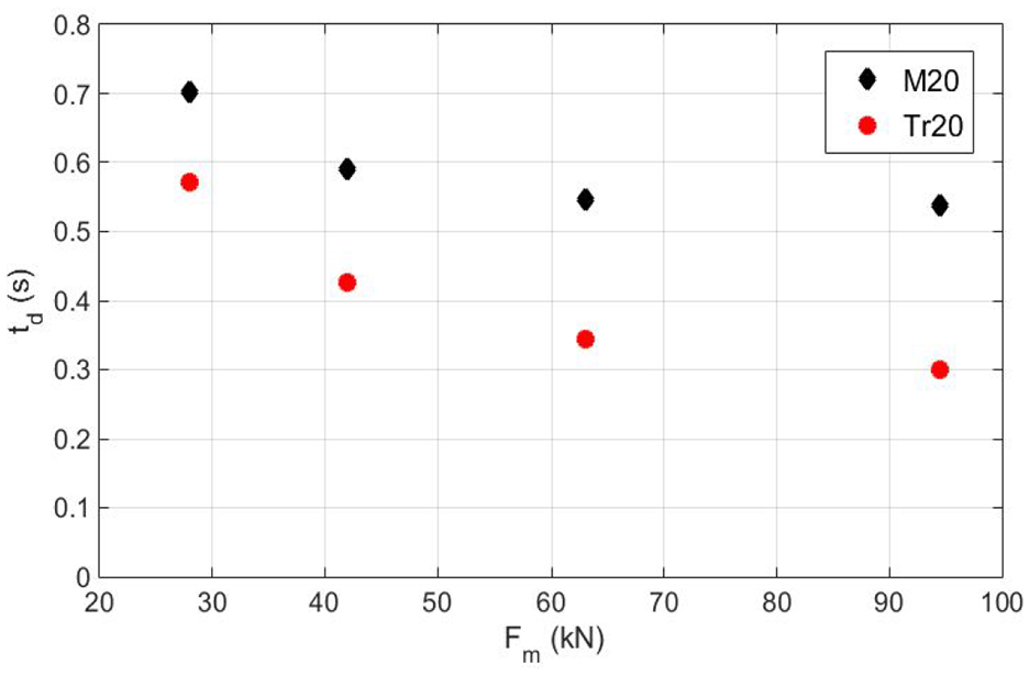
The dependence between the profile forming time, td, and the maximum set force, Fm.
The analysis of these dependencies allows drawing the following conclusions:
- For a given value of the maximum set force (Fm) the trapezoidal profile forming time is lower than the metric one. Because deformation during thread rolling closely resembles the indentation of a semi-infinite body,13,36 the favorable geometry of the trapezoidal profile (lower flank angle) explains this evolution, leading to the rapid penetration of the roller-tools in the workpiece.
- There is a slight flattening trend of the two curves, which is found at the values of the maximum set force Fm greater than 60 kN for the metric profile, respectively, 90 kN for the trapezoidal profile. This finding is related to the hyperbolic shape of the dependence between td and Fm (see equation (10)). These evolutions of the profile forming time are due to the behavior of the material, namely its hardening: in the plastic deformation domain, according to the constitutive equation of the material, 37 the increase in tension becomes smaller and smaller as the deformation increases, thus slowing down the intensity of the deformation process and, consequently, the increase of the profile forming duration.
The dependency of
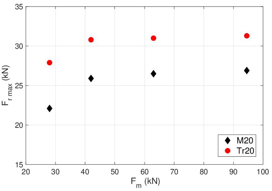
The dependency between the maximum radial force Fr max and the maximum set force, Fm.
It is found that for the same value of the maximum set force (Fm), the maximum radial force (Fr max) is higher for the trapezoidal profile than for the metric one. This is because the flat base of the trapezoidal indenter (roller-tools) leads to deeper penetration and hardening of the workpiece. 14
There is a trend of flattening for the two curves which appears when the maximum set force (Fm) exceeds 42 kN. The levels of these flattenings are 2 kN for the metric profile and 32 kN for the trapezoidal profile. This flattening is because the maximal radial force depends on the penetration depth of the tool into the workpiece (h) and this maximum penetration depth is limited to a required value (hmax) which depends on d0 and di (see equation (6)).
Figure 8 shows
- The largest strains always appear at the bottom of the profile (the maximum value being in the root of the flank) and are propagated radially toward the interior of the material. Although these strains within the tooth are lower, the tooth is hardened (
- For the metric profile, the material hardening is significantly influenced by the maximum set force (Fm). For example, the most hardened area (
- For the trapezoidal profile, the material hardening is less dependent on the maximum set force, the area strongly hardened (
- The maximum material hardening is obtained in the cold rolling process with lower maximum set forces, meaning that the penetration of the roller-tools is performed at lower feeds. The material hardening is greater in the cold rolling process for the trapezoidal profile than the metric one and this can be explained by the greater forming depth of the profile.13,14
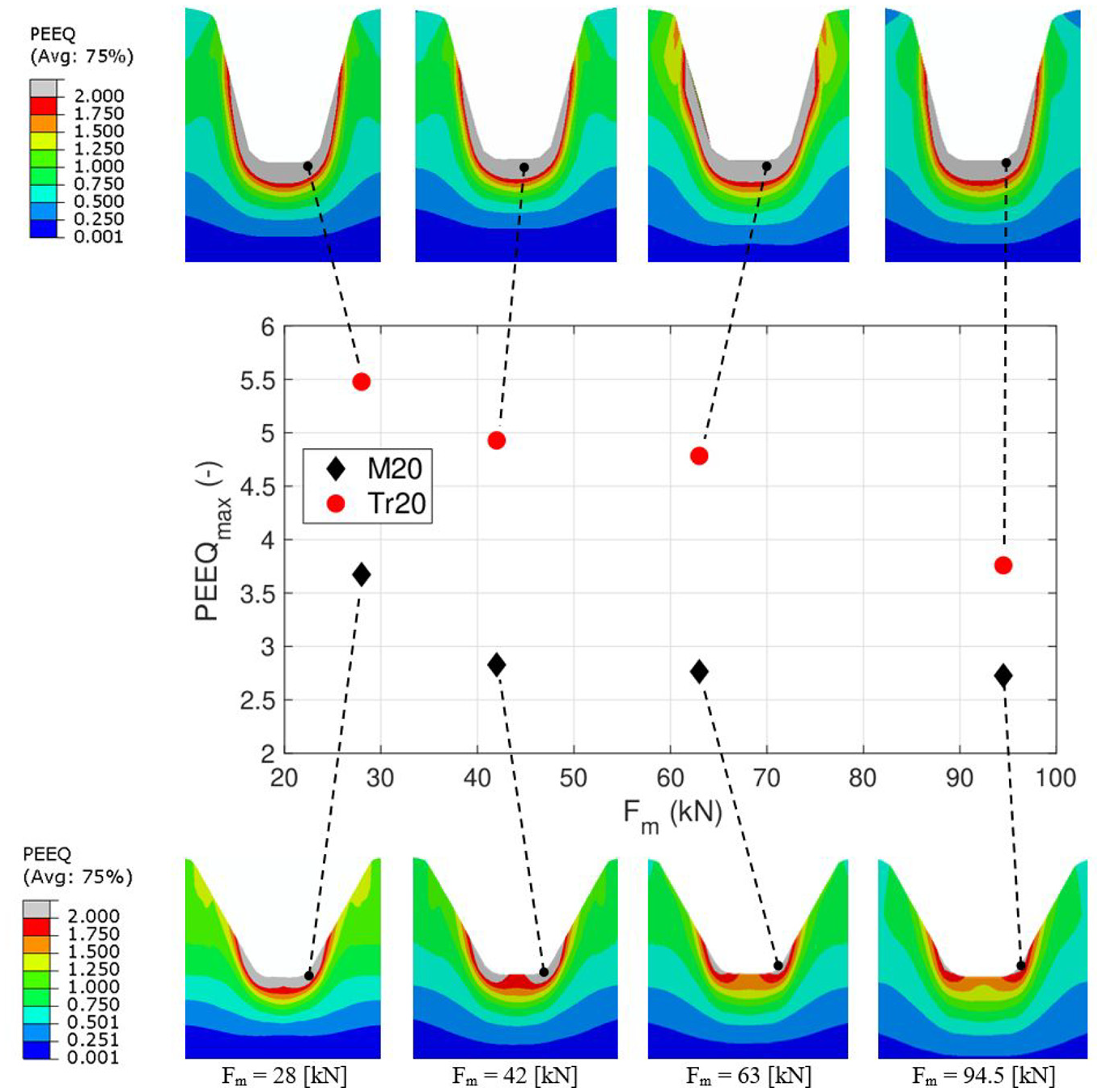
Distribution of the equivalent plastic strains (PEEQ) with respect to the maximum set force Fm.
Influence of the workpiece diameter
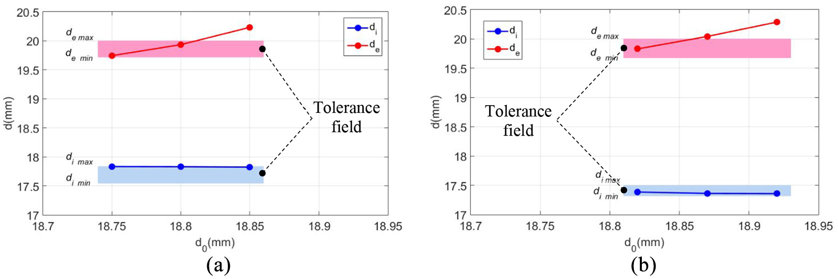
Dependence of the profiles diameters obtained by radial cold rolling with respect to the workpiece diameter: (a) metric profile and (b) trapezoidal profile.
Regarding the tolerance margin of both the inner and the outer diameters of the profiles, it can be seen that:
- For the metric profile, the resulted dimensions are adequate if using a workpiece with a smaller or equal diameter to the one determined by the law of volume constancy (d0≤18.80 mm);
- For the trapezoidal profile, the obtained dimensions are appropriate if using a workpiece with a diameter smaller than the one determined by the law of volume constancy (d0 <18.87 mm).
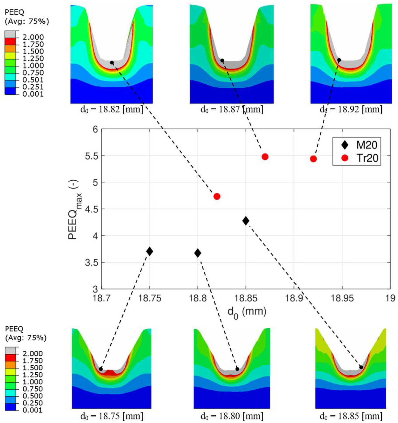
Distribution of the equivalent plastic strains (PEEQ) with respect to the workpiece diameter, d0.
Summary and conclusions
The research presented in the paper consisted of running several numerical simulations of the cold-rolling process with two roller-tools, of radial grooves with metric and trapezoidal profile, using a numerical model previously validated. The penetration curve of the roller-tools in the material was introduced in the simulation as an analytical function and was determined based on experimental researches. The dependence of the curve penetration coefficients on the rolling conditions (rolling speed, v, and maximum set force, Fm) was established by a multivariable analysis using the design of the experiment technique.
The varied parameters in the simulations were the maximum set force (Fm) and the diameter of the workpiece (d0). The analyzed results were the profile forming time (td), the maximum radial force (Fm), the distribution of the equivalent plastic strains in the axial section of the profiles (PEEQ), and the profile dimensions (de and di).
The main conclusions drawn from this work can be summarized as follows:
- rolling with higher maximum set forces leads to (i) decreasing the profile forming time (td) up to a limit level, (ii) increasing the radial maximum force (Fr max) up to a limit level, and (iii) decreasing the area strongly hardened and the maximum values of equivalent plastic strains (PEEQ) in the axial section of the rolling profiles.
- the use of workpieces with a smaller diameter than the one determined by the law of volume constancy leads to profiles with conforming dimensions (within the specified tolerance field), while the inner diameter of the profile is directly influenced by the adjusting dimension and the stiffness of the technological system.
To define the optimal process conditions, the following criteria are considered:
- Productivity, which can be appreciated with the profile forming time (td);
- Material hardening, which can be appreciated based on the distribution and the level of the equivalent plastic strains (PEEQ);
- Profile dimensions, described by the inside diameter di and the outer diameter de.
Based on the results analyzed in section 4 and on the optimality criteria defined above, we can establish the optimum process conditions:
- to obtain a good compromise between high productivity (lower profile forming time) and a higher and more uniform material hardening (PEEQ maximum), the value of the maximum set force (Fm) should not be too high. In this study, the following values are considered as suitable: Fm between 40 and 50 kN for the rolling of the metric profile, and Fm between 50 and 60 kN for the rolling of the trapezoidal profile, respectively.
- to obtain dimensions of the profile within the specified tolerance field, the diameter d0 of the workpiece must be between 18.75 and 18.80 mm for the rolling of the metric profile, and between 18.79 and 18.84 mm for the rolling of the trapezoidal profile, respectively.
Further research can be done by considering another parameter of the process, for example, the radius of the tip of the tool, or by extending the investigations to other profiles or materials used in this field.
Footnotes
Appendix
Declaration of conflicting interests
The author(s) declared no potential conflicts of interest with respect to the research, authorship, and/or publication of this article.
Funding
The author(s) received no financial support for the research, authorship, and/or publication of this article.