
Abstract
The underwater friction stir processing is used for development of aluminum metal matrix composite (AA2219-Y2O3) foam. For development of foam, holes with different diameter in the mid thickness of plate were filled with a mixture of TiH2 and aluminum powder and underwater friction stir processing was used to mix this mixture in aluminum metal matrix composite. Then precursors extracted from the processed zone and heated upto 650°C in a furnace for development of foam. The effect of diameter of hole, number of passes and the tool rotation direction has been studied on the foam cell size and static and dynamic compressive behavior of the foam. It is found that as the diameter of hole increases, the size of pores increases. The distribution of pores is better with higher number of passes and increasing the hole diameter. The quality of foam further improves by reversing the tool rotation direction. The developed foam has different pore size varies from 0.7 to 2.7 mm depends on the FSP parameters. Based on the size of pores and their distribution the relative density ranges from 0.1 to 0.78. The foam produced with 4 mm hole diameter has best static and dynamic compression properties.
Introduction
The aluminum foams are used in automobiles due to its lightweight with superior mechanical properties. It is also used in many industries due to its good energy absorption capability during fracture, good thermal and sound insulation properties. To develop aluminum foam, it is required to develop a precursor which then further heat treated for foaming process.1,2 The precursor is developed by homogeneous mixing of aluminum powder with foaming agent. This mixture then compacted and sintered by some means. 3 This sintered mixture is known as precursor which is further heat treated to release the gases by decomposition of the foaming agent. But innovations in the field of friction stir processing (FSP) opens new era of manufacturing through which the product can be developed in faster and easier way.4,5 It added benefits of FSP which leads to improve the mechanical properties of the product. 6 In recent years researchers are focused to utilize this new technique of manufacturing for development of foam. Using FSP for development of foam enhances the process capability and also at the same time reduces the manufacturing cost.7,8 In this regard Hangai et al. utilized the FSP for development of precursors to produce foam.9,10 In his approach a mixture of foaming agent (TiH2) and stabilizing agents are placed between two aluminum plates. Then this mixture was mixed in the aluminum matrix with the help of FSP. In the same way, some other researchers also utilized FSP to mix the foaming material to the substrate by stirring action of tool.11–13 Along with that, for more uniform distribution of the foaming agent into the substrate, researchers increased the number of FSP passes and reversing the direction of tool rotation.14,15 After FSP, samples are taken out from the processed zone of the plate and further heat treated to develop the foam. 16 This process is simple and economical because aluminum plates which are available commercially can be used for development of foam rather than using aluminum powder which is expensive. 17 Thus using FSP for development of foam is beneficial but at the same time it was also reported in literature that the temperature during processing of aluminum plates by FSP, reaches approximately upto 450°C–550°C.18–20 This temperature is close to the temperature on which the foaming agent (TiH2) decomposes. 21 Therefore, some amount of H2 gases escaped from the processed region during frictional stirring. Therefore, a need is arrived to develop a process where the temperature generated during processing is lower than the temperature of decomposition of foaming agent. It is also reported that only placing the foaming agent in between two plates is not sufficient for development of good quality foam. Because it limits the amount of foaming agent to be filled in between the plates and if excess material is placed in between the plates, chances of formation of tunnel defect is very common.22,23 Thus, it is required to select any other method to mix the foaming agent in the substrate. Along with that, it is also required that the developed foam should have good properties like high strength-to-weight ratio. All these problems associated with the development of good quality foam have been meagerly focused in the literature.
So, understanding these problems associated with the development of foam, a new approach has been used in this study to produce the foam. The FSP is adopted for development of precursor by mixing of foaming agent into the substrate. But as reported in the literature, the temperature generated in the processing zone during FSP is high enough to decompose TiH2. So to reduce the temperature, underwater approach of FSP has been adopted. It also helps to reduce the release of H2 gas by reducing the decomposition of TiH2 during processing. The mixing of foaming agent and stabilizing agent into the substrate is also a critical issue which is solved in this research by obtaining a novel approach of making holes on thickness side of the plate along the length. It enhances the proper mixing of the TiH2 and stabilizing agent into the substrate and also helps in trapping of H2 gases in the processed region. In addition of this it is also required that the developed foam should have good strength which cannot possible by using pure aluminum or aluminum alloy. The foam developed by pure aluminum or aluminum alloys have poor compressive strength due to easily deformation of cell walls during compression. The composite material has better mechanical properties as compare to aluminum alloys. Thus in this research, aluminum metal matrix composite is selected which is made of aluminum alloy AA2219 and reinforced with yttrium oxide (Y2O3) to develop high strength foam. Then the developed foam has been characterized based on the effect of hole diameter, number of passes and the direction of tool rotation.
Experimentation
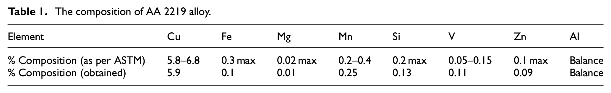
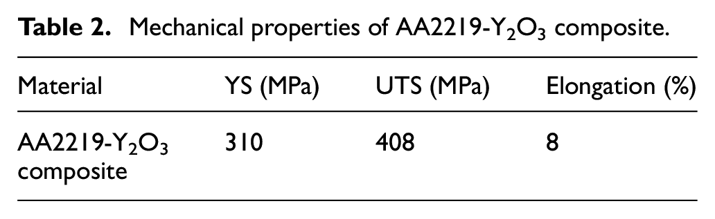
The AA2219 is widely used in aerospace and defense applications due to its high strength-to-weight ratio and toughness. The chemical composition of the AA2219 is obtained from optical emission spectroscopy and presented in Table 1 and compared with the ASTM standard which is found in the range. This alloy is used to develop composite by adding Y2O3 into it by FSP. The AA2219-Y2O3 composite is developed by mixing the Y2O3 in AA2219 aluminum alloy plate by FSP. The Y2O3 is filled into the substrate by making hole on the thickness side of the plate and FSP is used to mix it into the substrate. For making the composite the weight percentage of Y2O3 was taken 10% because it provided best mechanical properties and thus used here for making the foam. 23 The Y2O3 has excellent strength, high hardness, high melting point, and thermal conductivity and low coefficient of thermal expansion. 24 By adding the Y2O3 into the aluminum substrate, the strength, corrosion resistance and wear properties are improved and thus it is used for making composite.23,24 The developed AA2219-Y2O3 composite has good mechanical properties as obtain from tensile testing and presented in Table 2. This composite (AA2219-Y2O3) plate is used for development of aluminum foam by friction stir processing in present study. The dimension of the plates which was used for making foam is 100 mm × 100 mm × 8 mm. The thickness of the plate is selected in such a way that there is a sufficient material available for proper mixing of foaming agent into the substrate. Also, after development of foam proper samples can be extracted for characterization.
The composition of AA 2219 alloy.
Mechanical properties of AA2219-Y2O3 composite.
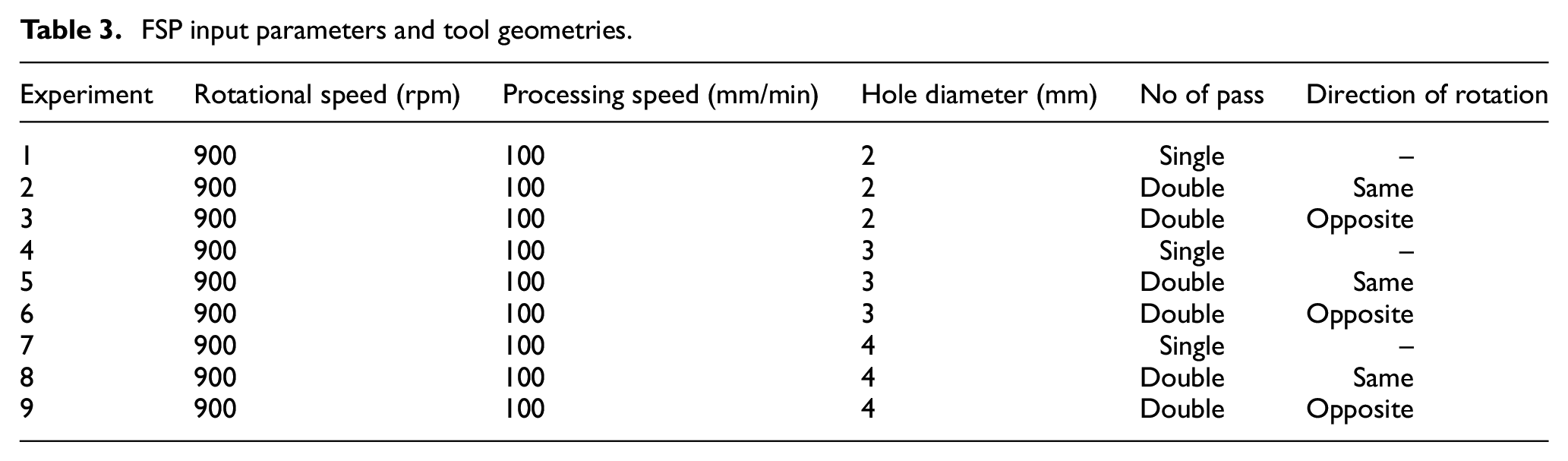
A special designed non consumable tool of H-13 hot-die steel with 20 mm shoulder diameter and cylindrical threaded pin of 8 mm diameter is used. The Al composite plates are drilled with different diameters along its mid thickness. The fabrication of precursor is done by inserting a mixture of TiH2 and pure aluminum powder in a ratio of 40% and 60% respectively by weight in these pre-drilled holes. Single hole has been created for each experiment and three samples have been extracted for examinations. The TiH2 is used here for development of foam because the decomposition temperature of TiH2 is just below the melting point of aluminum. Thus the decomposed gases not escape from aluminum matrix and entrapped into it while aluminum is in semi liquid or plastic state and provides better foaming properties. Using TiH2 is also good because it has a stable temperature to decompose than the other foaming agent like calcium carbonate, magnesium carbonate and dolomite. 25 Also, the composition of TiH2 and aluminum powder used in these experiments provides better foaming capability obtained from the trial experiments. After filling the mixture of foaming agent and Al powder, the plate is clamped on a fixture and whole setup is submerged in water. The water level is maintained 30 mm above the top surface of the plate and the temperature of water is maintained by continuous supply of excess water from external source. The whole arrangement is attached on the bed of milling machine and the FSP is done in the underwater condition in which the tool traverse is aligned with the axis of hole. The schematic diagram of the whole set up is shown in Figure 1(a). The Figure 1(b) shows the actual processing of composite plates in underwater condition. The reason for performing the FSP in underwater condition with excess flow of water so that the temperature of water does not raise high enough in the processing region. 26 The underwater FSP helps the mixing of TiH2 and Al particle in the base plate properly. Along with that it also helps in reducing decomposition of TiH2 during processing and thus decreasing the chances of escaping of H2 gases from the stir zone. All experiments have been done with a fixed tool tilt angle of 2° from vertical axis. 27 The FSP of composite plate has been done with different hole diameter along with different number of passes and different tool rotation direction as presented in Table 2. The ranges of parameters are selected after many hit and trail experiment so that their effect on the properties can be observed properly. The upper and lower limit of the diameter of hole decided based on the visual inspection of precursor. The precursor which was found to be free from tunneling defect was further used for development of foam. Because, if the precursor has tunneling defect then the gases formed during decomposition of TiH2 passes out from this defect and reduces the quality of foam. Similarly, the rotational speed also has significant influences on the stirring action of the processed zone. It enhances the properties up to certain limit and after that causes formation of defect due to turbulence in the processed zone. Thus in this research optimum value of rotational speed has been used for making the foam. Along with that, the stirring action also increases the amount of heat in to processed zone. With excess heat, the viscosity of aluminum decreases, consequently the gas bubbles merge with each other. Accumulation of bubbles forms big pores and distribute them non-uniformly in the processed zone. It is also found that as the diameter of the hole increases beyond 4 mm causes, formation of tunneling defects during FSP which decreases the quality of foam. Also, the diameter less than 2 mm has insufficient foaming agent for development of foam. Similarly, the optimum values of welding speed of the tool were selected in such a way that it reduces the formation of defects. The rotational speed also has significant influence on the stirring action in processed zone. It enhances the properties up to certain limit and after that causes formation of defect due to high turbulence in the processed zone. Thus in this research optimum value of rotational speed has been used for making the foam. Table 3 represents the selected set of process parameters to produce defect free precursor. After FSP, samples were extracted from the processed zone as shown in Figure 2. These samples are further heated to develop the foam. The samples are then extracted for testing by precision cutter and by rough policing on emery paper. The various mechanical properties of the foam were determined by different examination like macrostructure, microstructure, hardness, static compression and dynamic compression tests.
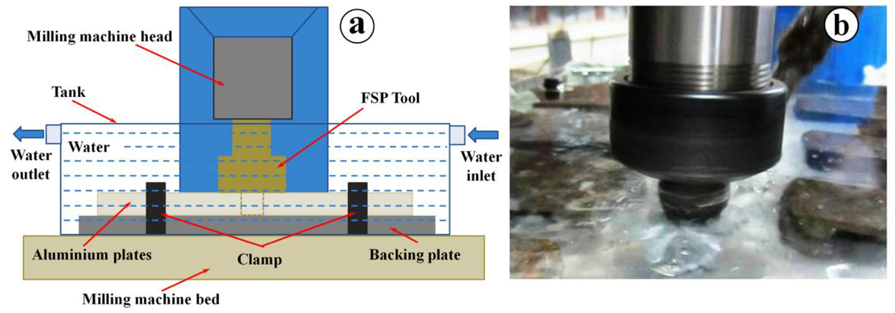
(a) Setup of underwater FSP and (b) underwater FSP.
FSP input parameters and tool geometries.
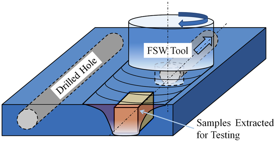
Schematic diagram of development of precursor by FSP route.
Results and discussion
Macrostructure analysis
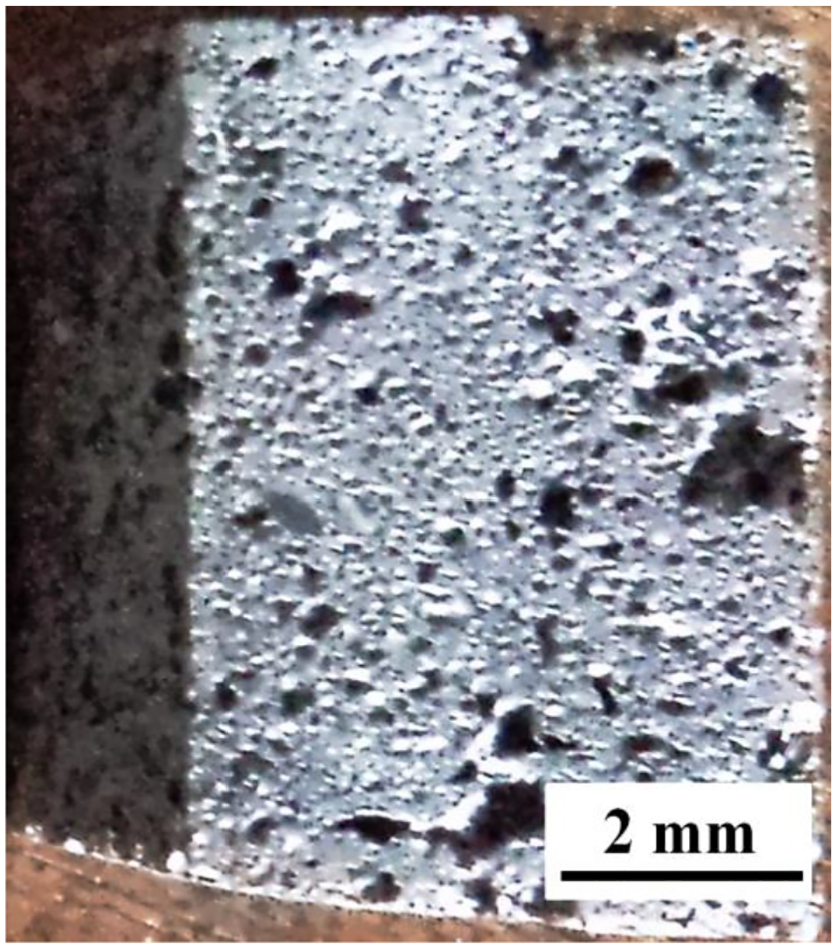
The macrostructure of typical friction stir processed section is shown in Figure 3. To evident the macrostructure of processed zone, samples were etched with modified Keller’s reagent. Some black spots are clearly evident in Figure 3 and distributed throughout in the processed zone. These black spots are clusters of TiH2 particles. It is also found that the formation of H2 gas in the processed zone is due to decomposition of TiH2 particles during tool stirring. The friction stir processing was done in underwater condition to reduce the amount of heat generation. This reduced heat lowers the temperature of processed zone but in certain spots the heat is sufficient enough for decomposition of TiH2 particles which then entrapped into the processed zone. Figure 3(a) shows the processed zone with 2 mm hole with double pass in opposite direction while Figure 3(d) shows the proceed zone in case of 4 mm hole in same conditions. The Figure 3(b) and (c) shows the distribution of TiH2 particles in case of 3 mm and 4 mm holes diameter in one direction of tool rotation with double pass condition, respectively. From Figure 3(a) to (d) it is clear that the distribution of TiH2 particles are higher when hole diameter increases. This is because the volume of TiH2 particles increase with increasing the hole diameter.
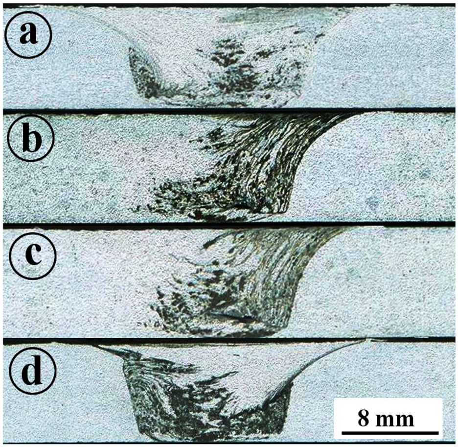
Distribution of TiH2 in processed zone in: (a) 2 mm hole, (b) 3 mm hole, (c) 4 mm hole diameter in same direction, and (d) 4 mm hole diameter in opposite direction.
Microstructure
The microstructure of interface of processed zone after FSP is shown in Figure 4. The microstructure clearly shows the distinguish line between stir zone and thermo-mechanical affected zone (TMAZ) in Figure 4(a) and (b). This distinguish line is clearly observed in all the microstructures. But in case of two pass stirring in same direction, this line is more clear (Figure 4(c)). While in case of opposite directional stirring, this line is little bit dull as shown in Figure 4(d). The processed zone has very fine grain structure as compare to the other region (Figure 5(a)–(d)). This is because stirring action of tool causes dynamic recrystallization in processed zone which creates very fine grain structure. The Figure 5(a) shows the grain structure with single pass and having a hole of 2 mm diameter. Similarly Figure 5(b) shows the grain structure of processed zone with a hole diameter of 3 mm. From these figures it is clear that the grain structure in processed zone has smaller grain. The microstructures also reviles that the grain fineness increases with increasing the number of passes (Figure 5(c)). It is found that the grain size is smallest in case of double pass with opposite directional stirring (Figure 5(d)). The thermo-mechanical affected zone has bended grains and the grain size is also depends on number of stirring passes and direction of stirring. The heat affected zone (HAZ) is ahead of TMAZ and the grain structure in HAZ is similar to the base metal which may be due to the effect of high cooling rate in underwater processing. 28 But after processing the samples are heated at 650°C and in that condition the aluminum reaches into plastic or semi-liquid state and thus the effect of microstructural changes by FSP was eliminated which is clearly visible in the Figure 6(a) to (d) in different processing conditions.
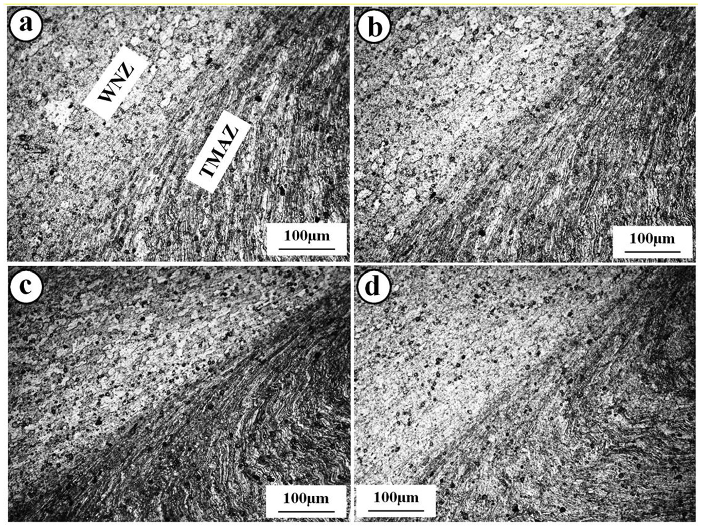
Friction stir processed region showing interface of processed zone and TMAZ in: (a) 2 mm hole diameter, (b) 3 mm hole diameter, (c) 4 mm hole diameter with double pass in same direction, and (d) 4 mm hole diameter with double pass in opposite direction.
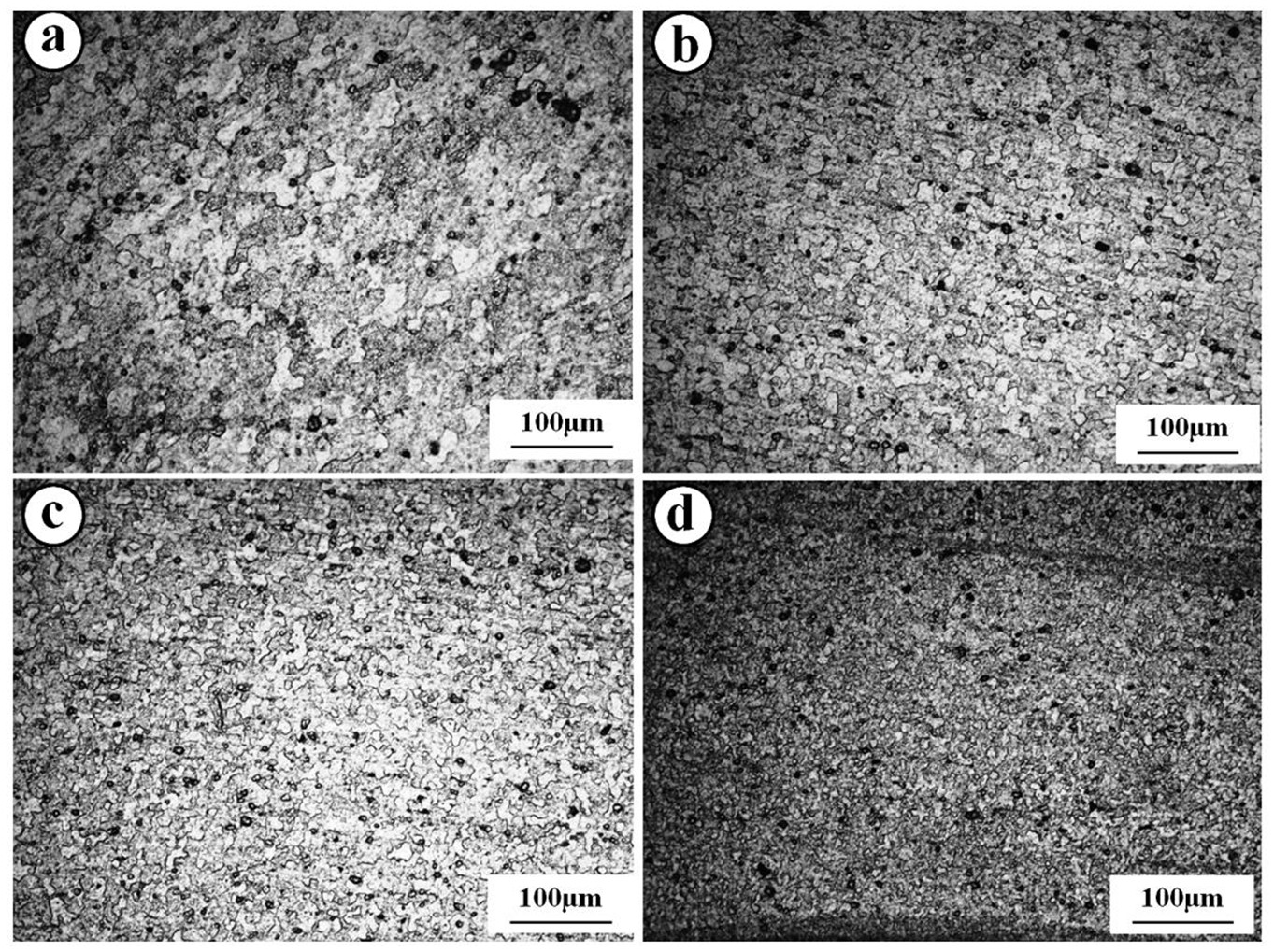
Friction stir processed region showing microstructure in WNZ in: (a) 2 mm hole diameter, (b) 3 mm hole diameter, (c) 4 mm hole diameter with double pass in same direction, and (d) 4 mm hole diameter with double pass in opposite direction.
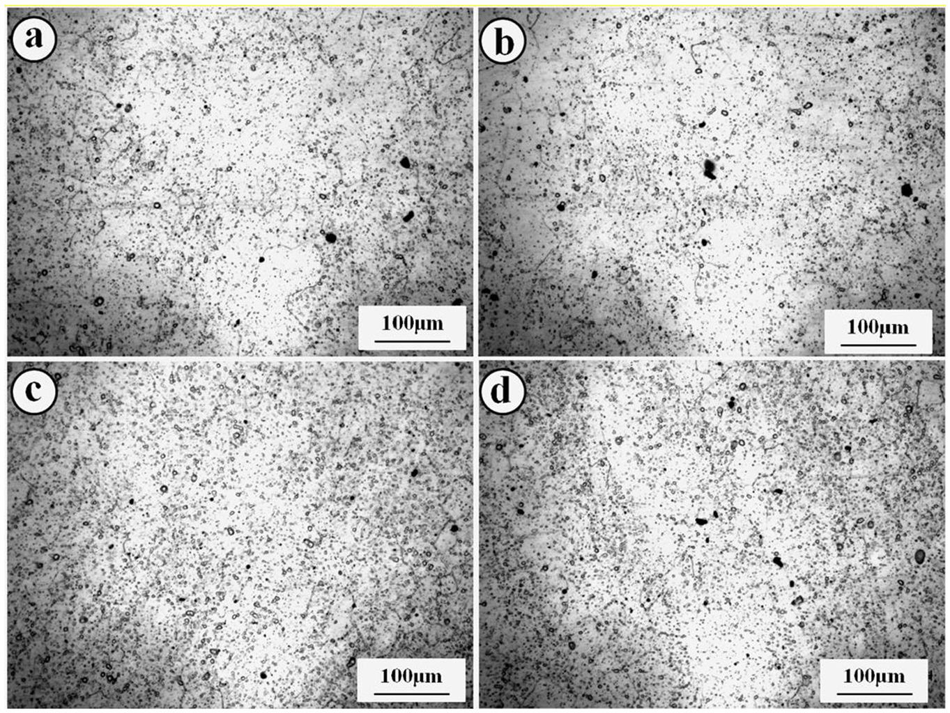
Friction stir processed region after heat treatment: (a) 2 mm hole diameter, (b) 3 mm hole diameter, (c) 4 mm hole diameter with double pass in same direction, and (d) 4 mm hole diameter with double pass in opposite direction.
The processed zone of precursor was also examined by scanning electron microscope (SEM). The SEM image shows the uneven distribution of TiH2 particle along with formation of small cavities as shown in Figure 7. The TiH2 particles are present in form of clusters at certain location of processed zone as shown in circled region in Figure 7. Along with that some porous type structure were formed (shown by arrow in Figure 7) which is due to decomposition of TiH2 during processing. 16 The decomposition of TiH2 takes place during FSP although it was done in underwater condition. This is because of amount of heat generated in processed zone is sufficient enough for certain locations where decomposition of TiH2 particles takes place. The precursor then used to analyze the energy dispersive spectroscopy (EDS) analysis. Figure 8 shows the EDS analysis of precursor of developed foam. From the EDS result it is clear that the elements like Ti and Y is also present in precursor along with the elements of AA2219 alloy.
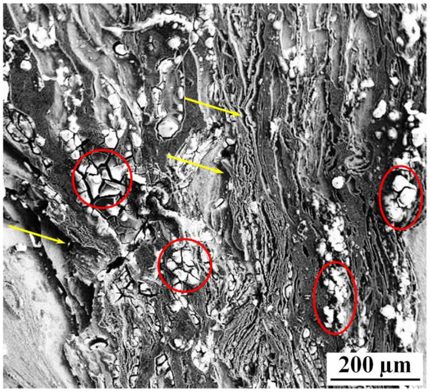
SEM image of precursor.
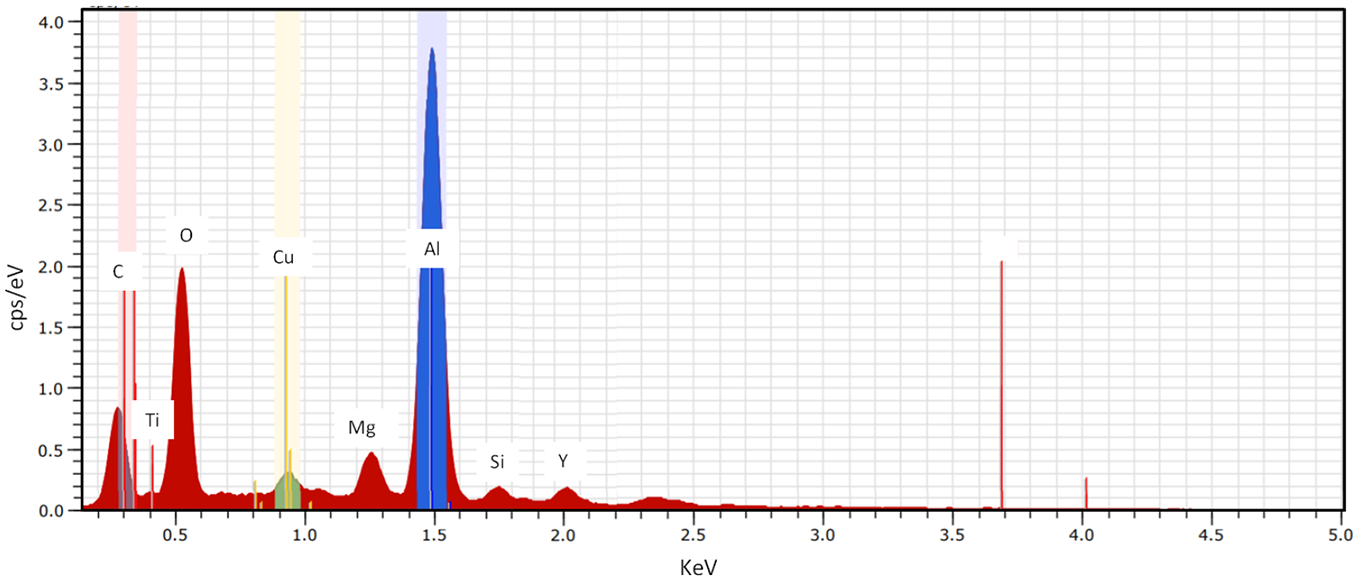
EDS of the precursor.
Hardness
The microhardness in the processed zone has been observed across the processed zone in all the conditions. It is found that the hardness in processed zone is higher at certain locations due the presence of Y2O3 composite particles. But at some locations it is found lower due to presence of pores which reduces hardness suddenly. As the number of passes increases the distribution of Y2O3 improves but same time enhances the numbers of small pores due to heat generation during stirring. Thus at certain locations hardness is higher but at some locations it is too low. As the number of passes increases the pores are increases but reversing the direction of stirring also enhances the uniform distributions of pores. Thus in the processed zone, hardness is a mixture of peaks and valleys. The hardness in different processed condition is shown in Figure 9. The hardness in processed zone shows zigzag distribution because of presence of clusters of Y2O3 and pores. The pores are causes less hardness because of improper indentation which is shown by red circles in Figure 9. The hardness which is higher at certain places is more than the near around zone is because of presence of Y2O3 particles which is shown by doted circles in Figure 9. The pores are low in numbers in case of 2 mm hole and thus uniform distribution of hardness has been found. While in case of 4 mm diameter the pores are higher and thus distribution of hardness is non-uniform. Similarly as the passes increases the pores increases and also if direction of passes reversed it enhances distribution of pores which further enhances the zigzag distribution of hardness as obtained for 3 mm hole with double pass in same and opposite direction as shown in Figure 9.
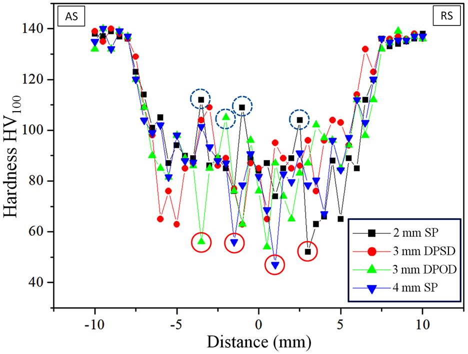
Hardness distribution in processed zone of precursor.
Development of foam
After processing, samples are extracted from processed region and heat treated at a temperature 650°C that is, above the decomposition temperature of TiH2 to develop foam.29,30 Samples are kept in furnace when temperature is maintained at this specified temperature for 5–10 min so that it becomes homogenously heated and aluminum reaches into plastic or semi-liquid state. The heating at this temperature causes formation of H2 gas by decomposition of TiH2 particles. The H2 gas then entrapped in aluminum matrix and formed bubbles. After that samples are removed from the furnace and quenched into water at room temperature so that the formed gases cannot escape from the aluminum matrix. The gases which formed bubbles in aluminum metal matrix composite are distributed in processed zone. This bubbled structure called as foam which is then sectioned for further characterization.
The foam samples produced during this experiment was first examined by visual inspection. Figure 10(a) shows the developed foam with 4 mm hole diameter with double pass in same direction while Figure 10(b) shows the foam developed at same condition but tool stirring in opposite direction. It is clear from both the figures that the foam is uniformly generated in the aluminum matrix. But from Figure 10(b) it is clear that the development of foam is more uniform when the stirring passes are in opposite direction. This is due to the fact that the tool stirring causes material flow from advancing side to retreating side.16,31 Thus in case of single directional tool stirring material accumulated in retreating side. So to avoid this situation and uniform distribution of TiH2 particles, opposite direction tool stirring is more beneficial.
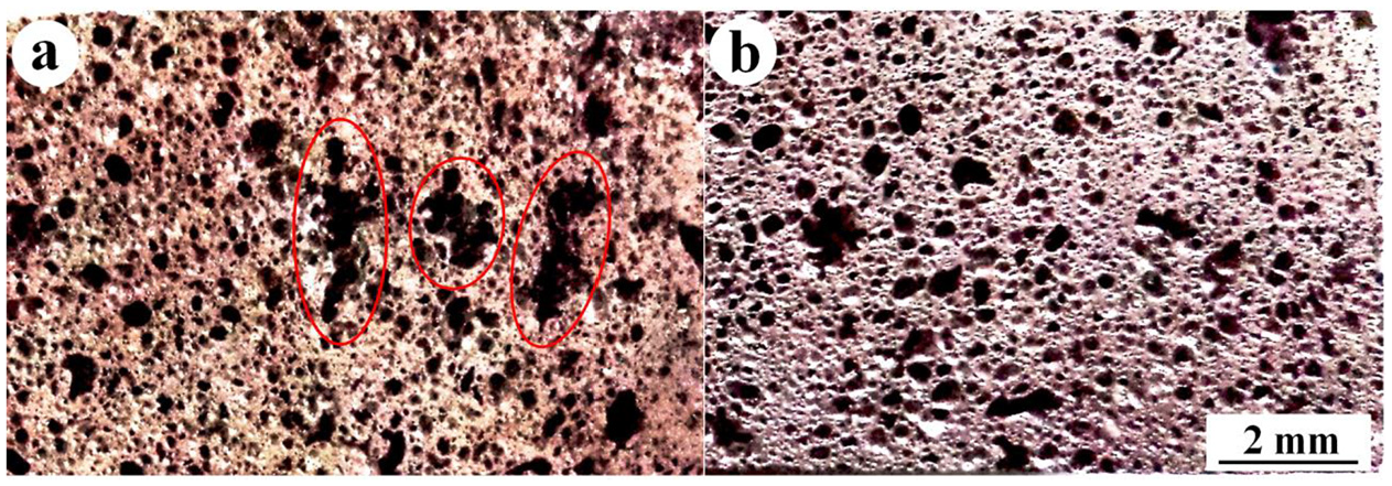
Foam structure: (a) 3 mm hole diameter with double pass in same direction and (b) 3 mm hole diameter double pass in opposite direction.
The developed foam was also analyzed by scanning electron microscopy (SEM). The SEM images are used to measure average cell size of foam. The average cell size was measured by using line intersection technique as shown in Figure 11(a). The pores in Figure 11(a) distributed uniformly but in some cases the developed foam has very bulk pores and they also not distributed uniformly (Figure 11(b)). The average cell sizes of different foam were compared with process parameters. The cell size obtained with different set of FSP parameters is shown in Figure 12 with a standard deviation of ±0.4 mm. From this figure it is clear that the foam cell size decreases with increasing the diameter of hole in single pass. But the cell size decreases with increasing number of passes. Also, the foam has smaller cell size if the direction of rotation is in opposite in different passes. The average cell size was also compared with relative density of the foam as shown in Figure 13 (with a standard deviation of ±0.16 in the measurement). It is found that as the cell size increases the relative density decreases.
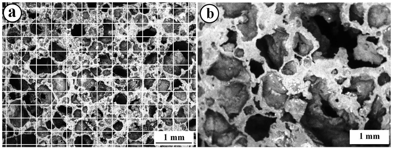
SEM image of: (a) intersection line for calculation of pore size and (b) uneven pores distribution in foam.
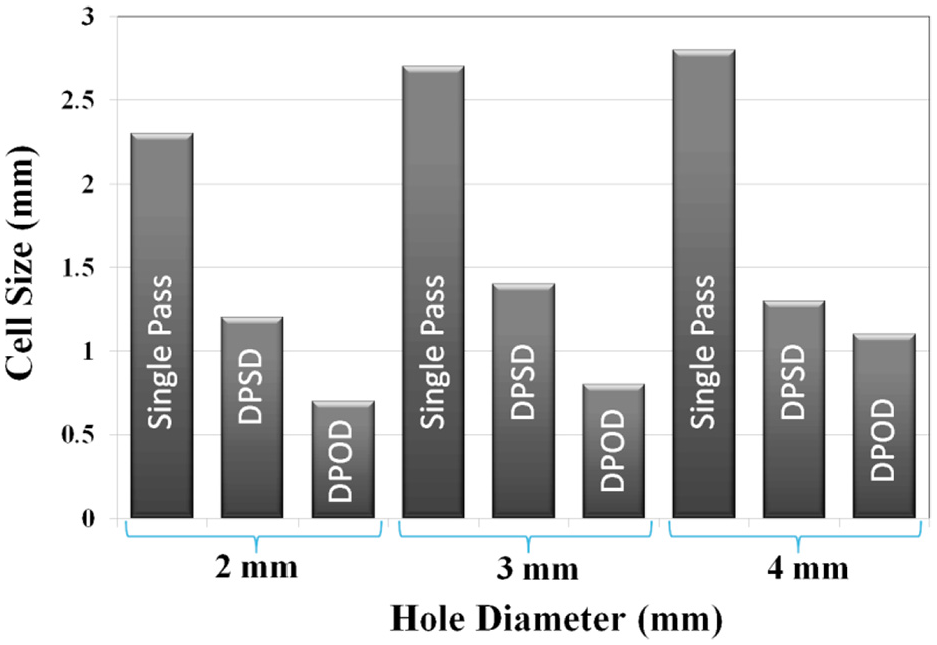
Variation of cell size with respect to process parameters.
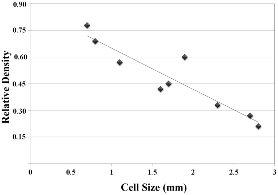
Variation of relative density with cell size.
It was found that the cell size increases with increase in hole diameter. This is obvious because increasing hole diameter increases the volume of TiH2 and thus amount of H2 gas increases which enhance the size of pores. 32 But it is observed that these pores are big in size but less in numbers per unit volume in case of single pass operation. Also, it is observed that increasing the number of passes reduces the pore size. This is due to the fact that increasing the number of passes increases the proper distribution of TiH2 particles. Furthermore, if the passes are in opposite side then pores are finer and uniformly distributed in all processing parameters.
Quasi-static compression test
Quasi-static compression test was carried out at Instron 3369 machine. The quasi-static compression test is a low strain rate compression test. In this compression test, the volume of a system changes at very slow rate which is sufficient enough to allow the pressure to remain uniform and constant throughout the system. It is used for testing compressive strength of the material in static loading conditions. In this experiment, this test was performed at strain rate of 10−3 s−1. Precision cutter was used for preparing samples having a square base of side 8 mm and a height of 5 mm as shown in Figure 14. To make all specimens in similar size for testing, rough polishing by using lower grade emery paper has been done.
The sample of foam after cutting by the precision cutter.
The results of stress-strain curve for quasi-static compression test are presented in Figure 15. The plateau stress in the present work has been taken as the average stress obtained in quasi static compression test in the strain range from 10% to 40%. It was observed from Figure 15 that during compression testing of foam, three distinguish zones is observed in which first zone is characterized as almost linear elastic region, the next zone has constant plateau region and the last zone is densification region.3,33 It is also clear from the Figure 15 that in initial region of the graph, compressive stress increased with increasing strain almost linearly due to overall elastic deformation of the cell walls. After that an increase in strain occurred without an increase in stress due to the stress concentration around the defects present in cell wall which weakened the strength of the wall. As the load increases, the foam cells begin to collapse by buckling, brittle crushing and brittle shearing. 34 After breaking of the first cell, the other cells in its vicinity begin to yield due to the stress redistribution. The stress level is almost constant in this stage due to fracture, shear and yielding of cell faces continued during this stage. It causes initiation of the new deformation mechanism of the cells and ends after some densification of the foam sample. In densification, two opposite cell faces are coming in contact and further compaction which increases the stress continuously and steeply with a limiting strain known as densification. Finally, cell faces lose their integrity and the fractured fragments tended to be compacted, causing a notable increase in stress because of increase in densification. Very limited strain occurred during this region due to densification of cellular structure. This is because of start of the cell wall interactions, which enhance the compressive resistance of cellular material. The obtained graphs by quasi-compression test of the developed foams in this research are consistent with the published literature. 30
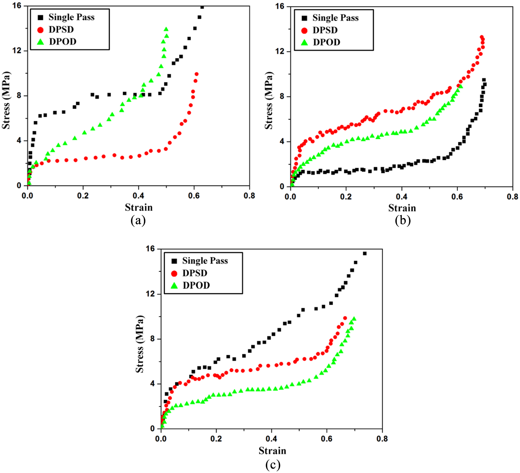
Stress-strain curve for compression test for foam obtained from: (a) 2 mm, (b) 3 mm, and (c) 4 mm hole diameter specimen.
Quasi-static tests were performed for all foam samples to obtain the compressive strength of the foams. Most of the foam samples show the universal deformation behavior in which first region shows small compression behavior with an increase in stress. This characteristic changes into a regime of very high plastic deformation after a few percentages of initial deformations of foam. This is characterized by a small slope of the stress-strain curve and known as second region. After this phase, the foam is densified and the stress level grows very quickly. The stress-strain curve for different form samples varies with their relative density and density gradients but most of the time they show same principal behavior of deformation. 35
It was observed that the density of the foam structure along with distribution of pores shows significant effect on quasi static compression test. If the pores are uniformly distributed in the structure, the second region becomes large. But in case of unequal distribution of porous structure, the first region is long with shorter second region. This is due the fact that if the pores are uniformly distributed then compressive stress increases with increasing strain almost linearly up to small region due to overall elastic deformation of the structure. After that an increase in strain occurs without increase in stress because of deformations of cell walls due to stress concentration. 16 As the load increases, the foam cells begin to collapse by increases collision of cell walls by crushing and shear. It increases strain and also densify the foam structure and thus to increase the strain, more stresses are required to overcome the densification of foam. 36 However, it is observed that if the distribution of cell is not uniform the second region has an increasing stress with strain. This may be due to higher wall thickness of cell at certain location creates resistant to fracture and thus stress is required to increases for further deformation. Also, as the pore size increases the length of first region reduces and increases the second region. Similar observation was obtained by Hangai et al. 9 in his research. Furthermore, it was found that the porous structure obtained in case of 3 mm pin diameter has long second region in compression test is with small first region as shown in Figure 15(b). But in 2 mm and 4 mm pin diameter the structure is not uniform and abrupt stress-strain curve obtained during compression testing (Figure 15(a) and (c)). This is a fact that an optimum amount of foaming agents provides better formation of porous structure. 9 The effect of number of passes is also observed, as the number of passes increases the formation of pores are uniform and smaller in size. Furthermore, if the passes are in opposite direction the pores are more uniform. This is due to the fact that distribution of foaming agent was affected by stirring action of FSP tool. 31 With increasing the number of passes, the porous structure is more uniform and thus the compression test shows a uniform second region.
Dynamic compression test
Dynamic compression test has been carried out on the foam samples having same dimensions as in the quasi static testing of square base of side 8 mm and height 5 mm. Instron Dynatup 9250HV impact tester was used to carry out the dynamic compressive loading at high strain rate. The test was performed at 2 m/s impact velocity. The impact test was characterized based on a specific weight, drop height, velocity and energy absorbed during deformation. The stress-strain curve for dynamic compression test is shown in Figure 16.
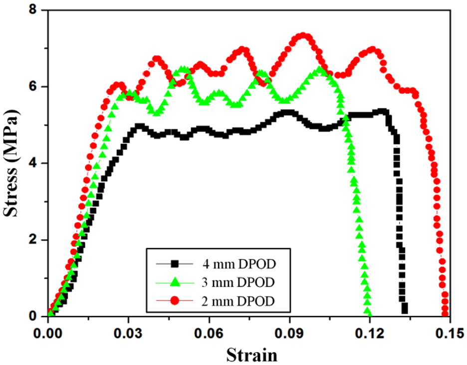
Stress-strain curve based on dynamic compression test on foam.
The test was performed for the specimens produced at 2, 3, and 4 mm hole diameters with double pass in opposite direction. The stress-strain is observed in impact testing shows the foam developed at different hole diameter has different properties. It was found that the foam developed at 2 mm hole has highest stress required for deformation as well as higher strain. The foam developed at 4 mm hole requires less stress for deformation and strain is also lower. The foam developed at 3 mm pin diameter requires less stress in deformation than the 2 mm hole foam. This is due to the fact that the relative densities are affected by the hole diameter. Also, it is observed that the uniformly distributed foam has better strength with lower strain.
The developed foam has also been tested for impact energy absorption with time. The energy absorbed along with the time (ms) is shown in Figure 17. It is found that that energy absorption is related to the foam density. As the relative density increases the foam requires high energy for deformation. The distribution of pores and pores size also affect the energy density same as in the static compression test. The foam with higher relative density at 2 mm diameter hole with single pass and double pass in same direction shows high energy for deformation. Similarly, foam developed at 4 mm diameter shows lower energy for deformation in all cases. The foam developed at 3 mm diameter hole shows moderate energy absorption during impact testing.
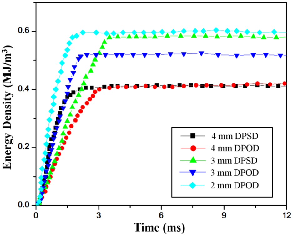
Energy versus time curve based on dynamic compression test on foam.
The energy absorption during impact testing is depends on the size of pores and its distribution. 33 The uneven distribution of pores in foam structure causes variation in wall thickness of cells which may causes variation in the load required for deformation. 37 While the uniformly distributed pores have almost equal wall thickness which leads to lower energy to fracture. Also, as the size of pores increases the wall thickness reduces which again reduces the energy required for deformation. Thus, a balance in the pores size and the wall thickness is required for a moderate energy absorbing capacity of foam structure. This term can also be referred as the relative density for a uniformly distributed foam structure. As the foam structure has uniform structure the energy absorption is uniform due to continues deformation of cell wall and showing better impact properties. 36
Conclusion
Successful AA2219-Y2O3 composite foam has been developed by using FSP. The developed foam has different relative densities. The relative densities of the foam directly related with the hole diameter and number of passes. Based on the characterization of the foam the following conclusion can be drawn from this research.
Underwater FSP can be used for development of AA2219-Y2O3 metal matrix composite foams using TiH2 as a foaming agent and Al powder as a thickening agent.
The current foam has fine pore size (0.7–2.7 mm) for the relative density ranges from 0.1 to 0.78.
The foam developed at 4 mm holes has better mechanical properties.
Increasing number of passes improves the static and dynamic compression behavior of developed foam.
Reversing the direction of tool rotation in different passes improve the distribution of TiH2 particles which improves the distribution of pores and reduces the pore size.
The second region of the static compression test shows longer range with uniformly developed foam.
The dynamic compression test shows higher relative density foam requires large forces for deformation.
Footnotes
Declaration of conflicting interests
The author(s) declared no potential conflicts of interest with respect to the research, authorship, and/or publication of this article.
Funding
The author(s) received no financial support for the research, authorship, and/or publication of this article.