
Abstract
TC4, which is one of the most widely used titanium alloy, is frequently used in biomedical field due to its biocompatible. In this work, selective laser melting (SLM) was used to manufacture TC4 parts and the printed parts were heat-treated using laser rescanning technology. The experimental results showed that laser rescanning had a high impact on the quality of SLMed part, and a different performance on wear resistance can be found on the basis. It can be seen that the volume porosity of the sample was 7.6 ± 0.5% without using any further processing technology. The volume porosity of the sample processed using laser rescanning strategy was decreased and the square-framed rescanning strategy had a relative optimal volume porosity (1.5 ± 0.3%) in all these five samples. With the further decreasing of volume porosity, the wear resistance decreased at the same time. As its excellent bio-tribological properties, the square-framed rescanning may be a potential suitable strategy to forming TC4 which used in human body.
Introduction
With the increasing demand on biomedical applications, TC4, which is short for Ti6Al4V, has attracted an increasing attention due to its lightweight, super plasticity, great formability and excellent resistance. 1 This material also shows an excellent compatible to human body and has already been used for artificial skeleton, vascular stent and so on. As the high hardness and low thermal conductivity of TC4, traditional process technology is hard to meet the need for manufacturing biomedical TC4 applications with small size and high resolution. 2
Selective laser melting (SLM), which is known as one of additive manufacturing (AM) techniques under powder bed fusion, has attracted an increasing attention due to its ability to print metal parts. 3 The powder laying roller pushes the powder evenly onto the worktable, which is convenient for laser processing. Designed and generated STL files stored in computer system, so that the laser scans according to a predetermined path. The powder in the recovery system is taken out for follow-up use and whole forming process is carried out in inert gas, as shown in Figure 1.
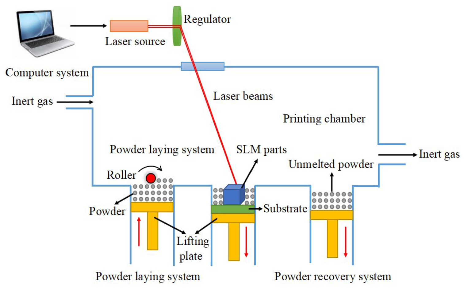
Schematic diagram of the selective laser melting machine.
Many researchers now show great interests in this technology. Kurian and Rakeshnath, Cheng and Chou, and Erik et al. studied the mechanical properties of the parts manufactured by TC4 alloy.4–6 They found that process parameters, such as scanning strategy, laser power, scan speed can highly affected the porosity of the printed parts which can further affect the mechanical properties. As for other metal alloys, such as weathering steel, Ni-Ti structure, Inconel-718 alloy, Ni/Fe-based superalloy, and some other Al alloy have also been studied by some other researchers.7–10 Olakanmi et al. studied aluminum alloy powder. 11 The process parameters were changed to optimize the microstructure of the parts and different properties of the printed parts can be found in this work.
Indeed, some work was also done on surface quality of the printed parts. They found that laser power, scan speed and their combined interaction can highly affect the surface quality of the printed part. 12 These parameters can affect the surface tension resulting a shear force exerting on the liquid surface. This phenomenon was caused by the different surface temperature between laser beam and solidified zone due to the motion of the laser beam. Mumtaz and Hopkinson has done a series of experiments to study the effect of process parameters on the formation of surface roughness. 13 It confirmed that many parameters, like laser power, scan speed and layer thickness, had specific influence on both top and side surface roughness. Wang et al. found that scan power and scan speed has a combined effect to determine scan track characteristics and it is crucial for achieving a better surface quality of SLMed parts. 14 Tian et al. has systematically researched the influence of processing parameters on surface roughness in Hastelloy X alloy. 15 Laser power, scan speed, layer thickness and sloping angle of a surface were varied to understand their effects on surface roughness. A low scan power of 200 W and a high scan speed of 3000 mm/s was found to give the best down-skin roughness of 15 μm.
Researchers are now trying to optimize the property of the TC4 alloy using heat-treatment. Khorasani et al. tried to optimize the tensile strength of the printed TC4 part using heat-treatment and found that the process parameters can significantly change the property. 16 Xiao et al. found that the process parameters of the heat-treatment can affect the microstructures and mechanical properties of the TC4 part. 17 Nicoletto et al. found that the fatigue behavior was highly affected by the temperature used in heat-treatment. A significant difference can be seen on the testing results. 18 Although a quite significant improvement can be found on the samples processed using traditional heat-treatment, this technology needs extra instruments and time for this process. Due to this fact, laser rescanning is now considered as a promising technology to treat the printed TC4 part. This technology has been studied by some researchers in recent years. Vaziri et al. found that the tribological behavior of the Al alloy has been modified using laser rescanning technology. 19 Griffiths et al. changed the laser rescanning parameters and found that the grain microstructure was of Al-Mg-Zr alloy changed accordingly which was considered as the reason why laser rescanning technology was able to modify the property of the printed part. 20 Vaithilingam et al. studied the surface chemistry of the SLMed TC4 alloy using laser remelting and found that the surface treated with non-skin scanned and skin scanned strategies were significant different compared to forged material. 21 Yasa et al. studied the density, surface quality and microstructure of the printed 316L using laser remelting. It can be seen that an almost fully dense 316L part can be produced using laser remelting. 22
From the illustration given above, it can be found that laser rescanning technology is an effective method to optimize the property of the printed parts. Nevertheless, compared to the traditional heat-treatment, whether laser rescanning technology showed a further improvement on the property of the printed part. So in this work, the printed TC4 samples were treated using traditional heat-treatment and laser rescanning methods. Considering the characteristics of human bones, friction behavior were taken into account to evaluate the property of the samples due to the fact that it can highly affect the service life of the human bones. As volume porosity of the printed parts showed a significant impact on the friction behavior, it should also be studied in this work. In view of the actual working condition, friction behavior of the TC4 parts were tested in simulated body fluid (SBF) atmosphere due to its widespread use in biomedical.
Materials and instrument
TC4 powder provided by Shenzhen Minatech CO., LTD, China was used in this work as the raw material. As the powder size and flowability of the raw material did not meet the experiment need, ball milling was used to further increase the property of the powder. Ball milling machine was supplied by Across International CO., LTD, USA and 3 mm agate ball was used here. The rotation speed was set at 800 rpm and each direction (clockwise and anticlockwise) rotated 45 min. After that, milled powder was put into the tube furnace to dry. One thing should be noted that as TC4 is easy-oxidization metal powder, argon was pumped into the furnace in this process as the protective gas. The temperature of the furnace was set at 150°C with an increasing rate of 3°C/min and kept for 50 min. The property of powder before and after processed was shown in Table 1.
The relative information about the TC4 powder before and after process.
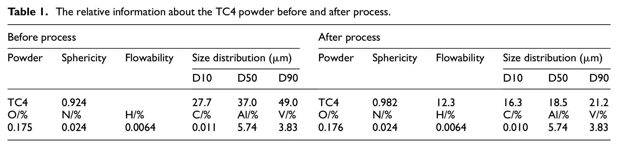
It can be found that the chemical composition of the powder showed little change while the sphericity, flowability and diameter of the powder showed an improvement compared to the unprocessed powder.
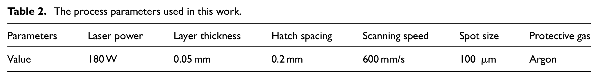
Process parameters used in this work were shown in Table 2, small cubes with a dimension of 12mm×10mm×5mm was formed by printing instrument FS291M, Farsoon, China. The heat-treatment parameter was selected at 850°C for 2 h (where, the unprocessed sample was named as sample 1, heat processed sample as sample 2) which was considered to have the best effect according to the previous study. 23 The laser rescanning strategies selected in this work were single-direction rescanning strategy (sample 3), Z-shape rescanning strategy (sample 4), and square-framed rescanning strategy (sample 5) which were considered as the most commonly used scanning strategies as shown in Figure 2. As shown in this figure, the black line indicates the initial scanning path, the rescanning path showed by red line which same as the initial scanning. We have studied the effect of above three different scanning strategies on the surface quality, structure, and dimensional accuracy of formed parts, and obtained some results, this follow-up study is used to improve our accumulation of different scanning strategies.1,24
The process parameters used in this work.
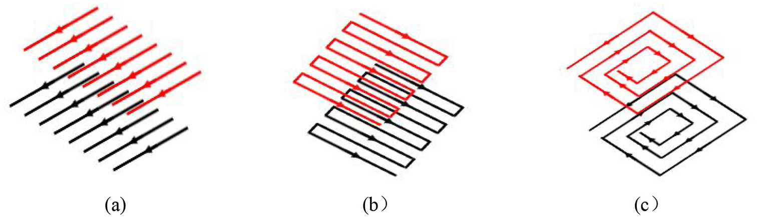
Laser rescanning strategies: (a) single-direction, (b) Z-shape, and (c) square-framed.
X-ray diffractograms (XRD) Bruker D8 Advance XRD machine (Bruker, Germany) using CuKa radiation at a 2θ range from 10° to 90° with a fixed scan rate of 2.0°/min was also used to check the chemical composition of the printed parts to better illustrate the phenomenon.
Volume porosity of the printed parts were measured using drainage method. Metallurgical microscope (DM2700M, LEICA, Germany) and white light interference profilometry (MFP-D, RTEC, USA) were also used to observe the voids clearly. Residual stress was measured here using blind-hole method with 1mm drilling depth by multi-point residual stress measurement and analysis system (JHMK, Nanjing Juhang Technology, China). The diameter of drilling hole was also 1mm in this work and each sample drilled six holes. Average value was calculated to prevent the error happened on the measuring process.
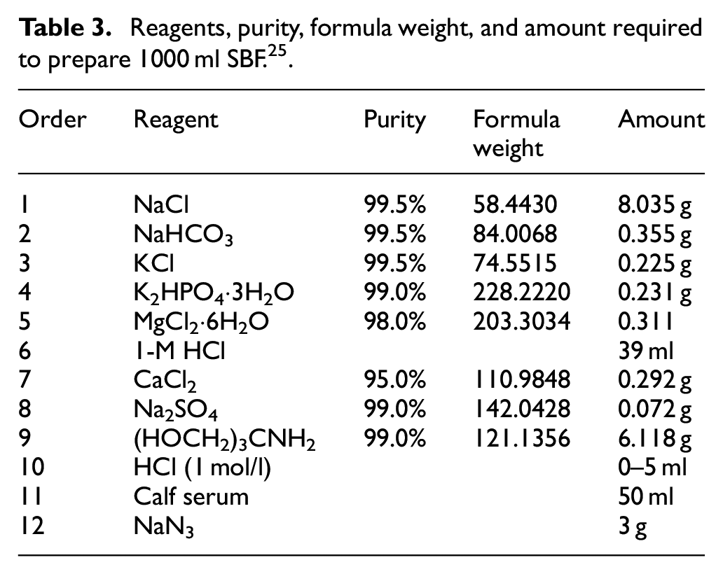
As wear resistance was one of the most important factor to affect the service life of the artificial bone, Tribometer (MFT-5000, RTEC, USA) was used in this work. P1600 mesh abrasive paper was used to rough grinding, following with fine grinding by W5 abrasive paper until the specimen reaches almost the same surface roughness before wear test. The load applied on the sample was 15 N with a frequency of 1 Hz, which consistent with the normal pressure on human body. 25 The reciprocating sliding distance was 10mm and the duration time was set to 1800 s. The experiment was repeated three times, and the average value was used as the data of this paper. The Si3N4 with a diameter of 6 mm ball was used as the friction ball in this work. Surface morphology of wear scar was tested by SEM and EDS (su1510, Hitachi, Japan). All tests were carried out in SBF at body temperature (37 ± 0.2°C); the pH value of solution was adjusted to 7.4 (normal pH value of human body fluid lies between 7.35 and 7.45). The compositions of the SBF were listed in Table 3.
Reagents, purity, formula weight, and amount required to prepare 1000 ml SBF. 25
Results and discussion
XRD characterization
To better illustrate the formation process and quality of the printed parts, XRD was used to study the component of the metal structure as shown in Figure 3. It should be noted that this is the XRD of sample 1. The XRD of the other four samples is the same as this one, therefore only the XRD of sample 1 is shown in this chapter. It can be seen that α-Ti made up the largest portion of the printed part. Its peak was located at around 34°, 36°, 39°, and 53° separately with the highest intensity at 39°. According to the report, α-Ti is considered to have better yield strength and ultimate tensile strength compared to wrought Ti and that is the reason why some SLMed TC4 parts showed better property compared to wrought parts. 26 As for Al and V, they can be found in Al2Ti3 and CTi0.42V1.58 which were located at around 34°, 36°, 39° and 34°, 39°, 53°, 63°, 73°, 77°, 78°, respectively. As little difference of the metal component was found on the printed samples, it means that these different rescanning strategies, indeed, has no obvious influence on the structure of components.
XRD of the TC4 parts.
Volume porosity
Volume porosity of the parts was measured using drainage method. First, weigh the samples using analytical balance in dry condition, labelled as M. Second, put some deionized water into the graduated cylinder and read the scale on it, labelled as V0. Then, put the sample into the graduated cylinder and read the scale again, labelled as V1 as shown in Figure 4. At last, calculate the volume porosity using the following equation 25 :
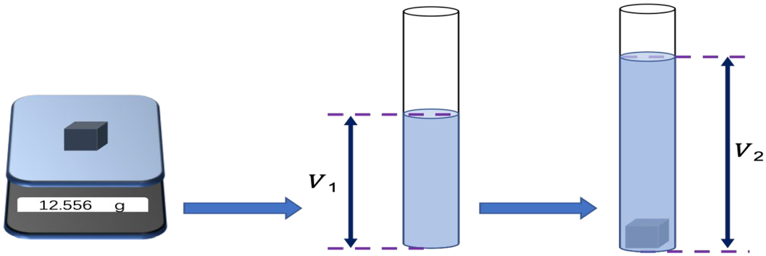
Schematic diagram of the drainage method.
where, θ is the volume porosity of the sample; ρ is the density of the wrought TC4.
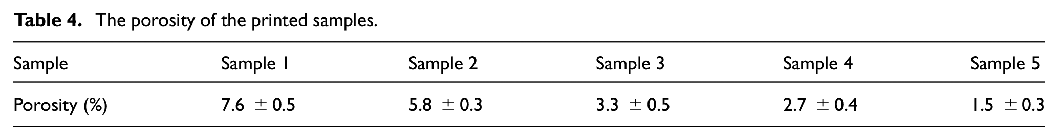
It can be seen from Table 4 that the porosity of the untreated sample was higher than the other four samples while the sample processed by traditional heat-treatment method was still a little higher compared to the samples treated using laser rescanning strategies. As for the samples treated using laser rescanning strategies, the square-framed scanning strategy showed a relative optimal performance compared to the other two rescanning strategies. The formation of voids was mainly caused by the splash of powder in the printing process and residual stress led to the bending deformation of the sample which further increased the dimension of voids. 6 The traditional heat-treatment method can decrease the porosity of the samples due to the release of residual stress of the samples. Although this method cannot prevent the formation of voids, it still had an effect to control the dimension of the voids. As for the laser rescanning strategy, it can not only release the residual stress to control the size of voids, but also melt the bonded powder and molten pool positions which was higher than the process layer. It led to the formation of liquid-state metal which was likely to fill in the small voids on the layer surface.
The porosity of the printed samples.
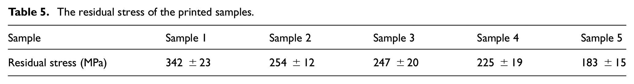
To verify the explanation given above, the residual stress was tested using the residual stress measurement instrument and the testing data was shown in Table 5. It can be seen that the residual stress of the untreated sample was the largest. The value of the samples treated by single-direction rescanning strategy and Z-shape rescanning strategy compared to the samples treated using traditional heat-treatment method decreased but not much. Apparently, the residual stress of the sample treated using square-framed rescanning strategy was the lowest in all these five samples. This result confirmed the explanation given above.
The residual stress of the printed samples.
Scanning electron microscope (SEM) was also used here to check the surface morphology of the printed samples as shown in Figure 5. Figure 5(a) to (c) was the untreated sample surface, traditional heat-treatment sample surface and the square-framed laser rescanning sample surface with 200× magnification. It can be found that the molten path of the untreated sample and the sample treated using traditional heat-treatment was much clearer compared to the sample processed by square-framed laser rescanning strategy. It was mainly caused by two reasons. The first one was the mainly caused by the melting of the convex peak of the surface in this process. Another reason was the change of the temperature field of the molten pool. The temperature gradient of the molten pool had a descending trend after laser rescanning which caused a lower molten pool convection in the forming process and the square-framed scanning strategy had lower temperature gradient in all these three scanning strategies.1,24,27 This further verified the above explanation.
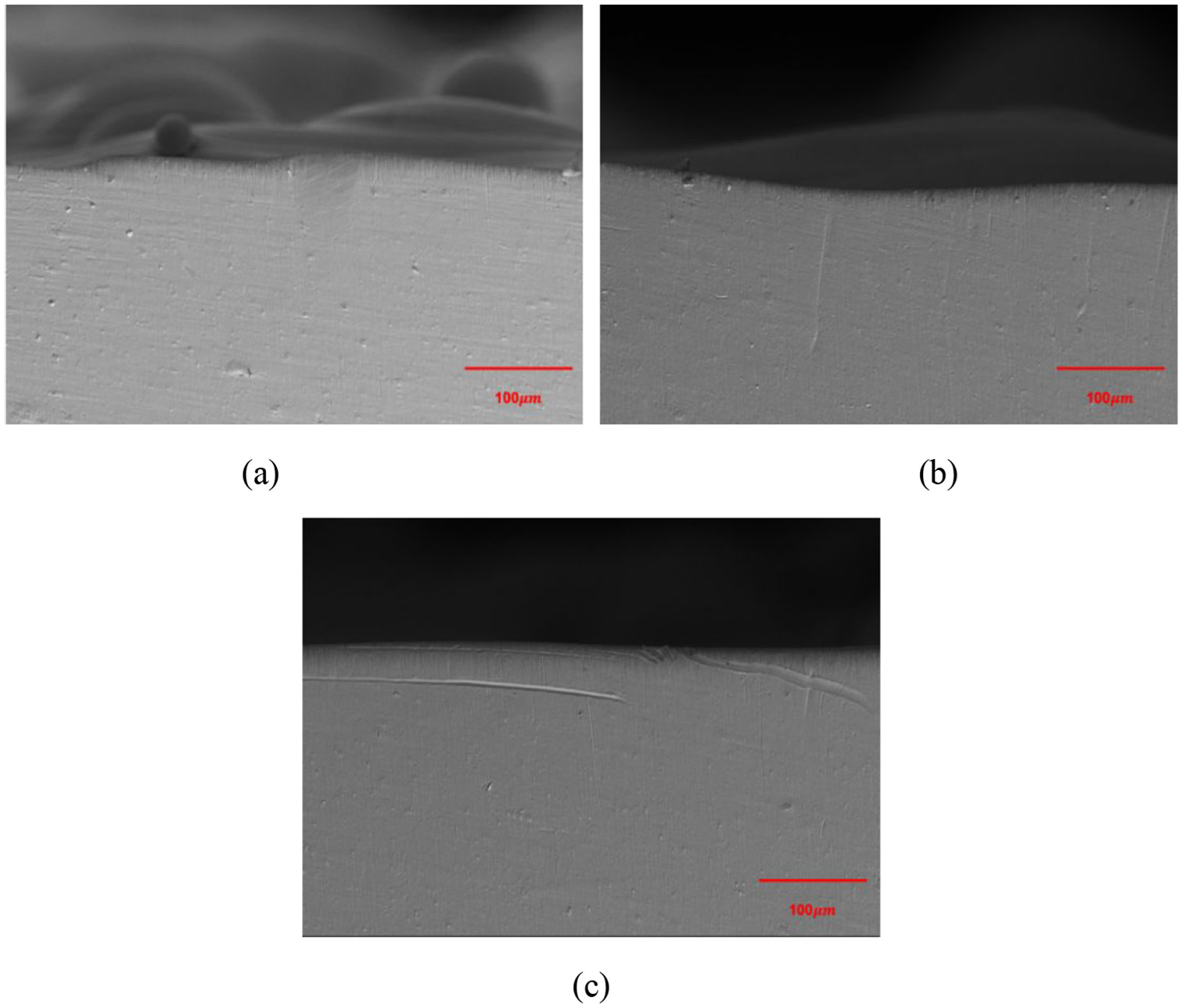
The surface morphology of samples: (a) untreated sample, (b) traditional heat-treatment sample, and (c) square-framed laser rescanning sample.
The morphology of the voids was captured using metallurgical microscope. As the dimension of voids is hard to detect directly using metallurgical microscope, white light interference profilometer was also employed in this section. Figure 6 showed the voids of untreated sample, traditional heat-treatment sample, single-direction laser rescanning sample, Z-shape laser rescanning sample and square-framed laser rescanning sample. It can be noticed that obvious large and irregular voids can be found on the untreated sample. Compared to Figure 6(a), the voids in Figure 6(b) showed a reduction on dimension while the amount did not show any improvement. As for the voids shown in Figure 6(c) to (e), both the dimension and amount of the voids showed an improvement compared to the voids shown in Figure 6(a) and (b). According to the SEM, the morphology of the samples after laser rescanning treatment is improved significantly. Furthermore, the voids of the sample treated by square-framed laser rescanning showing fine and evenly distributed voids, which indicates that square-framed laser rescanning may be an effective way of forming TC4 parts applied in human body.
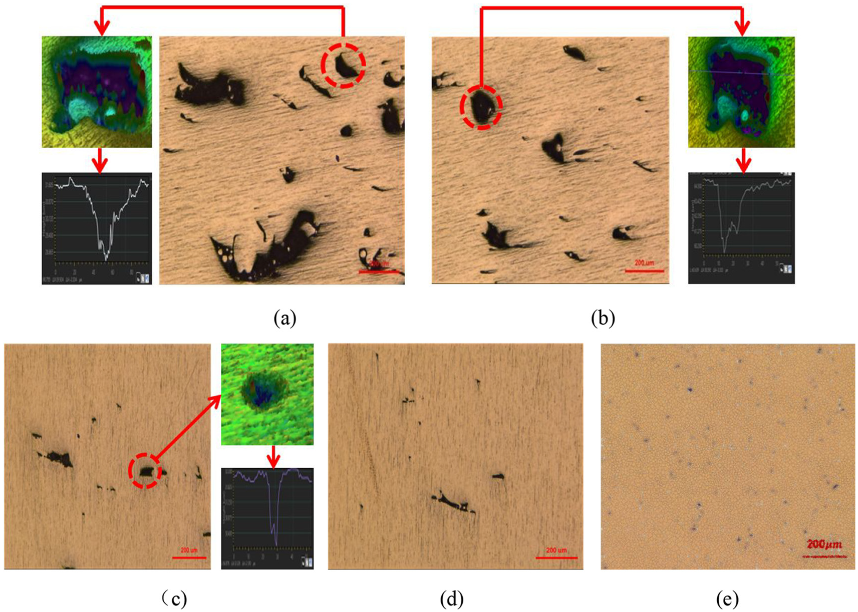
The voids on the samples: (a) untreated, (b) traditional heat-treatment, (c) single-direction, (d) Z-shape, and (e) square-framed.
Wear resistance
Friction and wear test is an important index to measure the properties of samples.28,29 As TC4 has great biocompatible property which is now frequently used as human implants, a study on the performance of wear resistance in SBF atmosphere is quite important and necessary. The friction coefficient of samples was shown in Figure 7(a). It can be found that the friction coefficient was ranked in the descending order from sample 5 to sample 1. To further clarify this phenomenon, average friction coefficient and wear rate were calculated and shown in bar chart in Figure 7(b). It can be seen that the average coefficient value of sample 5 and sample 4 was 0.3382 and 0.3065, respectively, which were a little higher than other three samples. While the differences between sample 3 and sample 4 was not particularly obvious, sample 5 has a relatively minimum friction coefficient. Normally, the increasing friction coefficient leads to the higher wear capacity which means the lower wear resistance. 27 Meanwhile, the results of wear volume verified our analysis given above, sample proceed via square-framed laser rescanning accompanied with excellent wear resistance.
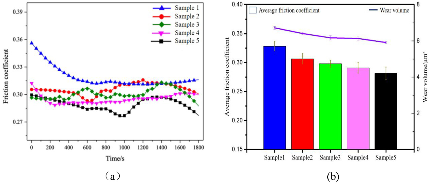
Wear test: (a) friction coefficient and (b) average friction coefficient and wear volume.
The wear morphology of the printed samples was shown in Figure 8. The ploughing and debris can be clearly seen. TiO2 flaked during wear process resulted to the ploughing wear, which was considered as the main wear mechanism shown in Figure 9. Oxidation erode can also be found in this process shown in this Figure. To give a more intuitive illustration, EDS was used here to study the content of the element on some typical characteristics. The element content of the crystal particle near the ploughing wear was the mixture of SBF fluid and wear debris. As for the surface of the substrate, it was mainly consist of Ti and its oxide. SBF solution crystallizes and some crystal can be seen on the surface of the sample as shown in Figure 8.
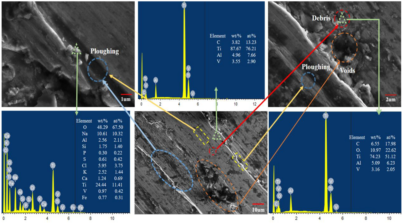
Surface morphology of wear scar tested by SEM and EDS.
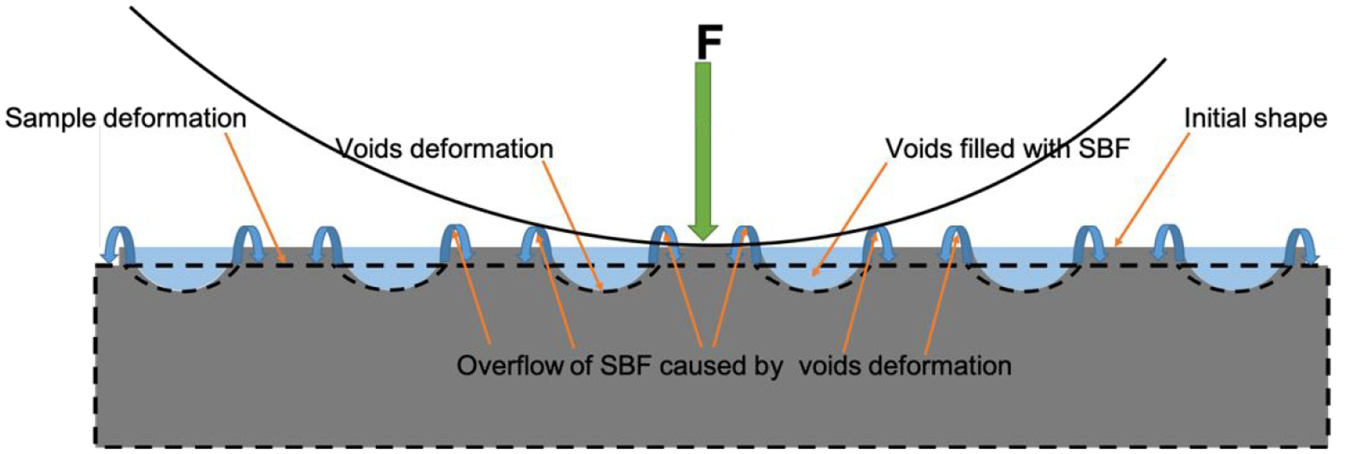
Schematic diagram of the wear behavior of the porous part.
The different performance of these five samples on wear resistance was mainly due to the porous structure on the surface of the printed parts. Voids with larger openings on the surface were able to hold more SBF as lubricating fluid to reduce the ablation loss. Tiny voids with greater depth can also provide some SBF as lubricating fluid, although the amount was not as sufficient as the voids with larger openings. However, a larger number of tiny, regular and evenly distributed voids on the surface demonstrate better wear resistance performance. 25 Moreover, the SBF stored in voids can also provide opposite force to further increase the wear resistance. That was the reason why sample 5 showed a better performance on wear resistance.
To sum all these testing results up, including volume porosity and wear resistance, it can be found that Sample 5 treated under square-framed rescanning strategy showed better volume porosity compared to other four parts, its wear resistance was, the lowest in all these five samples simultaneously. Moreover, the morphology of the voids showed that voids with tiny, regular and evenly distributed showed a more significant influence on the increasing of wear resistance in SBF atmosphere compared to those large and irregular voids.
Conclusion
In this work, the effect of laser rescanning strategy was systematically studied and the performance between the traditional heat-treatment and laser rescanning strategy was compared. It can be seen that although traditional heat-treatment showed a better ability to relief the residual stress of the printed part, laser rescanning strategy had a better performance on the reduction of volume porosity of the printed parts. In all the rescanning strategies, sample 5 which was printed using square-framed rescanning strategy showed the best performance as the porosity of the printed part was able to reach 1.5%. A similar conclusion can be made on the wear resistance test. As its excellent bio-tribological properties, the square-framed rescanning may be a potential suitable strategy to forming TC4 parts used in human body.
More work will be done concentrating on optimizing process parameters and study the interaction of rescanning process parameters. Besides, explore the feasibility of improving the performance of TC4 samples by spacer layer rescanning and the impact on cycle time of layer rescanning is equally important.
Footnotes
Declaration of conflicting interests
The author(s) declared no potential conflicts of interest with respect to the research, authorship, and/or publication of this article.
Funding
The author(s) disclosed receipt of the following financial support for the research, authorship, and/or publication of this article: This study was supported by the Additive Manufacturing Products Supervision and Inspection Center of Jiangsu Province, Wuxi Institution of Supervision & Testing on Product Quality, Wuxi, China.