
Abstract
In this study, a new methodology is considered for determining the rotational senses (clockwise or anti-clockwise) of a workpiece during the hydroabrasive disintegration of rotating samples. The rotational directions are taken with respect to the position of the abrasive jet, that is, keeping it on the right side of the rotating workpiece when viewed from the free end in the cartesian coordinate system. Measurements were carried out for diameter deviation, material removal rate and surface roughness as a response to machining parameters such as traverse speed, workpiece rotation direction and abrasive grain. Final diameter of the workpiece (10.28–14.12 mm), material removal rate (1154–3936 mm3/min) and surface roughness (6.65–25.43 µm) values increase with increasing value of traverse speed (5–25 mm/min) using anti-clockwise rotation with Australian garnet abrasive grains. ANOVA analysis of the responses shows that traverse speed (p = 0.000) is a statistically significant parameter for predicting all the machining responses. Abrasive type and rotational direction were statistically significant for determining diameter deviation (p = 0.017, 0.006) and material removal rate (p = 0.000, 0.000) but insignificant for surface roughness (p = 0.373, 0.367). Scanning electron microscopy provided information on the surface morphology, depicting the characteristics of the disintegrated surface. Disintegrated features, like peak and valley formations, craters, holes, cutting traces and embedded abrasive particles on the surface were observed.
Introduction
Abrasive water jet turning (AWJT) 1 is a modern, unconventional materials-processing technology where the surface of a rotating workpiece is eroded by the disintegrating effect of a high-speed (700–800 m/s) abrasive-laden water jet. As a result, the target surface can have a corrugated nature due to plastic deformation.2,3 For this reason, research in this area is focused on maintaining the correct correspondence between dimensional accuracy (ΔD%), material removal rate (MRR), and the quality of the resulting machined surface (Ra and Rz). 4 Many research experiments have been carried out in this field of technology and are still producing new results.5–7 These experiments aim to find the most effective conditions that can lead to exploiting the maximum potential of this technology. By carrying out these experiments, new knowledge is gained by considering the interactions of the technological parameters used during the investigation. There are some technological parameters by which the experiment can be controlled.8–10 These include the liquid pressure p [MPa], feed rate v [mm/min], spindle speed n [min−1], cutting depth ap [mm], nozzle diameter d [mm], the distance of the nozzle from the disintegrated surface z [mm], material type, abrasive feed rate ma [g/min], abrasive grain size [Mesh] and the abrasive type.
In 1987, the first study focusing on AWJT technology was performed by Hashish. 11 The potential of using this technology by changing various parameters and materials, such as aluminium and its composites, was investigated experimentally. It also highlighted the importance of this technology and its usefulness. Zohor and Zahourkari 12 critically investigated the effect and influence of the position and tilt of the nozzle on the resulting accuracy of the diameter obtained during the AWJT process, something which was previously neglected. Mathematical expressions to describe its determination, in addition to the parameters, were derived. Zhog and Han 13 investigated processing glass materials using AWJT. They aimed to examine the surface structure obtained when using specified cutting parameters, with subsequent comparison to conventional glass processing. AWJT has also found potential in processing special materials. A specific study of such materials was conducted by Kartal et al. 14 optimising the cutting parameters (v, ma, p, d, and z) for machining aluminium alloy Al6082 T6 and their influence on the surface roughness and its macrostructure. Carach et al. 15 investigated disintegrating Monel K-500 with AWJT. The quality of the resulting surface and the effects of the interactions on the material removal rate were examined. The main parameters affecting the material removal rate and the resulting roughness parameter were v and ma. Furthermore, the main parameters that influenced the course of disintegration were spindle speed and abrasive grain size. Kartal et al. 16 focused on optimising the processing of low-density, polyethene materials with AWJT. Optimal parameters were found to make this processing process more efficient. The Taguchi method was used for the optimisation. Uhlmann et al. 18 carried out comparative study between conventional turning and AWJT using γ-TiAl alloys. Results showed less mechanical effected (hardness penetration) material surface with AWJT as compared to conventional turning having similar MRR. Hloch et al. 5 conducted AWJT of Titanium workpiece to observed the effect of traverse speed on surface roughness of the machined surface. However, no rectilinear trend of Ra, Rq and Rz with traverse speed was observed. Table 1 shows some of the previous experiments, indicating the parameters that were investigated and determined.
Previous experimental studies.
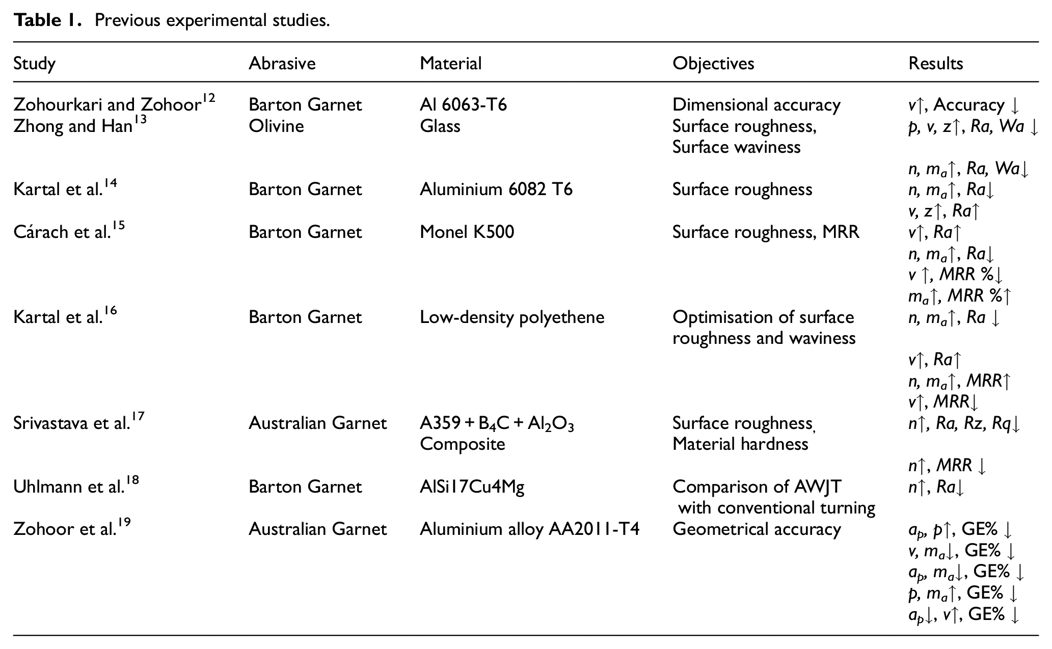
Most previous research dealt with studying the influence of technological parameters, such as p, v, z, n and ma. 20 However, not many studies have focused on the type of abrasives and the workpiece rotation direction with respect to the jet. The properties of the abrasives (such as cleavability, transparency, gloss and hardness) can directly influence the machining process and, therefore, the resulting surface quality and dimensional accuracy of the workpiece. 7 Table 1 lists some experimental tests that show the absence of variation in the type of abrasive particle used during the experiments. Using a suitable abrasive during disintegration can be advantageous when processing a specific material, from a technological and economic point of view. Selecting a suitable abrasive type for a targeted material (particularly in the case of special materials) would bring economic advantages, as well as quantitative and qualitative benefits. 21 Moreover, the workpiece rotation direction influences the material removal process. 22 When considering the interaction of an abrasive particle with a rotating workpiece at an elementary level, opposing technological effects occur. Therefore, the technology should be understood from the point of view of different forces acting on the abrasive particle. 9
In some previous studies, rotation direction was termed as ‘away’ and ‘towards’ the abrasive jet, which is quite unintelligible since the motion of the jet is linear while the workpiece has rotational motion, which makes no sense if they are parallel and opposite. Therefore, to improve the evaluation procedures for performance analysis of response measurement, senses of rotational direction are termed clockwise and anti-clockwise in this study. The standard right hand cartesian coordinate system was used with the positive x and y axes towards the right side and upwards, respectively, viewing from the free end of the rotating workpiece. The clockwise rotation direction is represented by +ϕ and anti-clockwise by –ϕ (Figure 1). For the offset turning mode, the abrasive jet was moved towards the positive x-axis with a distance of Ri– ap from the centre. For the erosion model with a clockwise direction, the abrasive particles in the AWJ (va) travel parallel to the rotating workpiece surface (vw = ω−j.sinα), which lowers the relative velocity of the particles (vw– va). These cutting components tend to plough the material due to the parallel direction of the abrasive particles when compared to a particle stream anti-clockwise to the direction of erosion. In the anti-clockwise direction erosion model, the components of the cutting force act in the opposite direction, increasing the relative velocity (vw+va). This increases the interaction area and time between the particle and workpiece material, resulting in a higher MRR and a deteriorated surface finish.
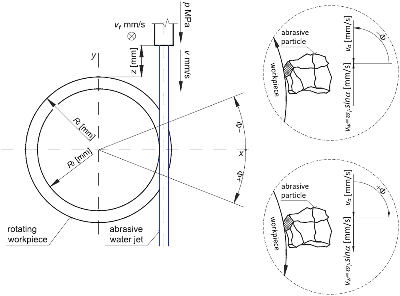
Comparison of the effect of the abrasive particles on the material surface: (a) clockwise and (b) anti-clockwise.
Therefore, in the present study, measurements of the final diameter (Df), MRR, Ra as a response to varying v (5–25 mm/min), the abrasive type (Australian garnet and olivine), and rotation direction (clockwise and anti-clockwise) was studied. The surface morphology of the disintegrated surface was investigated using SEM analysis.
Experimental setup
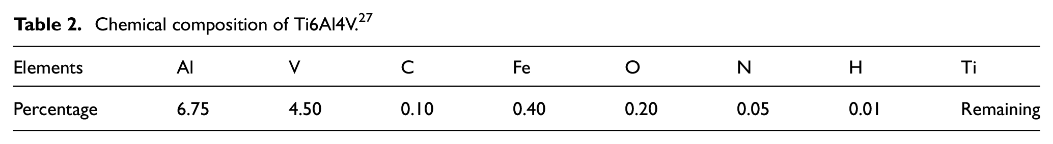
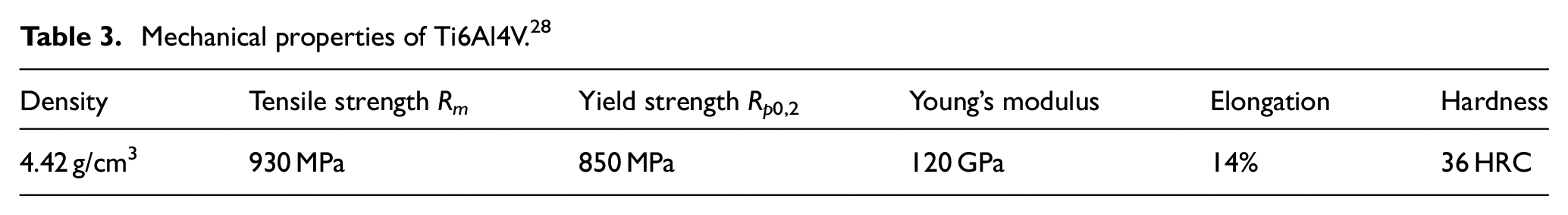
In the experiment, Ti6Al4V was used as the workpiece. Ti6Al4V is used in many areas requiring materials with significant resilience, durability and strength. 23 The application of this alloy is versatile, as its current use is concentrated in several areas of industry, such as aerospace, the automotive industry and shipbuilding. It is also widely used in medicine, especially where biocompatibility is an issue and direct contact with tissue or bone is required. The oil industry mainly applies this kind of alloy in the construction of fuel turbines. However, turning of Ti6Al4V using conventional methods due to low specific heat (580 J/Kg-K) and thermal conductivity (7.3 W/m-K), 24 results in higher machining temperature (>500°C). 25 At elevated temperature, work hardening of Ti6Al4V, occurs leading to generation of high machining forces. 26 Therefore, in this study AWJT of Ti6Al4V was performed due to the advantage of being cold machining process. The chemical and mechanical properties of Ti6Al4V are shown in Tables 2 and 3.
Chemical composition of Ti6Al4V. 27
Mechanical properties of Ti6Al4V. 28
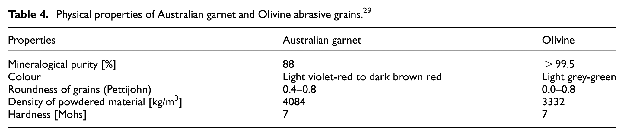
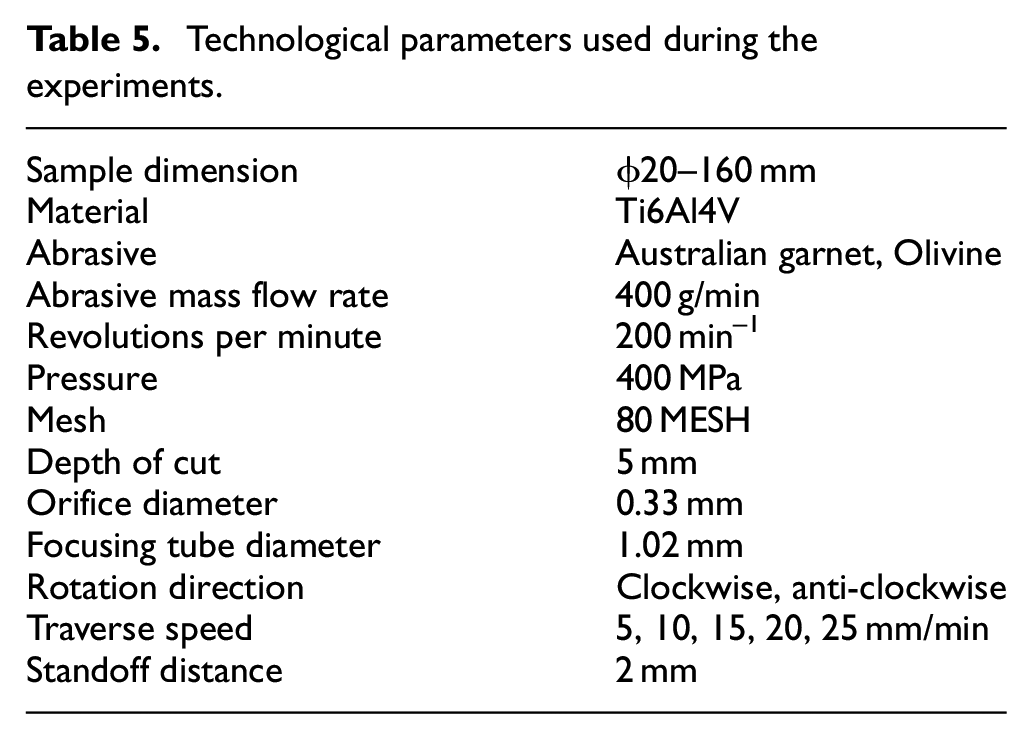
The equipment used in the experiment consisted of a PTV W2020-2Z-1xPJ, 2D XY table for abrasive water jet cutting. The system pressure was provided by a PTV 75–60 high-pressure pump with two intensifiers that could produce a maximum pressure of p = 400 MPa and a maximum liquid flow rate of 7.8 l/min. The sample clamping element was a 100 mm three-jaw chuck, whose maximum rotational speed was n = 500 min−1. Australian garnet and olivine abrasive grains were used for these experiments due to their practical use for machining materials in industries from efficiency and economic points of view. Figure 2 shows the surface morphology, specifically shape and size of the abrasive grains (Australian garnet & Olivine) used during the experiments. The properties of these abrasives are summarised in Table 4. The technological parameters used during the experiments were selected based on pilot experiments and are shown in Table 5.
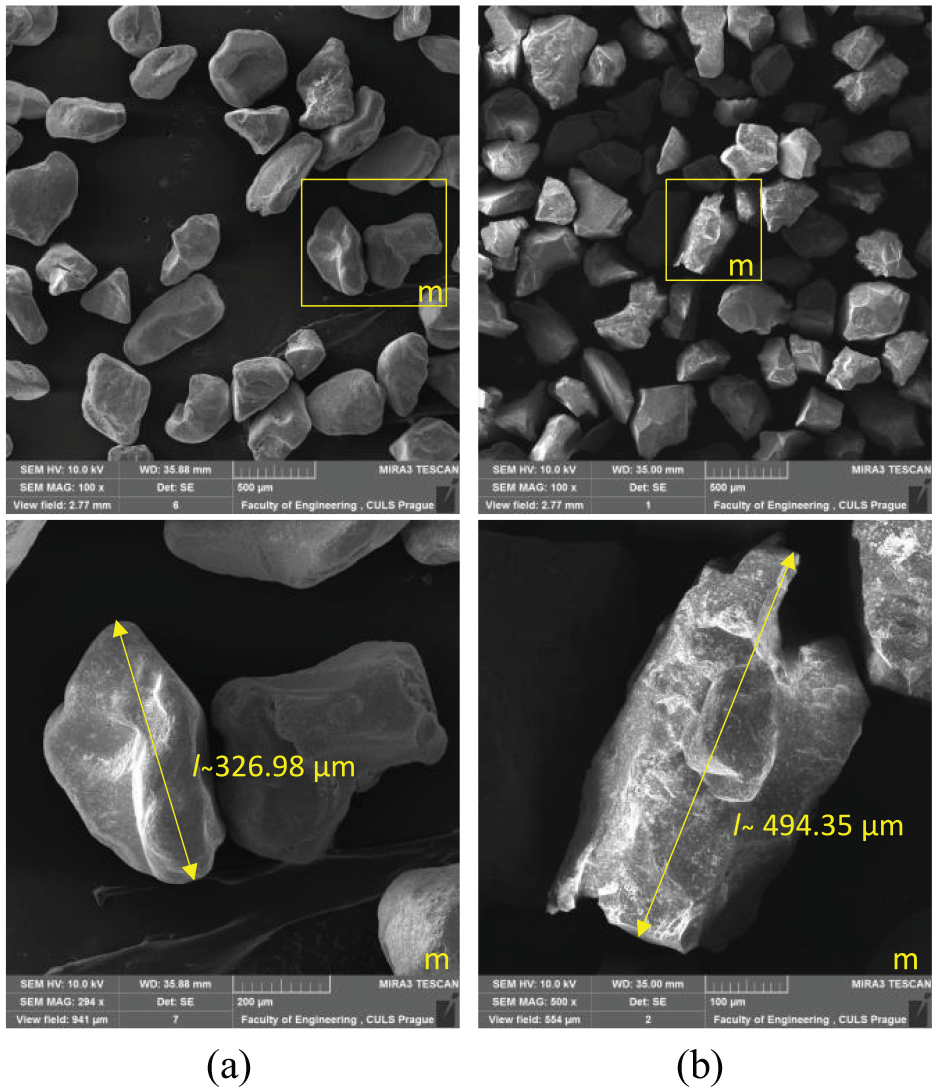
Abrasives used in the experiment (a) and (a-m) Australian garnet, (b) and (b-m) olivine.
Physical properties of Australian garnet and Olivine abrasive grains. 29
Technological parameters used during the experiments.
Experiments were carried out from the left-hand side of the sample with traverse speeds of 5 mm/min, increasing to 25 mm/min, and travelling a 10 mm distance at each speed. The relative rotational direction with the abrasive was kept in the clockwise mode. Subsequently, all five traverse speeds were then tested with an anti-clockwise interaction direction of the abrasive and workpiece. All ten experimental runs were carried out using Australian garnet. A new workpiece was then clamped, and the previous experimental runs were repeated in the same order using olivine as the abrasive particle (Figure 3).
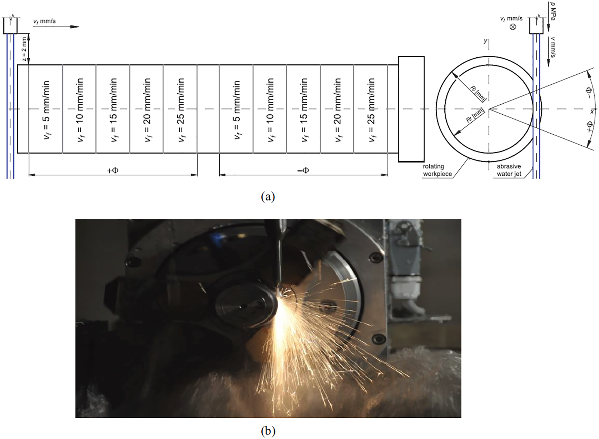
(a) Schematic outline of the experiment and (b) front view of the actual experimental setup.
After the experimental runs, five values of Df were measured for each section using a digital Vernier calliper (Make: Mitutoyo absolute digimatic, Model no. – CD 15DCX, Resolution – 0.01 mm). The material removal rate was calculated for each section using equation (1).
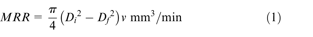
where
The resulting surface characteristics were evaluated using a MicroProf FRT profilometer. The measurements were performed at three measuring levels. The obtained values were imported into the SPIP 6.7.8 evaluation program, from which the obtained surface roughness parameters were generated for each investigated section. After surface structural measurements were made, the samples were examined using SEM. A TESCAN MIRA 3 GME with secondary electron detector and 10 kV acceleration voltage was used for capturing the surface morphology images.
Results and discussion
An experimental study of the hydroabrasive disintegration of a rotating Ti6Al4V blank was performed according to the technological parameters shown in Table 5. After the experiment, the cylindrical samples were examined. A total of twenty specimens, with the characteristics detailed in Figure 4, were created.
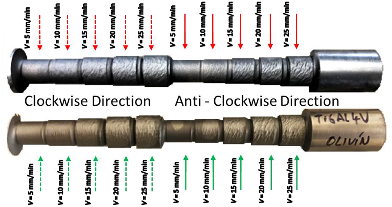
Disintegrated workpiece using clockwise and anti-clockwise rotation directions, with Australian garnet (upper) and olivine (lower) grains.
Final diameter (Df)
The final diameter of each section was measured using a digital micrometre. Fifteen readings for each section were recorded and their mean was plotted (Figure 5) and used for statistical analysis. The calculated Df for each run was Df = 10 mm (Di = 20 mm, ap = 5 mm) after the experimental run. The graph shows an increasing trend of Df with increasing v from 5 mm/min to 25 mm/min for all four technological variations. 30 At v = 5 mm/min, Df for all cases was nearly the same and closer to the calculated Df = 10 mm. This is attributed to the longer interaction time between the rotating workpiece and the AWJ, 12 sec/mm at v = 5 mm/min, compared to 2.4 sec/mm at v = 25 mm/min. This trend can also be explained by the form of the overlapping index ε, determined using equation (2).
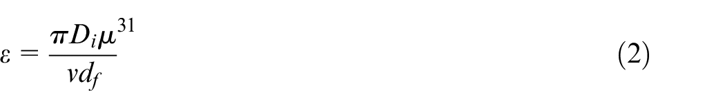
were Di is the workpiece diameter and df is the jet’s diameter. With increasing v, ε decreases, which decreases the overlapping time of the material surface with the abrasive jet. This trend (Figure 5) is similar to the study conducted by Yue et al. 32 which also concluded that a decrease in traverse speed increases the material removal capability of the abrasive jet. Additionally, the number of abrasive particles interacting with the surface decreases with increasing traverse speed from 5 mm/min (40 g/mm) to 25 mm/min (8 g/mm). With increasing v (5–25 mm/min), ΔD% also increases from 4.9 to 48.02% for clockwise and from 2.84 to 41.22% for anti-clockwise using Australian garnet grains. With olivine grains, ΔD% increases from 6.24 to 52.96% for clockwise and from 3.92 to 46.16% for anti-clockwise. The anti-clockwise material rotation direction ploughs more material from the rotating surface due to the increase in interaction time and the area between the abrasive grains and material surface. This increases the relative kinetic energy interaction between the jet and material surface, resulting in lower Df when keeping the other parameters constant (Df = 15.29 ± 0.0167 mm and 14.62 ± 0.027 mm for the clockwise and anti-clockwise rotation directions, respectively, using olivine). Olivine abrasive grains erode less material from the material surface due to their shape and physical properties compared to Australian garnet under the same technological conditions (Df = 14.80 ± 0.0526 mm and 15.29 ± 0.0167 mm for Australian garnet and olivine, respectively, in the clockwise rotation direction at v = 25 mm/min).
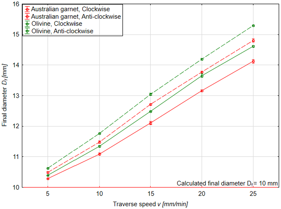
Variation of final diameter (Df) with variation of the technological parameters.
Material removal rate
The MRR was calculated using equation (1). The variation of MRR with increasing v from 5 mm/min to 25 mm/min is shown in Figure 6. At v = 25 mm/min, the jet travels 10 mm in 24 s compared to 120 s for v = 5 mm/min. This increased machining time for eroding the same amount of material lowers the MRR (1146.12±0.68 mm3/min compared to 3657.56 ± 15.51 mm3/min for 25 mm/min, using olivine in the anti-clockwise rotation mode). A lower Df (10.28 ± 0.0134 mm) is achieved at a lower traverse speed (v = 5 mm/min), representing higher material removal (2309.78 ± 1.09 mm3) (Figure 5). However, the time taken by the AWJ for removing material from the same section increases (120 s for v = 5 mm/min), decreasing the MRR (1154.89 ± 1.08 mm3/min) compared to v = 25 mm/min (3936.17 ± 37.04 mm3/min). This observation (Figure 6) is analogous to that in Zohourkarl et al. 33 in which, at a higher depth of cut, the MRR increases with an increase in traverse speed. The anti-clockwise rotation direction generates a higher value of MRR (3936.17 ± 37.04 mm3/min) compared to the clockwise direction (3550.18 ± 30.60 mm3/min). This is due to the interaction between the abrasive particle and the workpiece with higher relative velocity of (vw+va) as compared to (vw– va) for anti-clockwise and clockwise rotational direction, respectively (Figure 1), generating an increase in the cutting forces. Australian garnet, due to its sharp and irregular shape compared to olivine (Figure 2), ploughs the material efficiently and leads to a higher MRR, keeping other parameters constant (3936.17 ± 37.04 mm3/min and 3657.56 ± 15.51 mm3/min for Australian garnet and olivine, respectively, with the anti-clockwise rotation direction at v = 25 mm/min).
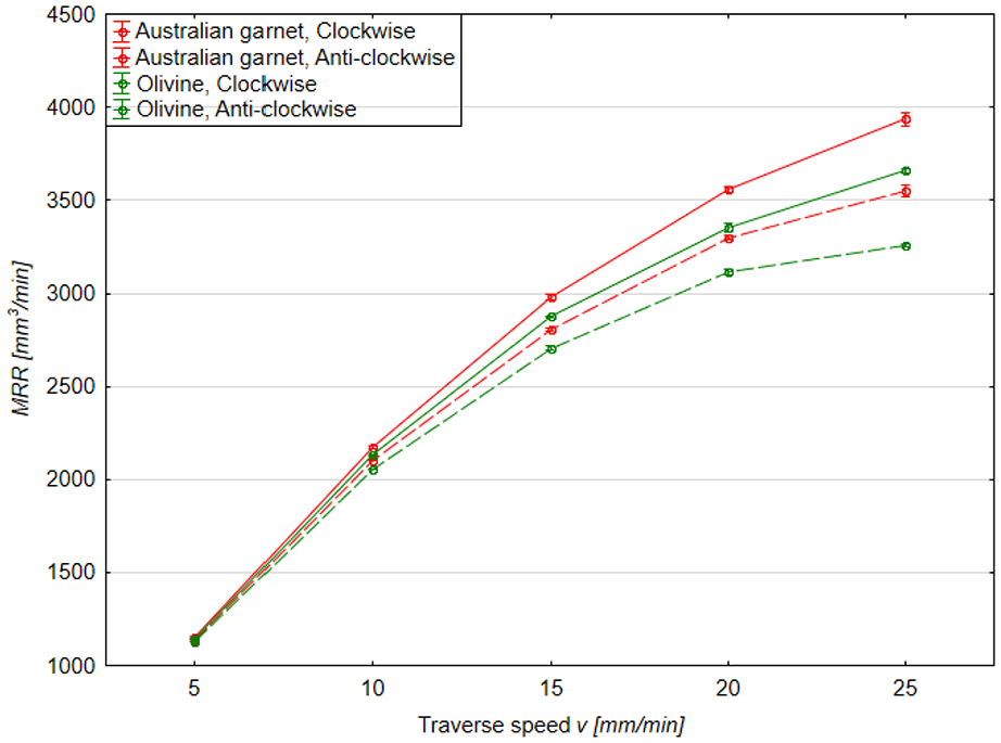
Variation of MRR with variation of the technological parameters.
Surface roughness
Figure 7 shows the changes in the surface roughness parameters due to changes in the process parameters. A similar trend was observed for both surface roughness parameters Ra and Rz with variation in the technological parameters. When the traverse speed increases from 5 to 25 mm/min, Ra and Rz increase due to the shorter interaction time between the abrasive particle and the material, causing a non-uniform disintegration. Moreover, with an increase in the traverse speed (from v = 5–25 mm/min), the overlapping of the disintegration area (equation (2)) ploughed by the abrasive decreases, leading to the formation of a thread-type surface on the circumference of the cylindrical sample. At the lower feed rate (v = 5 mm/min), more interaction time is available for the abrasive grains to erode the material surface uniformly and with more material removal. Australian garnet shows a lower value of surface roughness (Ra = 15.58 ± 2.36 µm) compared to olivine (Ra = 17.6 ± 3.67 µm) at a feed rate of v = 10 mm/min anti-clockwise rotation direction. This observation can be attributed to the breakdown of olivine into finer particles while passing through the mixing chamber, causing irregular grain shapes when exiting the nozzle. These grains cause an uneven surface finish compared to Australian garnet particles. For clockwise workpiece rotation, less interaction of the abrasive cutting edges takes place, leading to a finer surface finish. Whereas for anti-clockwise sample rotation, the cutting edges dug into the material more deeply due to the resultant forces acting on the abrasive particles (Figure 1), producing a roughened surface. An unusual observation was noticed at v = 20 mm/min for the olivine abrasive particles, where the Ra value for the anti-clockwise rotation direction (22.7 ± 2.87 µm) is lower than the clockwise rotation direction (23.87 ± 3.21 µm), with respect to the position of the abrasive jet. This observation could be attributed to the vibration induced in the rotating workpiece due to improper clamping of the workpiece or may be due to errors in the abrasive dosing mechanism. However, the most significant variable parameter in the study that affected the surface finish is the traverse speed. An approximately threefold increase in the roughness was recorded between v = 5 mm/min and v = 25 mm/min using olivine abrasive grains and a clockwise workpiece rotation direction. A similar trend of Ra variation (Figure 7) with the traverse speed was obtained by Kartal 34 in which Ra increased 16% while increasing traverse speed from 10 to 25 mm/min.
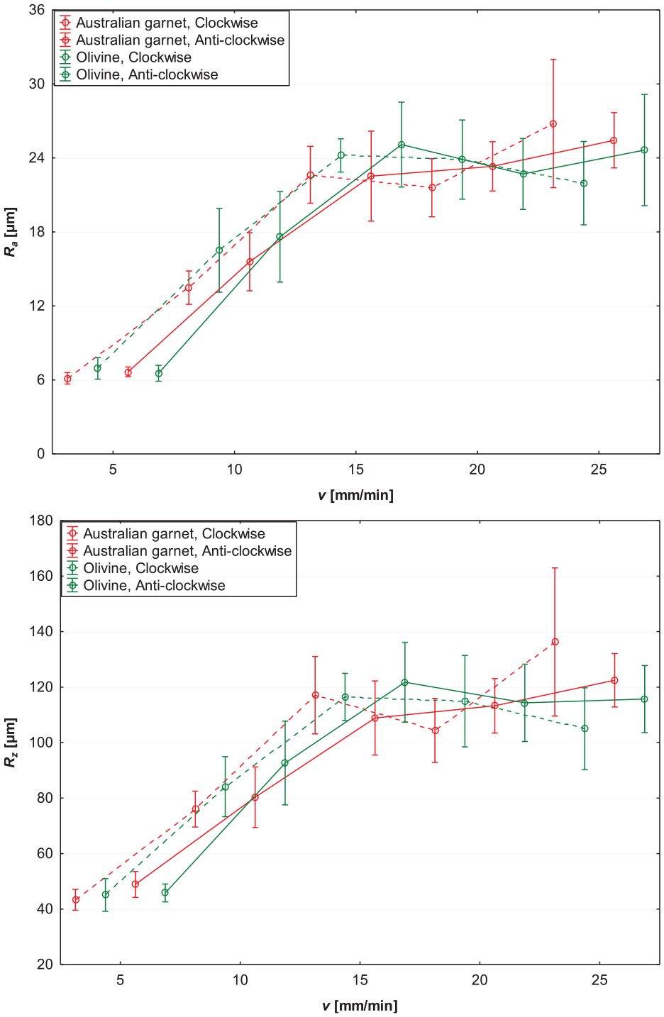
Surface roughness Ra and Rz with variation of the technological parameters.
Analysis of variance
The F-statistic has been calculated to identify those technological parameters (v, type of abrasive, and direction of rotation) that significantly (p < 0.05) affect the responses (ΔD%, MRR and Ra). Table 6 shows ANOVA results for ΔD%, MRR and Ra.
ANOVA results for (a) ΔD%, (b) MRR and (c) Ra.
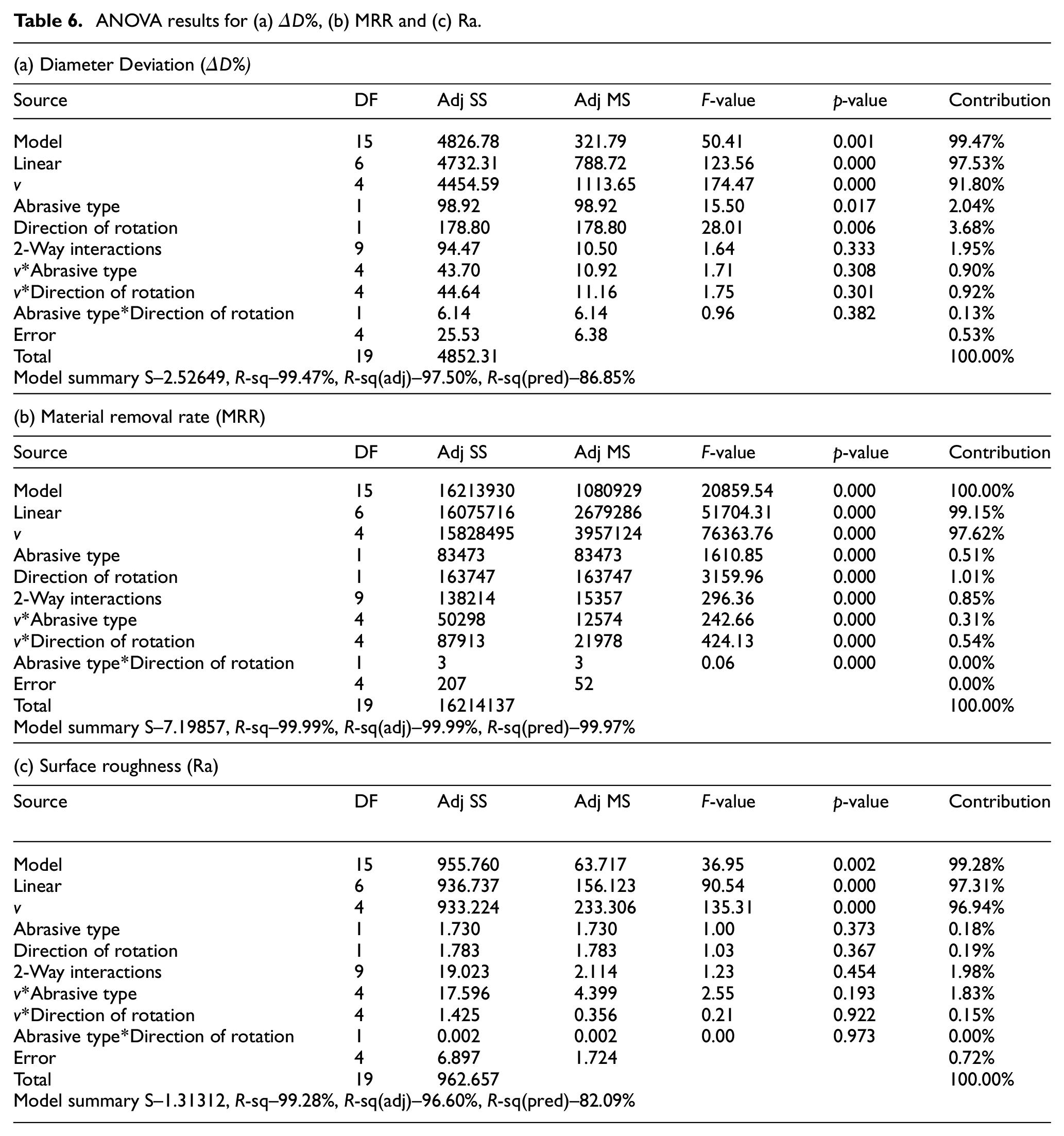
ANOVA results show that a variation in the traverse speed shows a statistically significant difference among the measured data (p = 0.000) for ΔD%, followed by the direction of rotation (p = 0.006) and the type of abrasive (p = 0.017). A two-way interactions model between the parameters shows statistically insignificant differences between the measured data (p = 0.333).
The change in ΔD% when each input parameter is varied one at a time, keeping the others constant, is shown in the main effect plot (Figure 8). The graph is plotted using the means of the responses for each factor level. 35 A linear trend of ΔD% with v, abrasive type and rotation direction is observed.
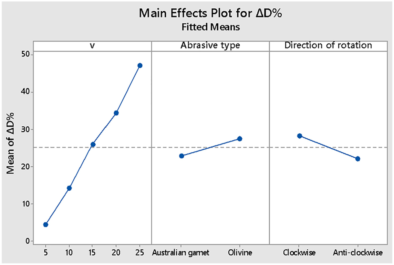
Main effect plot of ΔD% with traverse speed (v), abrasive type and rotation direction.
The ANOVA results for MRR showed with the F-statistics values that a linear model can predict the output responses (p = 0.000) with 99.15% contribution to the final model. All the three input parameters, v, the abrasive type and the rotation direction, were found to be statistically significant in affecting the output response (p = 0.000).
The main effect plot for MRR with all technological input parameters is shown in Figure 9. It also verifies the ANOVA results showing the effect of v on the MRR is statistically significant, followed by the effects of the rotation direction and abrasive type. It also shows that the optimal MRR would be with v = 25 mm/min using Australian garnet in the anti-clockwise rotation direction (3936.17 mm3/min).
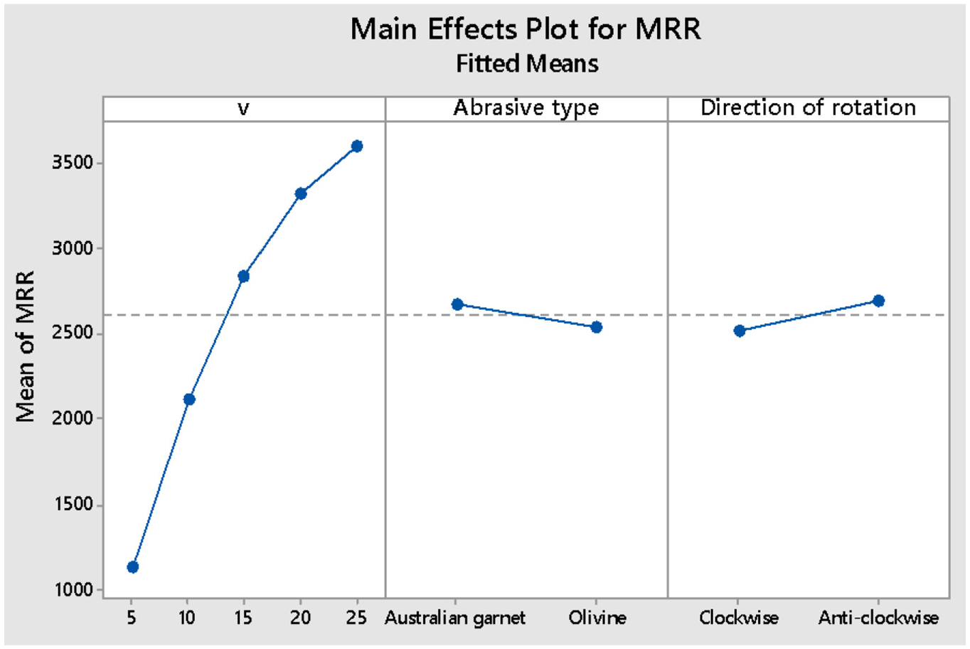
Main effect plot of MRR with traverse speed (v), abrasive type and rotation direction.
An ANOVA of Ra revealed that the linear model was statistically significant in predicting the outcome of the variations in the input parameters. The parameter v (p = 0.000) was found to be the only parameter that is statistically significant in affecting Ra. The abrasive type (p = 0.373) and rotation direction (p = 0.367) were found to be statistically insignificant in affecting Ra.
The main effect plot for Ra is shown in Figure 10. The plot shows significant variation in Ra values with changes in v but negligible variations with abrasive type and rotation direction.
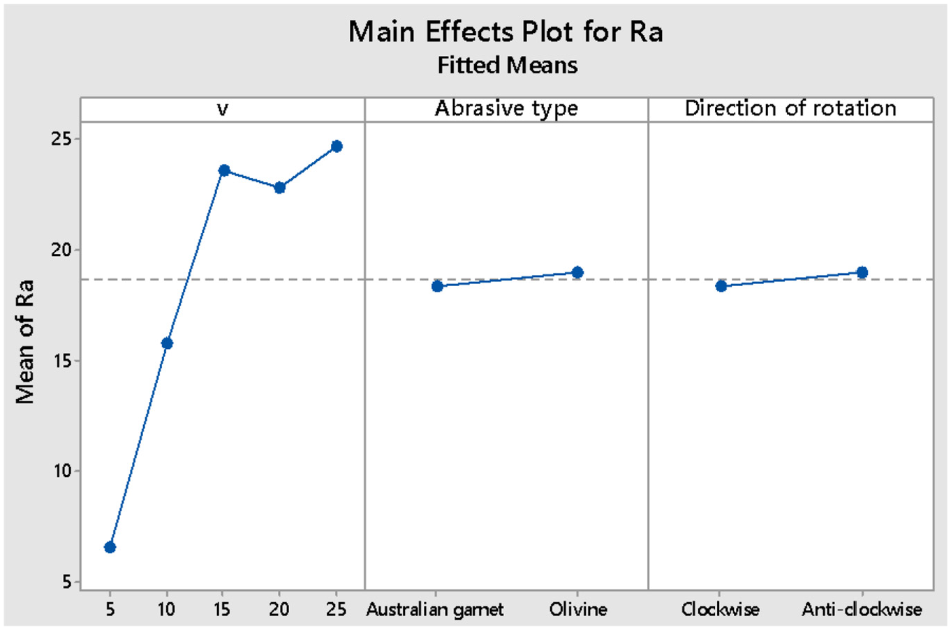
Main effect plot of Ra with traverse speed (v), abrasive type and rotation direction.
Surface morphology
The machined surface was examined by SEM to observe the surface morphology and obtain information about its characteristics and surface erosion features. SEM allows high-resolution analysis of the surface structure at higher magnification (500X). Figure 11 shows, at different magnifications, the residues of the abrasive grains that remained attached to the material surface during the sample disintegration. This image was captured from a sample section generated at v = 5 mm/min with olivine grains and a clockwise rotation direction. The average size of the abrasive grain was measured to be 34.92 µm (Figure 11(d)).
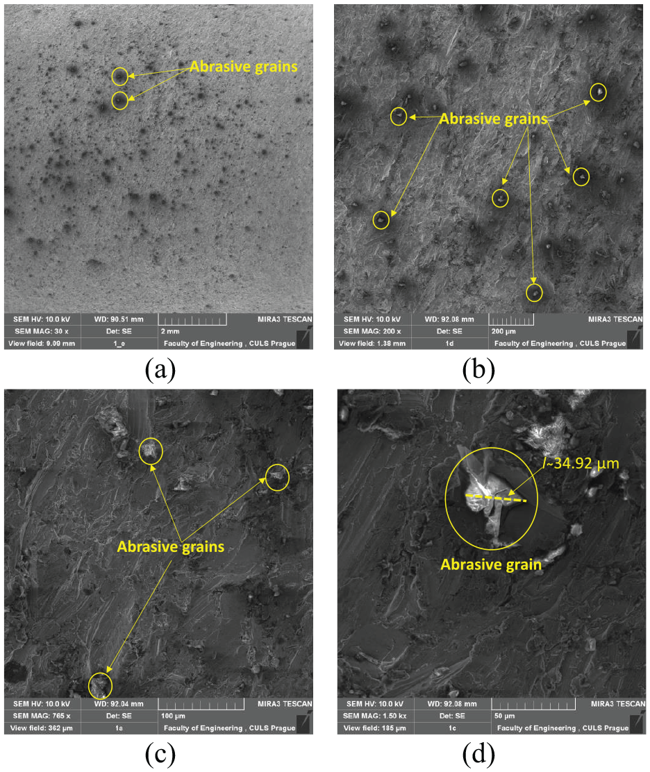
SEM image of sample section created at v = 5 mm/min, with a clockwise direction, olivine abrasive and at magnifications: (a) 30x, (b) 200x, (c) 765x, and (d) 1500x.
Figure 12 provide a magnified view of the resulting surface structure of the samples formed using Australian garnet. The comparison concentrates on samples made with the same turning parameters (i.e., feed rate) but with different rotation directions, clockwise or anti-clockwise.
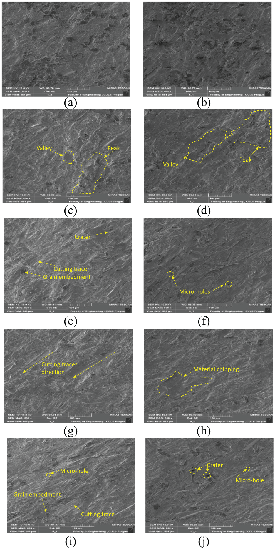
Detailed images of the surface formed using clockwise rotations at: (a) v=5, (c)10, (e) 15, (g) 20 and (i) 25 mm/min and anticlockwise rotations at (b) v=5, (d) 10, (f) 15, (h) 20 and (j) 25 mm/min with Australian garnet.
Figure 12(a) and (b) show magnified images of the sample surfaces generated at v = 5 mm/min with clockwise and anti-clockwise direction, respectively. Detailed waveforms of the peaks and valleys on the rippled surfaces can be seen. They are responsible for the differences in roughness, which can be detected at certain values of the technological parameters. The average roughness value (Ra) for clockwise rotation at a 5 mm/min traverse speed was 6.13 ± 0.46 µm, and for the anti-clockwise rotation, it was 6.65 ± 0.39 µm (Figure 12). Therefore, the undulations in the examined sample surface were insignificant and had a lower value of the mean roughness (Ra = 6.13 ± 0.46 µm).
Figure 12(c) and (d) show the surfaces created at v = 10 mm/min with clockwise and anti-clockwise rotation, respectively. An increasing feed rate resulted in deterioration of the resulting surface structure. When viewed under magnification, the surface irregularities that affect the surface roughness of the samples are identifiable. The terms ‘peak’ and ‘valley’ represent the maximum and minimum surface ruggedness present on the sample surface. The abrasive grains chip off material from the surface in irregular patterns, forming craters known as valleys, while the neighbouring area that is less eroded is referred to as peaks.
Figure 12(e) and (f) shows the surface created at v = 15 mm/min with clockwise and anti-clockwise rotation, respectively. Noticeable differences between the clockwise and anti-clockwise rotation samples at v = 15 mm/min are not clearly seen due to similar surface roughness values (Ra = 22.63 ± 2.31 µm and 22.52 ± 3.61 µm for clockwise and anti-clockwise rotation, respectively). Oblique cutting traces with abrasive grain embedment are observed in the image (Figure 12(e)). Grain embedment (Figure 12(e)) on a rotating Ti6Al4V workpiece was also observed by Kartal during disintegration by AWJ. 34 The local shear force induced in the material by the jet, exceeding the ultimate strength of the material (1020 MPa), results in forming a crater (Figure 12(e)) and micro-holes (Figure 12(f)).
Figure 12(g) and (h) show surfaces generated at v = 20 mm/min with clockwise and anti-clockwise direction of rotation, respectively. The surface roughness of the samples (21.59 ± 2.36 µm and 23.32 ± 1.99 µm for clockwise and anti-clockwise direction of rotation, respectively) differ according to the workpiece rotation direction. Additionally, the resultant cutting traces (due to the perpendicular direction of the nozzle movement and jet flow) are clearly visible in the images, which are mostly oriented 45o to the direction of nozzle movement. Hloch et.al. observed similarly inclined cutting traces on the surface of Ti6Al4V (Figure 12(g)) while hydroabrasively disintegrating rotating workpieces. 5 A valley formed due to the coalescence of craters and a hole leading to complete chipping off of the material is observed in Figure 12(h).
The highest surface roughness (Ra = 26.79 ± 5.20 µm and 25.43 ± 2.24 µm for clockwise and anti-clockwise direction of rotation, respectively) can be observed in the case of a 25 mm/min feed rate (Figure 12(i) and (j)). The surface images capture a significant irregularity in cutting traces, formation of craters, holes, and grain embedment in the surface structure, resulting in a high mean roughness (Ra = 26.79 ± 5.20 µm). This can be attributed to the shorter interaction time (2.4 s/mm) for the jet to erode the surface.
Conclusions
Experiments were carried out to measure the final diameter Df of the workpiece, the material removal rate (MRR), the mean surface roughness Ra, and the surface morphology of the disintegrated material as a response to variation in the traverse speed v, abrasive type and workpiece rotation direction. The major findings and conclusions are listed in the following.
Increasing the feed velocity from v = 5 to 25 mm/min decreases the disintegration capability, increasing the final diameter of the section (Df = 10.28 and 14.12 mm for v = 5 and 25 mm/min using Australian garnet with anti-clockwise rotation).
Using Australian garnet as the abrasive with anti-clockwise rotation results in a decrease in Df. This is due to the shape of the abrasive grains and the interaction of the abrasive jet with the material surface (Df = 15.29 mm using olivine in the clockwise direction and 14.12 mm with Australian garnet in the anti-clockwise direction, at v = 25 mm/min).
The MRR increases with an increase in v from 5 to 25 mm/min while using Australian garnet grains with anti-clockwise workpiece rotation. This increase in MRR is due to material removal from the same section with the lesser time available (MRR of 1126.99 mm2/min for v = 5 mm/min using olivine grains in clockwise workpiece rotation and 3936.17 mm3/min for v = 25 mm/min using Australian garnet in anti-clockwise workpiece rotation).
ANOVA F-tests revealed that v is the most statistically significant factor, followed by the rotation direction and abrasive type for affecting the response values of ΔDf %, MRR and Ra.
An increase in feed rate from 5 mm/min to 25 mm/min, using olivine grains in the anti-clockwise direction of rotation, has a negative effect on the resulting surface roughness. (Ra = 6.13 ± 0.46 µm for v = 5 mm/min using Australian garnet with the clockwise direction of rotation and 24.64 ± 4.51 µm for v = 25 mm/min using olivine grain with the anti-clockwise direction of rotation).
Studying the surface morphology revealed features of the eroded surface such as the formation of peaks and valleys, micro-holes, craters, and material chipping. Cutting traces generated by the abrasive particles are also observed on the surface with abrasive grain embedment in the surface.
The future direction of such research should also be aimed at examining other parameters, such as the workpiece rotational speed with simultaneous changes in the rotation direction. It is this parameter that could be the subject of further studies, to clearly determine possible differences in the results.
Footnotes
Appendix
Declaration of conflicting interests
The author(s) declared no potential conflicts of interest with respect to the research, authorship, and/or publication of this article.
Funding
The author(s) disclosed receipt of the following financial support for the research, authorship, and/or publication of this article: The experiments were conducted with the support of the Institute of Clean Technologies for Mining and Utilization of Raw Materials for Energy Use - Sustainability Program, reg. no. LO1406, financed by the Ministry of Education, Youth and Sports of the Czech Republic, and with support for the long-term conceptual development of the research institution RVO: 68145535. This study was supported by the Slovak Research and Development Agency under Contract Nos. APVV-17-0490 and VEGA 1/0096/18. The study was also supported by the project ‘Science Without Borders’, head of the project: VŠB - Technical University of Ostrava OP Research, Development and Education, reg. no. CZ.02.269/0.0/0.0/16_027/0008463.