
Abstract
The high demand of efficient large-scale machining operations by concurrently decreasing operating time and costs has led to an increasing usage of mobile robotic systems. This paper introduces a mobile robotic system which is consisted of a hybrid robot named TriMule on an automated guided vehicle, and a fringe-projection-based measurement system. TriMule exhibits desirable performance in terms of rigidity, accuracy, work envelop and reconfigurability. It is therefore suitable to be built on an autonomous platform for multi-station manufacturing in situ. In order to increase the absolute accuracy of the mobile robotic system, the fringe-projection-based measurement system obtains high accuracy and high density cloud to measure the position and orientation of the robot and workpiece in relation to each other. This system is suitable for large-scale manufacturing in situ, drilling, riveting and high-speed milling for example.
Keywords
Introduction
Large-volume manufacturing companies, for example, aeronautics, astronautics and shipping, are looking for cost-effective flexible solutions to meet the ever-increasing customer demands toward high speed and high quality.1,2 Large-scale components such as aircraft skin, space capsule are the kernel of large airplanes, aerospace equipment. Usually, this kind of component has the characteristics of large size, high length/thickness ratio, complex profile, etc., and the requirements of the dimensional accuracy and surface quality of finished workpiece are very high. For example, Airbus A220-300 aircraft has a length of 38 m and a wingspan of 35.1 m. At the same time, the number of rivets/bolt fasteners involved in the skin-assembly is as high as millions. It requires the assembly position and orientation errors are less than ±0.1 mm and ±0.5°, respectively. The strict requirements of the machining quality arise great challenges to the manufacturing equipment and process of large-scale components.
Compared with CNC machine tools, one of the important development trends in the field of large-scale machining operations in suit is the use of a mobile robotic system. 3 The idea is to install the robot or workpiece on a single- or omni-directional mobile platform to move the platform to the area where the robot can complete various processing work. In the A380 wing flexible manufacturing system at the Spain Airbus plant, fast movements over a 70 m length are achieved by mounting two sets of face-to-face Tricept 9000 hybrid robot modules on a linear guide. 4 By cooperating with a dedicated end-effector and a measurement control system, high efficiency and high precision drilling and riveting can be complete on the left and right wing panels. KUKA has developed an omni-directional mobile robot system (Omnimove mobile platform + Quantec shelf-mounted robot) for machining large turbine blades. 5 The Southwest research institute of the United States develops the MR ROAM 2 system for commercial (military) aircraft spraying. The system consists of a Motoman industrial robot on an omnidirectional mobile platform. It can be seen that the use of mobile robotic system is an effective way to achieve precise processing and assembling distributed in multiple areas of large-scale structural parts.
Instead of traditional and most frequent solution to machining large-scale parts with serial robots, a five-degree-of-freedom (5-DOF) hybrid robot (which is made up of a 3-DOF parallel manipulator and a 2-DOF serial manipulator) shows a huge potential to meet high precision requirements. 6 Some types of hybrid robots have been proposed over the last decade. Invented by Karl-Erik NeuMann, the Tricept robot7,8 is the most popular hybrid robot, and over 300 have been put into production in Boeing, EADS and Bombardier. Another hybrid robot is Exechon9,10 also invented by NeuMann. Aiming at manufacturing process of sophisticated and individualized large components, a novel 5-DOF hybrid robot named TriMule 11 was designed in our previous work. As a plug-and-play module, TriMule can be applied in the large-scale machining systems for local processing and be fixed on a mobile platform for multi-station machining.
To realize the high precision machining for large-scale structural parts, the robotic system requires not only high precision of the robots, but also corresponding measurement systems which can measure and control the precision of the robot in time.12,13 Various measurement schemes have been proposed for improving the robotic manufacturing accuracy.14–17 In general, these measurement schemes are mainly divided into two types, the first one improves the absolute positioning accuracy of the robot through measuring devices outside the robot, and the second one measures and compensates errors through the measuring devices that are mounted on the end-effector of robot. The first type usually uses external measuring devices to measure the pose of the target mounted on the robot. In the mobile robot processing system proposed by Fraunhofer IFAM, 18 the laser tracker was used to determine the position of the workpiece relative to the moving platform, and a stereo camera was used to capture the marks mounted on the robot effector in real time to improve the positioning accuracy of the robot. Qu 19 developed a robot-aided aircraft assembly drilling system based on tracker closed-loop feedback to improve the accuracy of the position and orientation of the robotic end tool. The second uses measuring devices on the robot effector to measure the machining datum or profile of the workpiece. Frommknecht 20 presented a multi-sensor measurement system for robotic drilling, which consists of a 2D camera system, laser distance sensors and contactless high accuracy distance measurement sensors for referencing and orthogonal alignment. Rao 21 proposed a method to realize robust, accurate, and online normal direction measurement and optimization to improve the surface smoothness after rivet installation by using a structural-light-based three-dimensional measurement. In contrast, the latter is more flexible due to the movement of the end-effector of the robot, and can consider the errors caused by deformations of the workpiece. In recent years, three-dimensional reconstruction technology has been widely used in the industrial field. Commonly used three-dimensional measurement methods include fringe projection technology, 22 binocular vision, 23 and laser radar. 24 Compared to other methods, fringe projection technology has high resolution, real-time operability and robustness. 25 The measurement system can perform on-line measurement of the workpiece profile and measure the position and orientation of the robot and workpiece in relation to each other, which makes robotic machining more flexible.
This paper introduces a mobile robotic system, which consists of a hybrid robot mounted on a mobile platform and a fringe-projection-based measurement system. The measurement system enables fast measurement of the machined surface profile and provides dense and high-precision 3D point cloud. In order to determine the positional relationship between the reference coordinate system and the robot coordinate system efficiently, a vision-based method is proposed to measure the position of the reference features. To solve the problem that the actual profile of the workpiece does not conform to the CAD model due to machining error, stress release and uneven workpiece clamping force, the system can estimate the profile error by matching and comparing the actual surface profile and the CAD model to reduce the effects of workpiece deformation. Due to the absolute positioning error of the robot, the deformation of the workpiece and other factors, the normal direction of drilled surface are required to be measured online. The system enables to measure the profile of the drilled surface and determines the normal direction at the drilled point. In this paper, the process for aligning the robotic tool to the measured surface is also studied.
The remainder of the paper is organized as follows. Section 2 describes the mobile robot processing system and focuses on the robot and the fringe-projection-based measurement system. In Section 3, some measurement tasks that the system can achieve are introduced. In Section 4, the experimental setup and results achieved are presented. Finally, conclusions are drawn in Section 5.
Descriptions of the mobile robotic system
As shown in Figure 1, the mobile robotic system mainly consists of a hybrid robot named TriMule, a fringe-projection-based measurement system, an automated guided vehicle (VGA) and a flexible fixture, etc. TriMule is mounted on the VGA that greatly extend the workspace. The measurement system is mounted on the robot’s end-effector for high-precision 3D measurement in the work area. Combined with the high-speed electric spindle and tools on the end-effector, the system can complete the high-efficiency and high-precision drilling, riveting and milling for large-scale structural parts in situ.
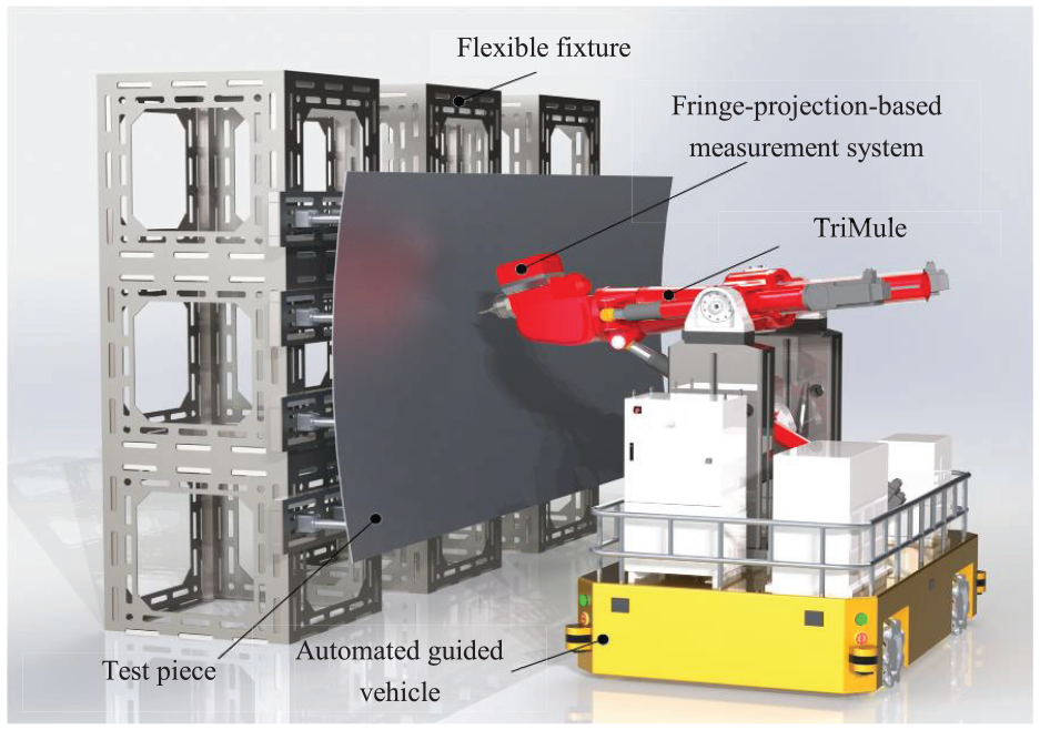
Conceptual design of the mobile robotic system.
The technical scheme of the mobile robotic system has the following advantages: (1) the system has low-cost and strong reconfigurability, which can be rapidly rearranged according to the task requirements to build a multi-robot collaborative manufacturing system; (2) the robot equipped with various end-effectors is convenient to quickly reach the optimal working position, which has stronger adaptability to the machining of large curvature surface; (3) the robot is flexible in motion and suitable for working in narrow space, and furthermore the collaboration of multi-robot can significantly improve the work efficiency; (4) the accurate metrology information allows the robot to perform tasks such as measuring the shape of an irregular surface, which would have been very difficult to automate.
TriMule
TriMule11,26 is a novel 5-DOF hybrid robot that is composed of an over-constrained 1T2R (T, translation; R, rotation) parallel mechanism and a 2-DOF wrist, as shown in Figure 2. The parallel mechanism comprises an actuated UPS limb and a stand-alone 1T1R planar linkage that contains two actuated RPR limbs and a properly constrained passive RP limb in-between. The base link of the 1T1R planar linkage is elaborately designed into a three-in-one part that locates the rear R joints of the two actuated RPR limbs, and the R and P joints of the RP limb, and at the same time it is connected by a pair of R joints with the machine frame. R, P, U, and S stand, respectively, for revolute, prismatic, universal, and spherical joints where the underlined joint represents the actuator. This feature brings a special issue that the compliance compatibility conditions amongst three planar limbs must be taken into account in the semi-analytic stiffness modeling of the parallel mechanism. In brief, TriMule is an overconstrained 1T2R parallel mechanisms can have several advantages over their counterparts that lack overconstraints: higher stiffness, greater cost-effectiveness, and easier-to-obtain explicit inverse/forward kinematics.
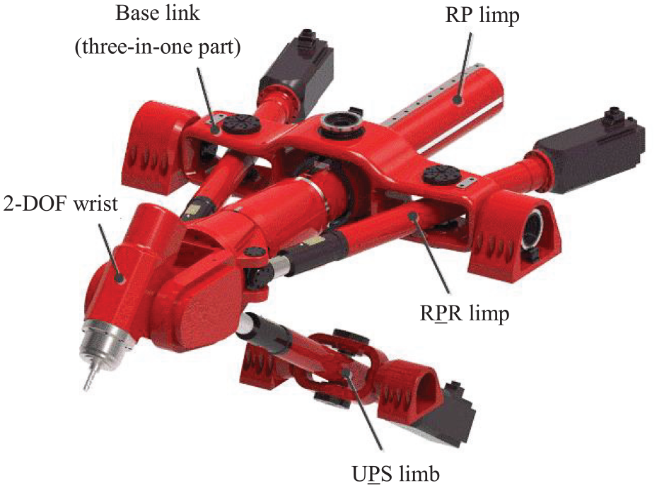
3D model of TriMule.
Fringe-projection-based measurement system
In the mobile robotic system, a fringe-projection-based measurement system is used to increase machining accuracy. The structure of a measurement system can be shown in Figure 3(a).The measurement principle is based on fringe projection profilometry.
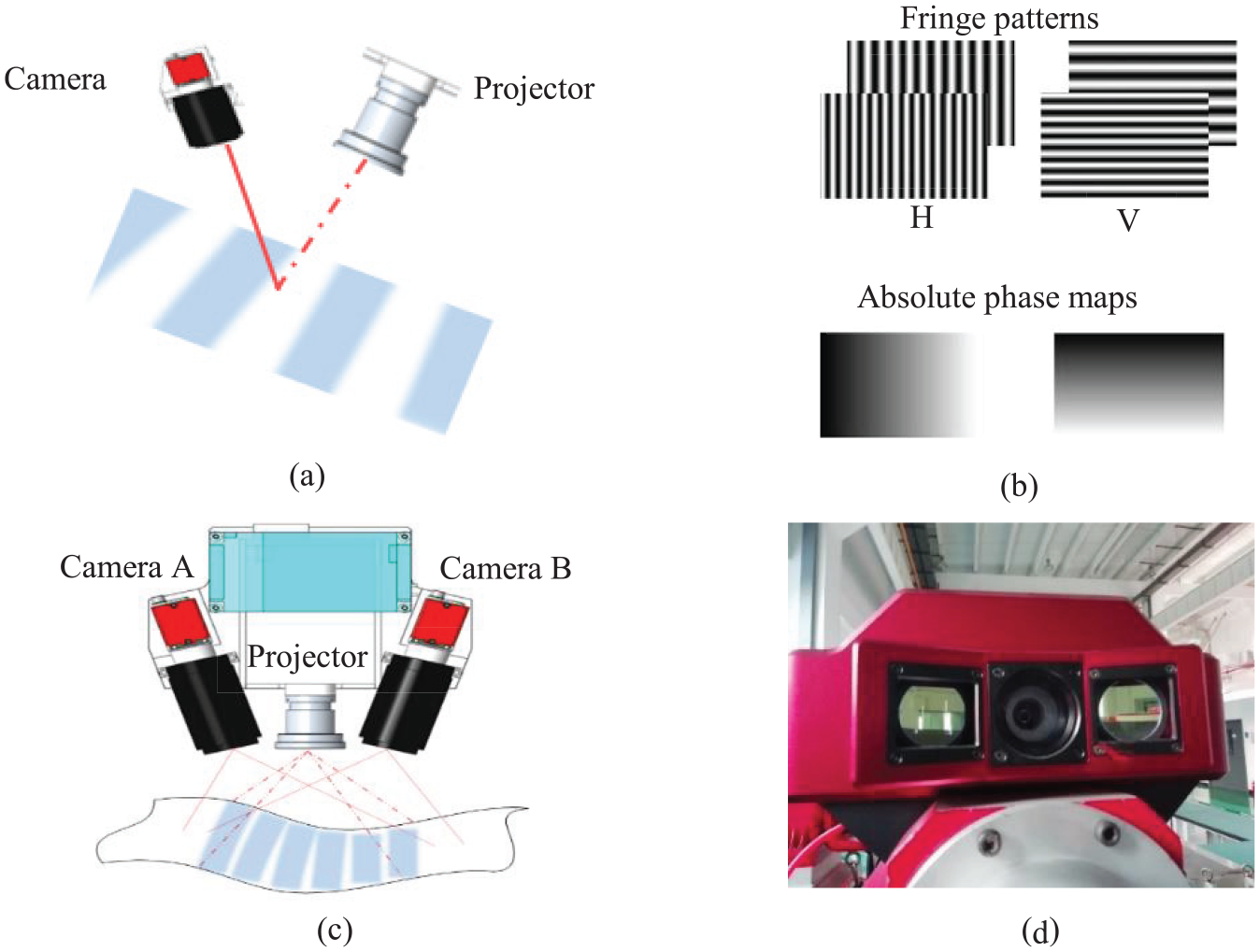
A fringe-projection-based measurement system: (a) the structure of the one projector-and-one camera, (b) fringe patterns and absolute phase maps, (c) the structure of the one projector-and-two cameras, and (d) the prototype of the three-dimensional measurement system.
First, four-step phase shifting method 27 and three-frequency unwrapped method 28 are applied to calculate the absolute phase. Twelve fringe patterns (four step phase shifting patterns on each of the three frequencies) are projected onto a standard plane and the camera captures these fringe patterns. The absolute phase map on the camera image plane can be calculated as the weighted average of the three wrapped phases.
Then, the one-to-one mapping relationship between the point on projector image plane and the corresponding point on camera image plane are established. The projector projects two sets of patterns (with horizontal and vertical fringes as shown in Figure 3(b)), the real one-to-one mapping relationship between the pixels on the projector and camera image plane can be established by searching the identical phases.
However, the optical structure of the projector in this measurement system can be regarded as a reverse of an imaging system (camera). The projector should be calibrated precisely to obtain three-dimensional point cloud accurately. Therefore, we use double cameras to avoid accurate calibration of the projector (as shown in Figure 3(c)). The phase information of the fringe image produced by the projector is only used as the basis of binocular matching, so the accuracy of the projector has little effect on the measurement system. Figure 3(d) shows the prototype of the three-dimensional measurement system.
3D measurement
Referencing
In order to determine the reference coordinate system efficiently and accurately, we propose a method based on binocular vision. The coarse position and orientation of the workpiece and robot with respect to a common reference frame is assumed to be known. When the end-effector of robot moves to the nominal coordinates, the measurement system can find the reference features. Here sticky tags are used as reference features. As shown in Figure 4(a), the reference features are circular reflective markers that provide a clear image when they are photographed by the camera. Three markers are used to define a reference coordinate system in the paper. It is noted that more markers can be used to mitigate measurement errors.
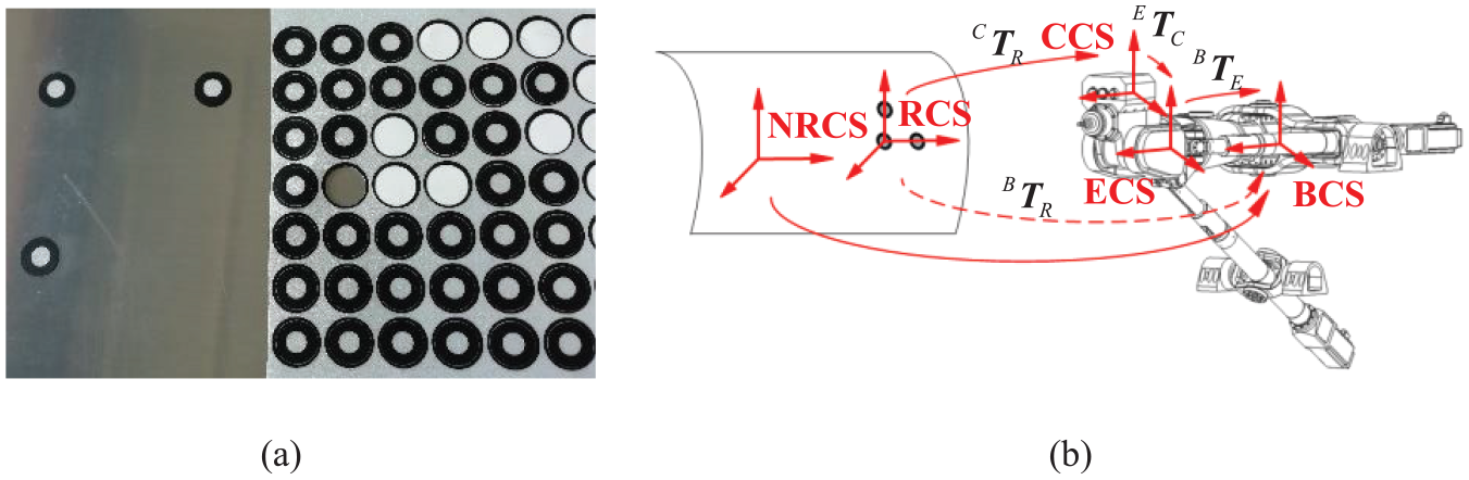
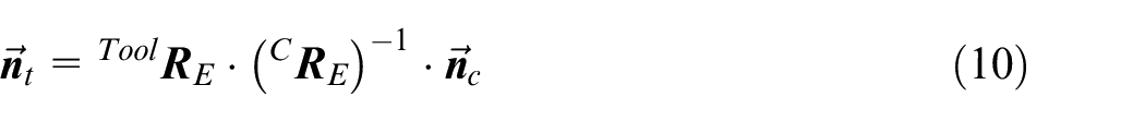
Coordinate frame of the mobile robotic system: (a) circular reflective markers and (b) machining datum measurement and coordinate transformation among frames.
To determine the position and orientation of the machining data, the mobile robotic system approaches the workpiece at its nominal reference coordinate system (

where the homogeneous matrix of camera coordinate system to robot end-effector coordinate (
In our previous work, we proposed an algorithm for estimating the pose of circular marker. 29 The method uses the circular contour obtained by the monocular camera to estimate the pose information of the spatial circle whose radius is known. Firstly, the circular marker has been mapped to be an upright elliptic cone in the pinhole imaging model. Secondly, radius constraint has been applied to recover depth of the circular marker based on the upright elliptic cone. Finally, the pose of the circular marker has been estimated by single projection only.
Profile error estimation
For a large-scale structure part, the actual profile is likely to be different from that in the CAD model due to the tool error, cutting force, and deflection due to assembly stress. Hence, a method of online measurement and model matching is proposed to compensate error. The profile of the workpiece is measured online, and the actual profile is aligned with the ideal model. Then, the deviation of the actual workpiece profile and the CAD model is calculated.
The mobile robotic system can control the three-dimensional measurement system to measure the area to be processed. The point cloud

where translation vector

Since both the robot and the measurement system have been calibrated, the point cloud
where

The mean square objective function to be minimized can be defined as
where
Implementation of auto-normalization
Robotic drilling for large-scale parts demands high positioning accuracy of robots, which is usually achieved through error measurement and compensation online. In order to measure the normal direction of drilled surface efficiently and accurately, a method based on point cloud is introduced.
Normal direction measurement
At the beginning of the robotic drilling process, the robot moves to drilled point according to the NC program written by off-line programming system. As shown in Figure 5, the point cloud of the workpiece surface is acquired by the proposed the fringe-projection-based measurement system. It is well established in differential geometry that the local geometric shape of a point can be approximated by a quadric surface. So, in order to extract the normal direction at the target drilling position
where A∼K are the coefficients of quadratic surface. To solve the coefficients, an objective function of fitting quadric surface is established
where N is the number of neighborhood points,
Then the normal vector
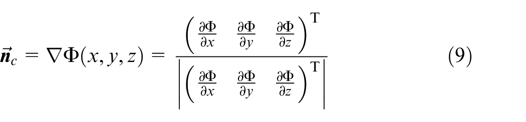
The normal direction
where
Measurement chain.
Alignment method
As shown in Figure 6, the unadjusted tool coordinate system is named
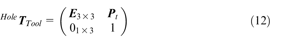
where
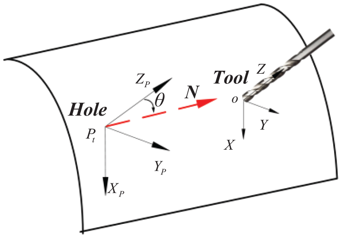
Geometric model.
Supposing the outer normal vector to the drilling skin surface is shown as
As shown in Figure 7,
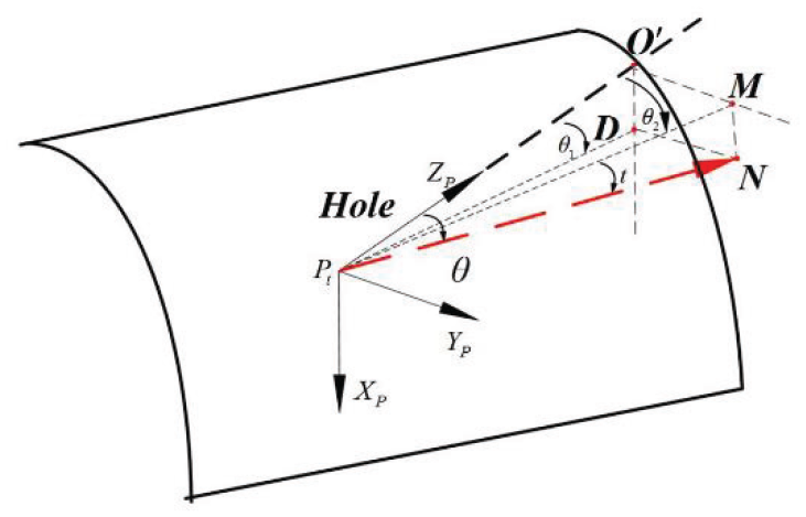
Relationship between
Assuming

It is known that
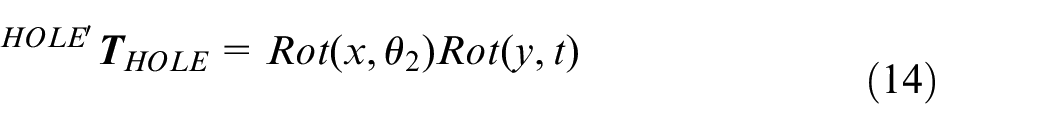
The homogeneous matrix of the robot base coordinate system with respect to

The homogeneous matrix of the robot base coordinate system with respect to

After the robot compensates for the error, the adjusted tool should be above the target drilled point, and the tool direction is consistent with the normal direction of drilled surface. So the relationship between the adjusted tool coordinate system
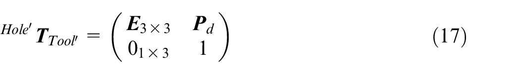
where
Thus, the target configuration of tool can be calculated as
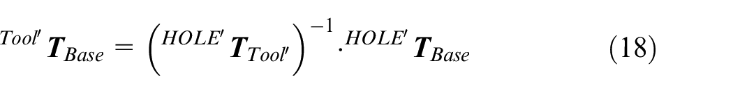
The procedure of the method is shown in Figure 8.
Workflow of robotic drilling process.
Experiments and discussions
Measurement accuracy of the measurement system
Error of the measurement system will affect error compensation in robot machining, so the precision of measurement system is very important in this study. In the experiment, a standard part consisting of two standard balls has been used. As shown in Figure 9(a), the standard ball was bonded to a flat plate and the relative position of the standard ball is fixed.
Accuracy verification of the measurement system: (a) standard part measurement and (b) point cloud of standard part.
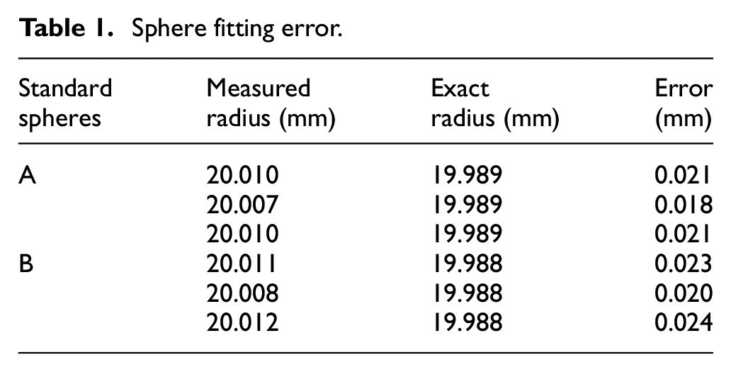
The standard part was measured by fringe-projection-based measurement system. Then the point cloud data was used to fit two standard spheres A, B as shown in Figure 9(b). Supposing that the spherical coordinates of the fitted balls are
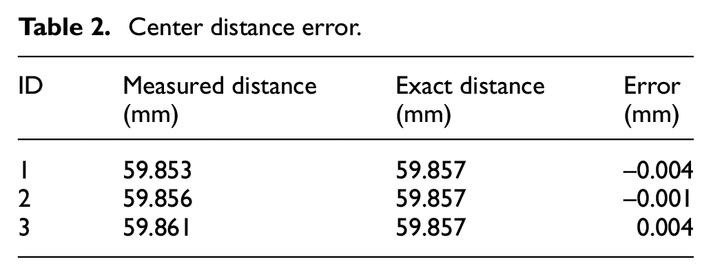
In order to evaluate its measurement accuracy, the exact radius and distance were measured with a CMM (coordinate measuring machine). The maximal deviation of radius was 0.024 mm (see Table 1), and the maximum distance error was 0.004 mm (see Table 2), which demonstrates that the measuring accuracy of the measurement system is good enough.
Sphere fitting error.
Center distance error.
Measurement accuracy of the robotic system
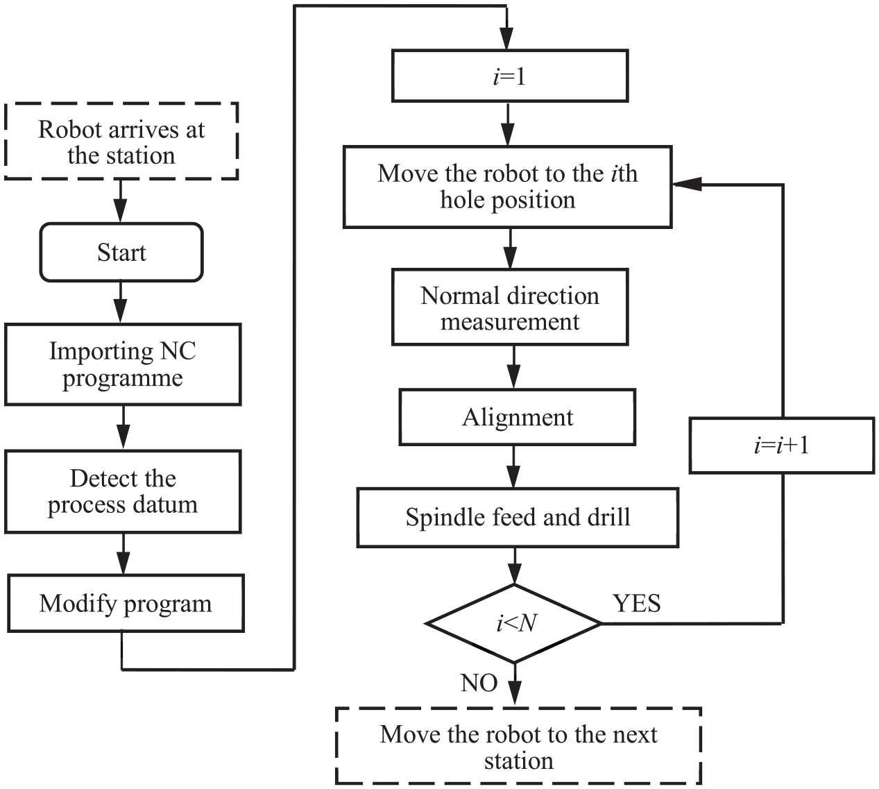
In order to verify the accessible measurement accuracy in the course of processing, one measurement scheme was established as shown in Figure 10. The fringe-projection-based measurement system was mounted on TriMule’s end-effector and a test workpiece with reference features was fixed on the fixture.
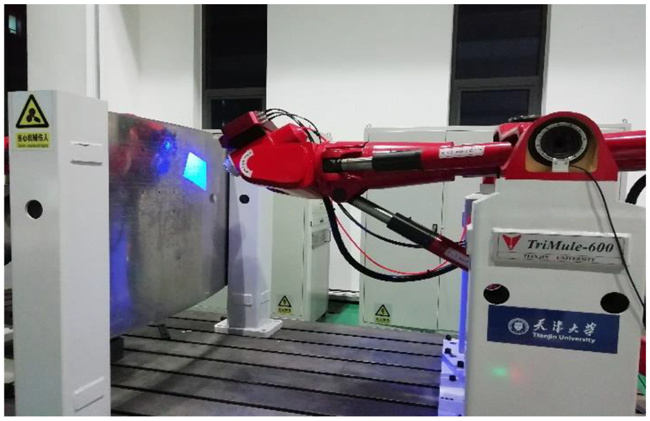
Experiment setup.
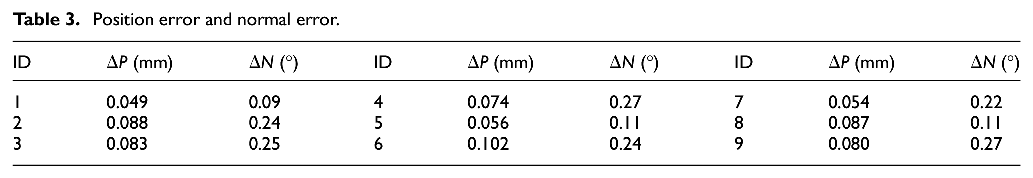
In the experiment, some benchmarks were placed near the reference features. The exact positions of reference features and benchmarks were measured with a CMM, transformed to reference coordinate system. In order to compute the exact normal directions of the benchmarks, the surface patches around the benchmarks were also measured with a CMM. Then the reference features were measured by the fringe-projection-based measurement system to establish the reference coordinate system, and the robot was programmed to approach each benchmark to measure the position and normal direction of each benchmark and transfer them to the reference coordinate system. The position of benchmarks was obtained via triangulation using the calibrated parameters of the two cameras, and the normal direction of the benchmarks was computed through the method described in Section 3.
Table 3 shows the position error
Position error and normal error.
Conclusion
In this paper a mobile robotic system for large-scale manufacturing has been introduced. The system is able to measure the workpiece profile online and obtain dense point cloud with high precision by the fringe-projection-based measurement system. The measurement system enables the robot to measure the pose of the reference feature and establish the reference coordinate system efficiently. 3D point cloud of actual surface profile is matched with CAD model to estimate the profile error, which can reduce the effect of workpiece deformation. Furthermore, a method of normal direction measurement based on 3D point cloud is proposed to reduce the normal error during drilling, and the process for aligning the robotic tool to the measured surface is theoretically analyzed. The proposed methods are verified by experiments. It can be concluded from the results that the integration of fringe-projection-based measurement system on a mobile robotic system offers a fully automated and high efficiently alternative solution for large-scale manufacturing. It is worth pointing out that one-station measurement and machining is studied in this paper. Multi-station measurement and machining will be analyzed soon and more experiments will be conducted to validate effectiveness of the mobile robotic system.
Due to large-scale of complex components, it brings great challenges to the measurement of component size and the evaluation of machining quality. Furthermore, it seriously affects the selection of machining allowance, trajectory planning and control parameters of the robot, so it is necessary to establish a flexible and precise measurement mechanism based on the multi-sensor information fusion, which can not only realize in-situ precise measurement and machining quality assessment oriented to multi object and multi process, but also provide powerful data support for autonomous decision-making and adjustment of robot machining process and meet the needs of robot autonomous machining.
Footnotes
Declaration of conflicting interests
The author(s) declared no potential conflicts of interest with respect to the research, authorship, and/or publication of this article.
Funding
The author(s) disclosed receipt of the following financial support for the research, authorship, and/or publication of this article: This work was supported by the National Key Research and Development Program (Grant No. 2017YFE0111300), National Natural Science Foundation of China (Grant No. 51775376), and EU H2020 project (Grant No. 734272).