
Abstract
Compared to the traditional cropping technology, low-cycle fatigue cropping can reduce load and improve cross-section quality. Geometric factors of V-shaped notch and processing parameters (such as load amplitude and load frequency) influence the cropping efficiency and section quality. By changing the factors, the sufficient efficiency of cropping and quality of cross-section get together. However, the influences of material defects, geometric parameters, loading frequency and other factors are different in each stage of the whole cropping process. If the effects of the parameters on the each stage of cropping process are clear, the higher productivity and the better cross-section quality will be obtained by applying suitable parameter on each stage of cropping process. To investigate the effects of eccentric ratio on each stage of low –cycle fatigue cropping process, a suitable monitoring method is needed. This study proposes acoustic emission (AE) technique to detect the low-cycle fatigue cropping process of 16 Mn eccentric bar (The bar prefabricated eccentric notches. The prefabricated notch improve the efficiency of cropping). The parameters of signals such as counts and kurtosis during the low–cycle fatigue process are obtained. According to the counts changes over time, the process of the 16 Mn metal bar cropping can be divided into three stages: the crack initiation stage, the crack propagation stage, and the fracture stage. Based on the cumulative counts, the eccentric ratio’s influence on the time of each cropping process stage is obtained. The time of the crack initiation stage and the final fracture stage doesn’t increase with the eccentric ratio. The time of the propagation stage influenced by the eccentric ratio greatly. Besides, the eccentric ratio’s influence on the cross-section quality is studied by using an advanced optical microscope system. The cross-section quality was influenced by the eccentric ratio significantly. The results of the paper indicate the acoustic emission (AE) monitoring technique is a useful method to detect the process of low-cycle fatigue cropping. Especially, it provide effective information to investigate the effects of the notch eccentric ratio during the low-cycle fatigue cropping process. The eccentric ratio’s effects on each stage of low-cycle fatigue cropping process offer guidance to improve low-stress fatigue cropping efficiency and cross-section quality.
Keywords
Introduction
The cropping technology for metal bars and tubes has been widely used in numerous industrial applications including automobile, aerospace, and bearing. Disadvantages in traditional cropping technology such as high load, low efficiency, and poor section quality lead to imperfect application results. To solve the above-mentioned problems, the low-cycle fatigue cropping (LCFC) was introduced. LCFC utilizes the stress concentration on the prefabricated V-shaped notch of the metal bars or tubes. Due to the stress concentration effect, cracks initiate at the root of the notch. Under the cyclic bending load, the cracks propagate along with the V-shaped notch until fracture.1–4
To improve the cropping efficiency and the section quality, much attention has been devoted to the factors which have a strong influence on the LCFC. Many authors1,5–7 investigated the influence of the V-shaped notch. Zhao 1 found that the mean stress of the metal bar in the cropping process can be effectively reduced due to the stress concentration effect of the V-shaped notch. Zhang 5 showed that the stress of the bar in the vertical direction is greater than that in the horizontal direction, which proves the cropping method is feasible. Zhong et al. 6 had studied the notch-sensitivity. Based on these studies, we conclude that the ductile damage initiation criterion is influenced evidently by the clearance and the notch-sensitivity. Other researches have been conducted regarding the influence of the load frequency. Zhao et al. 8 pointed out that the metal bar’s stable crack propagation and fracture are obtained when constantly increasing the striking displacement and reducing the striking frequency in the cropping process, simultaneously. Tang et al.9,10, Zhong et al. 11 and Zhang et al. 1 found that a linear increment of the stroke-time curve and a linear decrement of the strike frequency-time curve improve the cropping efficiency and the quality of the fracture section. By changing the above factors, the sufficient efficiency of cropping and qualified quality of cross-section get together. However, the influences of material defects, geometric parameters, loading frequency and other factors were different in each stage of the LCFC process. 12 . If the effects of the parameters on the each stage of cropping process are clear, the higher productivity and the better cross-section quality will be obtained by applying suitable parameter on each stage of cropping process. To investigate the effects of eccentric ratio on each stage of low –cycle fatigue cropping process, a suitable monitoring method is needed.
Acoustic Emission (AE) is one useful technique to monitor deformation, fracture and natural damage.13–16 It can be used to investigate the effects of the parameters on each stage of the LCFC process. AE is defined as a phenomenon whereby elastic waves are generated by the rapid release of energy from a source within a material. The sources of AE during the process of cropping include plastic deformation, crack initiation and crack growth. 17 AE signals contain information about the microstructure change during the cropping process. Some interesting results about parameters of the AE signal have been reported. Han et al.18,19 and Li et al. 20 investigated the evolution of counts accumulated and divided the whole process into three stages. The first stage was related to crack initiation, the second stage was related to stable crack growth and the third stage was related to the rapid crack growth and the final fracture. Lin et al. 21 applied Hilbert-Huang transform (HHT) signal processing technique on AE feature extraction of natural fatigue cracks in rotating shafts providing a time-frequency-energy distribution. Chai et al. 22 reported a new parameter: AE entropy. By using AE entropy, he investigated the characteristics of fatigue crack growth in 316LN stainless steel. AE entropy is available for identifying the transition from plane strain to plain stress state. The AE entropy can be used for accurately assessing the fatigue damage. Roberts et al. 23 set up a relationship among AE parameters, stress intensity and crack growth behaviors which can be described as the following equations:


In the above equations,
Our project team focuses on LCFC technology. In our previous report, 12 the AE technique was applied to monitor the crack initiation, propagation and final fracture of stainless steel 304 tubes during the LCFC process. The influence of high-frequency load condition and low-frequency load condition was compared in this study. In this paper, the AE technique was used as a monitoring method to detect the LCFC process of 16 Mn eccentric metal bar (eccentric V-shaped notch improve the efficiency of cropping). The influence of the eccentric ratio during each stage of the LCFC process was investigated. The results will beneficial to LCFC process control attempting to increase the cropping efficiency and quality.
This paper was organized as follows. Section 1 presents the previous study about the LCFC method and the AE technique. Section 2 presents the structure of the cropping machine, parameters of the AE system, properties of the materials and the experimental setup. In Section 3, the results and discussions of the AE activity are presented. Finally, Section 4 summarizes the main conclusions of this paper.
Materials and methods
The objective of this experiment was to investigate the characteristics of the LCFC process and the impact of the V-shaped notch’s eccentric ratio on efficiency and cross-section quality. Experimental tests were conducted for the 16 Mn metal bar on a type of LCFC machine. The detailed description of the properties of the 16 Mn and the geometric details of the metal bar were presented in Section 2.1. Fundamental information for the new LCFC detecting system was provided. The LCFC detecting system included two parts: LCFC system and AE detecting system. The principle of the LCFC method and the composition of the LCFC machine was presented in Section 2.2. The composition of the AE detecting system and the methods of data processing were described in Section 2.3.
The properties of the 16 Mn and the geometry of the metal bar
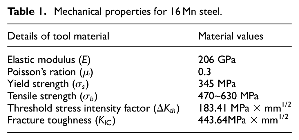
The mechanical properties of the 16 Mn are presented in Table 1. The metal bar which is caught in the clamping apparatus can be simplified as the load diagram in Figure 1. The distance between the clamping position and the tip of the V-shaped notch is 10 mm (L1). The distance between the tip of the V-shaped notch and the loading point is 70 mm (L2). The diameter of the metal bar is 20 mm (D). The bottom corner radius of the V-shaped notch is 0.1 mm(r). The radius of the notch root is 9 mm (h), the depth of the V-shaped notch was 1 mm and the flare angle of the V-shaped notch is 45o(
Mechanical properties for 16 Mn steel.
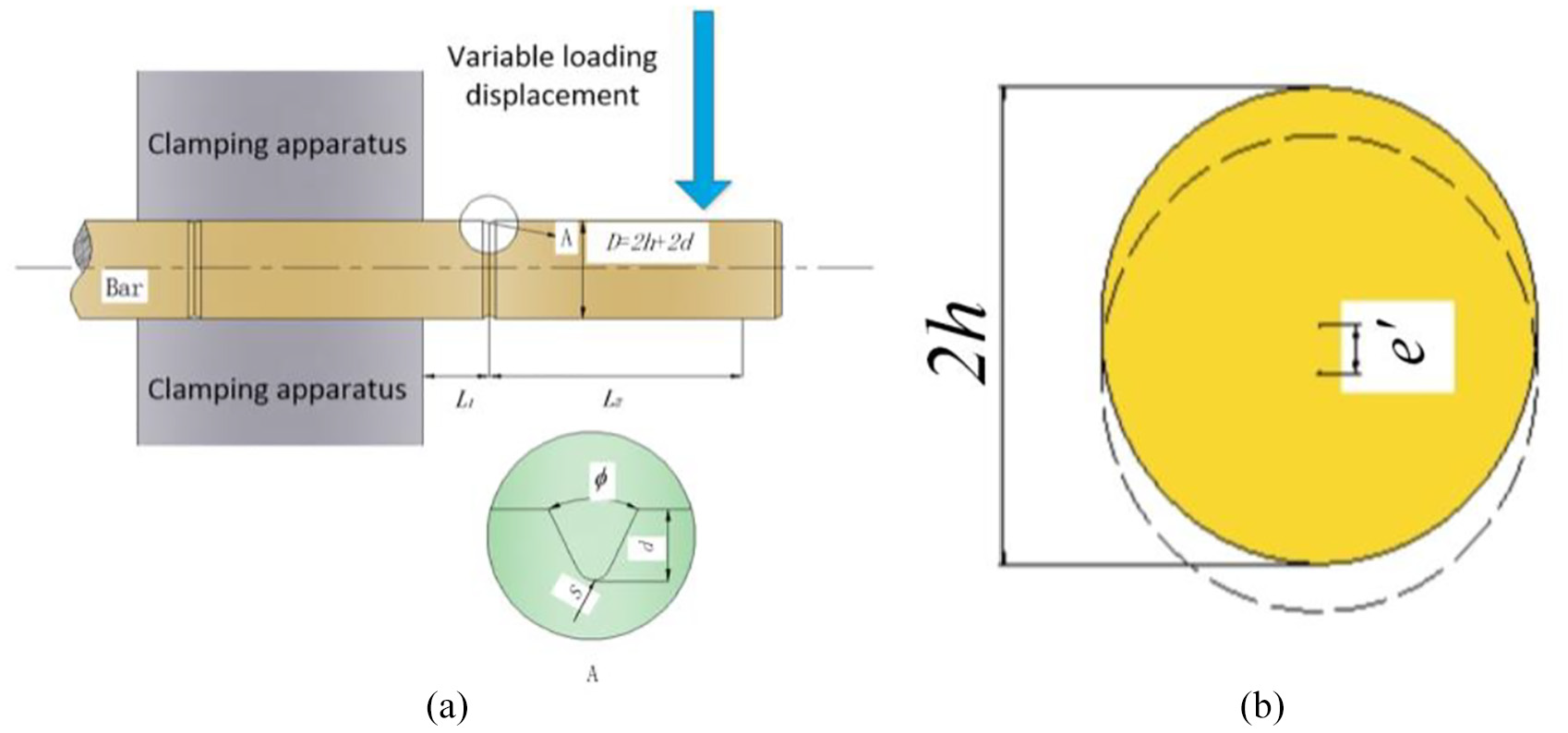
(a) Force diagram of the metal bar. The geometric details of the metal bar were presented. (b) e’ represents the notch eccentric distance. The dotted line represents the slotting notch trajectory.
The principle of the LCFC method and the composition of the machine
The principle of the LCFC method is shown in Figure 2(a). The apparatus fundamentally consisted of a clamping apparatus, a blanking die, a spindle and an eccentric die. One end of the metal bar is clamped at the position of the V-shaped notch, while the other end of the metal bar is put into the blanking die. The axis of the metal bar coincided with the axis of the blanking die
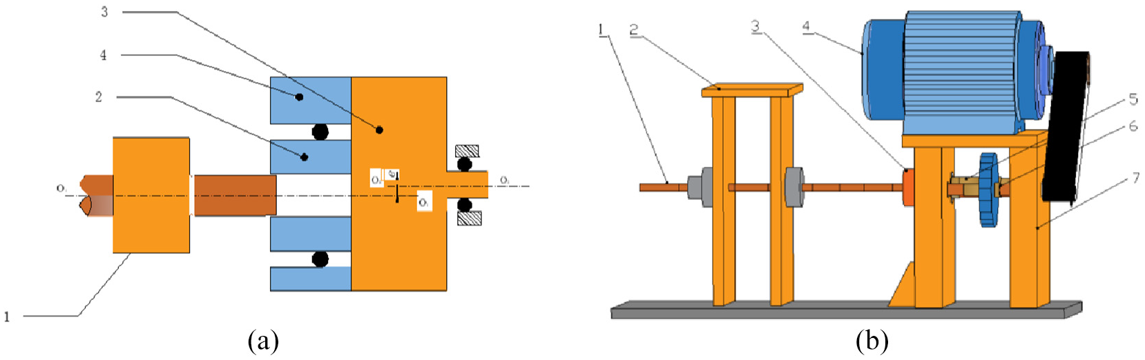
Schematic diagram of LCFC system and the composition of the LCFC machine: (a) 1. Clamping apparatus 2. Blanking die 3. Spindle 4. Eccentric die, (b) 1. Spindle 2. Clamping mechanism 3. Blanking die 4. Variable frequency motor 5. Spindle 6. Drive shaft 7. Body frame.
The cropping machine is shown in Figure 2(b). It consisted of a variable frequency motor, a blanking die, a clamping mechanism, a body frame, a drive shaft and a spindle. The blanking die’s eccentric distance was equal to 3 mm. The rotational speed of the cropping is adjusted by the inverter, which was speed controlled by a programmable logic controller (PLC). In this study, the rotational speed is set as 3000 RPM, the inverter frequency is 15 Hz and the cyclic loading frequency is 30 Hz.
AE detecting system
To monitor the process of the LCFC, the AE detecting system is established. As shown in Figure 3, the AE system is composed of an AE sensor, an external power supply, an amplifier and a high-performance data acquisition card. The AE sensor used is Nano30 by Physical Acoustics Corporation with a peak frequency of 293 kHz and a bandwidth of 125–750 kHz. The resonant of the sensor is 140 kHz. The AE sensor is mounted on the surface of the clamping mechanism by using a coupling material and a magnetic seat. The external power supply of 28V DC is used to power a variable gain 2/4/6 amplifier. The high-performance data acquisition card is Advantech PCI-1714U, which recorded the AE signals. The maximum sampling rate of the data acquisition card is able to reach 30MS/s.
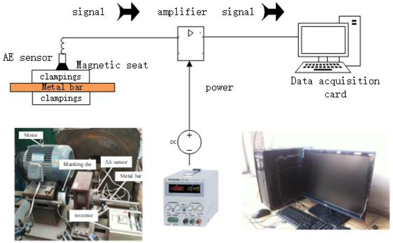
The compositions of AE system.
To get valid data, the sampling rate is set as 2 MHz. A bandpass filter within the frequency range of 25 to 800 kHz is used to preprocess the AE waveforms obtained in the cropping process. The amplitude of background noise is about 0.1V. To avoid noise signal interference to the cumulative counts, a suitable threshold value of the peak amplitude was necessary. The threshold value was set at 0.2V, about two times above the operational background noise. This setting method ensure the accuracy of the cumulative counts. The parameters of the AE signals are calculated for 200 ms, during which at least five cycles of rotation are performed.
The experiments are performed using the following procedure. First, the motor is started in 2 s, and then switches to a constant rotational speed. Then the cyclic load is applied to the metal bar. At the root of the v-shaped notch, due to the stress concentration effect, the crack initiates and generates the AE signal. The signal is in the form of voltage, which is collected in Datalogger. Then it is converted to a text file and put into Matlab. After being handed by the low pass filter, the parameters such as amplitude, cumulative count of peak events and kurtosis are finally obtained.
Results and discussions
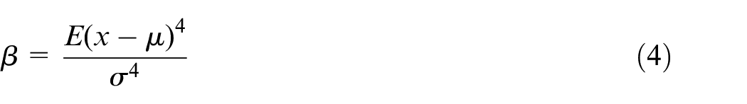
According to the previous studies,14, 22, 29,30 the counts, kurtosis and amplitude of the AE signal are used to characterize the process of LCFC commonly. Due to the amplitude is not influenced by the threshold value of the peak amplitude. Hence, the amplitude signal containing interference signals. Besides, the amplitude represents the intensity of the signal. It couldn’t characterize the frequency of plastic and fracture events. The counts characterize the initation stage and propagation stage effectively. The kurtosis is suitable to be used to characterize the fracture stage. Hence, the counts and kurtosis are selected to investigate the LCFC process.
The AE parameters such as the AE signal waveforms at some typical times, counts and kurtosis during the cropping process are shown in Figures 4, 5, and 7. The photographs of the cropping cross-section are shown in Figure14. In this part, the characteristics of the AE signal during the LCFC process are discussed in Section 3.1, the influence of the notch eccentric ratio on the duration of every phase is discussed in Section 3.2 and the influence of the notch eccentric ratio on the fracture section quality is discussed in Section 3.3.
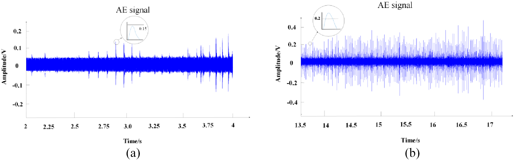
The voltage peak value of the AE signal in the typical time: (a) the voltage peak value of the AE signal from 3s to 4s when e’/D=0, (b) the voltage peak value of the AE signal from 14s to 15s when e’/D=0.
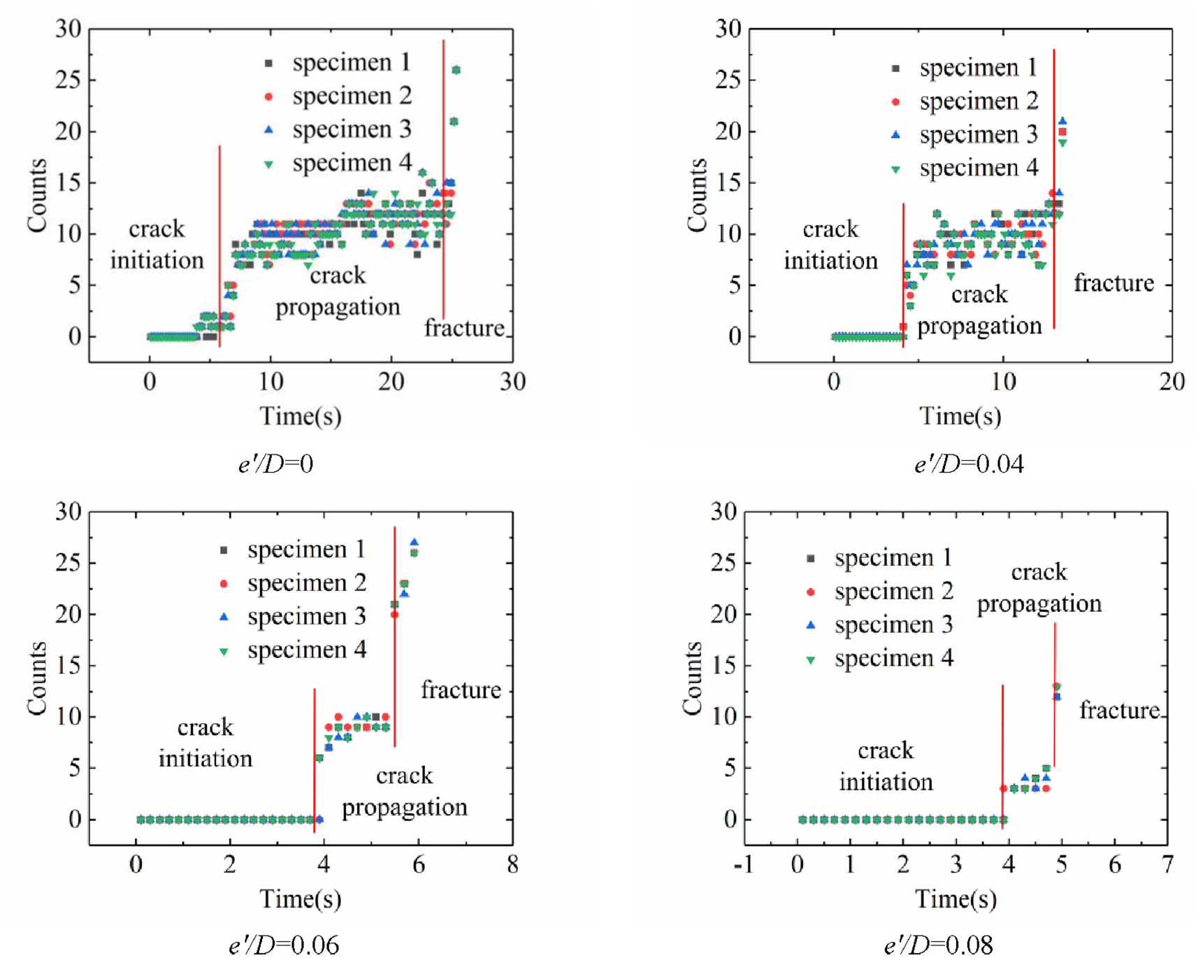
Cumulative counts with different eccentric ratio.
The phase characteristics of 16 Mn metal bar fracture
The threshold value of the peak amplitude is set as 0.2V. If the peak exceeds the threshold, an event occurred. In every 0.2 s, the number of events is called counts. As shown in Figure 5, the cropping process can be divided into three stages according to the AE counts. The first stage is the crack initiation stage, the second stage is the crack propagation stage and the third stage is the fracture stage.
In the crack initiation stage, the cumulative counts remain unchanged. The reasons for this phenomenon are as follows. In this stage, the metal bar is under the cyclic load, the irreversibility of the dislocation glide step leads to the development of surface roughness. As shown in Figure 6, with the increase in cycle index, micro-cracks form in persistent slip bands (PSBs) or slip-band extrusions. The plastic zone size is smaller than several grains diameter range, The crack growth rate is low and the average crack extension corresponding to each cycle is smaller than lattice spacing. All of this leads to a small accumulation of damage and small AE signal strength. As shown in Figure 4a, the voltage peak value of the AE signal from 3 s to 4 s is less than 0.15V. The amplitude of the signal was less than the peak amplitude threshold value (0.2V) and the peak amplitude accumulated count was equal to 0.
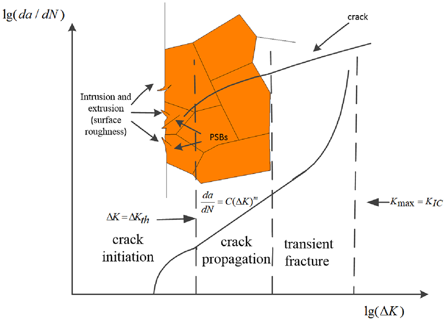
Schematic diagram of the fracture process.
As shown in Figure 5, in the crack propagation stage, the cumulative counts has a rapid ascent and the values of the signals are stable around a certain value. When the eccentric ratio increases from 0 to 0.08, the certain value decreases from 12 to 5. The above-mentioned phenomenons are relative to the characteristics of the crack propagation stage. In this stage, as shown in Figure 6, the size of the plastic zone at the crack tip reaches the level of multiple grain sizes. The range of the stress intensity factor is
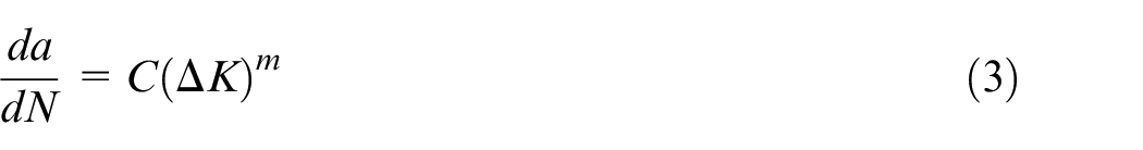
Where
As shown in Figure 5, in the fracture stage, the counts has a rapid increase. The phenomenon can be explained by the characteristics of the fracture stage. As shown in Figure 6, in this stage, the range of stress intensity factor
Where
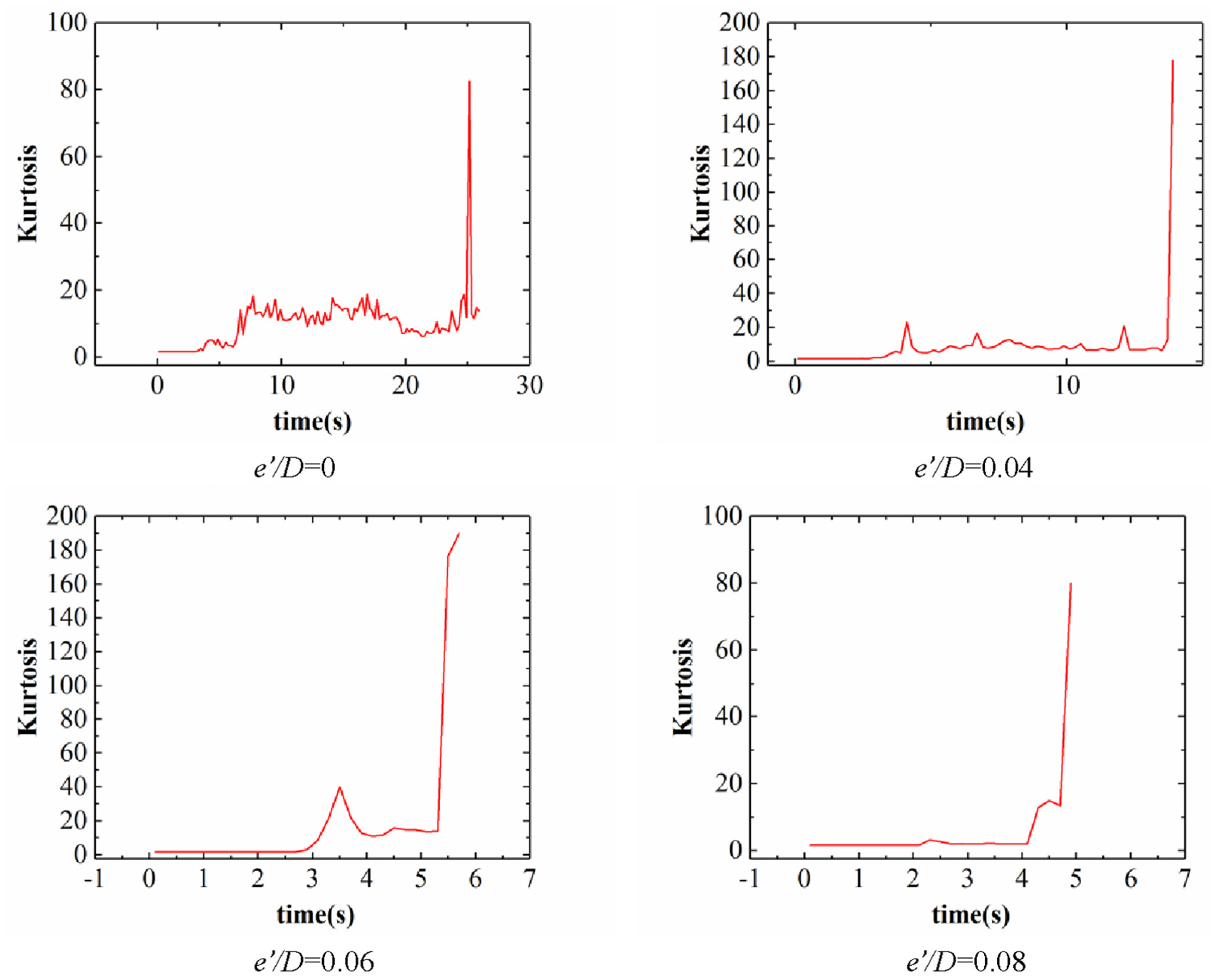
The kurtosis results of AE signal in different notch eccentricity situation.
The influence of notch eccentric ratio
The duration of the crack initiation stage, crack propagation stage and fracture stage with different eccentric ratio are presented in Figure 8. In the crack initiation stage, the average duration is about 2 s. The normalization of the average duration of the crack initiation stage with different eccentric ratios is shown in Figure 9. The value in this stage is equal to 0. The notch eccentric ratio has a little influence on the duration of the crack initiation stage. The reason for this phenomenon is that in the initiation stage
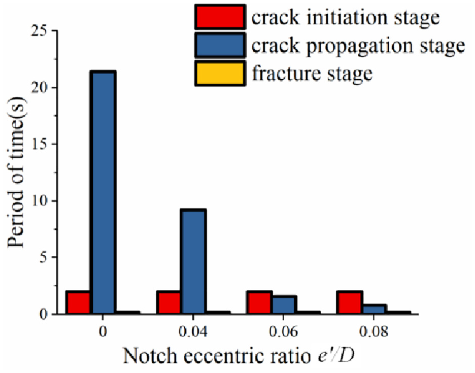
The duration of each stage with different notch eccentric ratio.
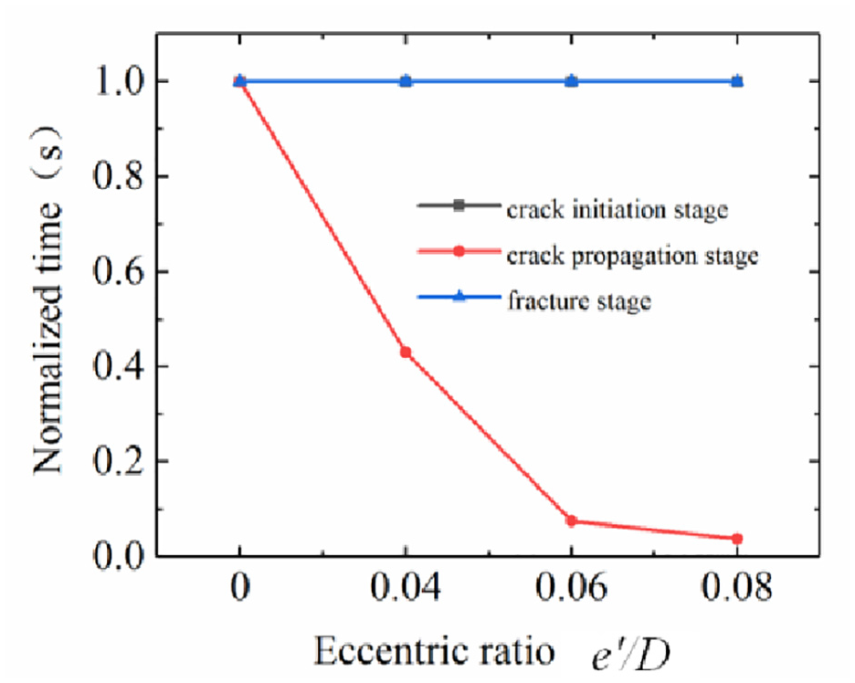
The normalized duration of each stage with different eccentric ratio.
In the crack propagation stage, when the notch eccentric ratio e’/D increases from 0 to 0.08, the average duration of the crack propagation decreased from 21.4 s to 0.8 s. The eccentric ratio has a great influence on the duration of the crack propagation stage and the average duration of the crack propagation stage decreases when the eccentric ratio increases. The normalization of the average duration of the crack propagation stage of each cropping process is shown in Figure 10. when the notch eccentric ratio e’/D increased from 0 to 0.04, the average duration of the crack propagation stage decreases by 0.57. When the notch eccentric ratio e’/D increases from 0.04 to 0.06, the average duration of the crack propagation stage decreases by 0.33. When the notch eccentric ratio e’/D increases from 0.06 to 0.08, the duration of the crack propagation stage decreased by 0.07. It was found that when the notch eccentricity increases, the decline rate of the duration became slower and slower. When the notch eccentricity e’/D increases from 0.06 to 0.08, the decline of the average duration is inconspicuous.
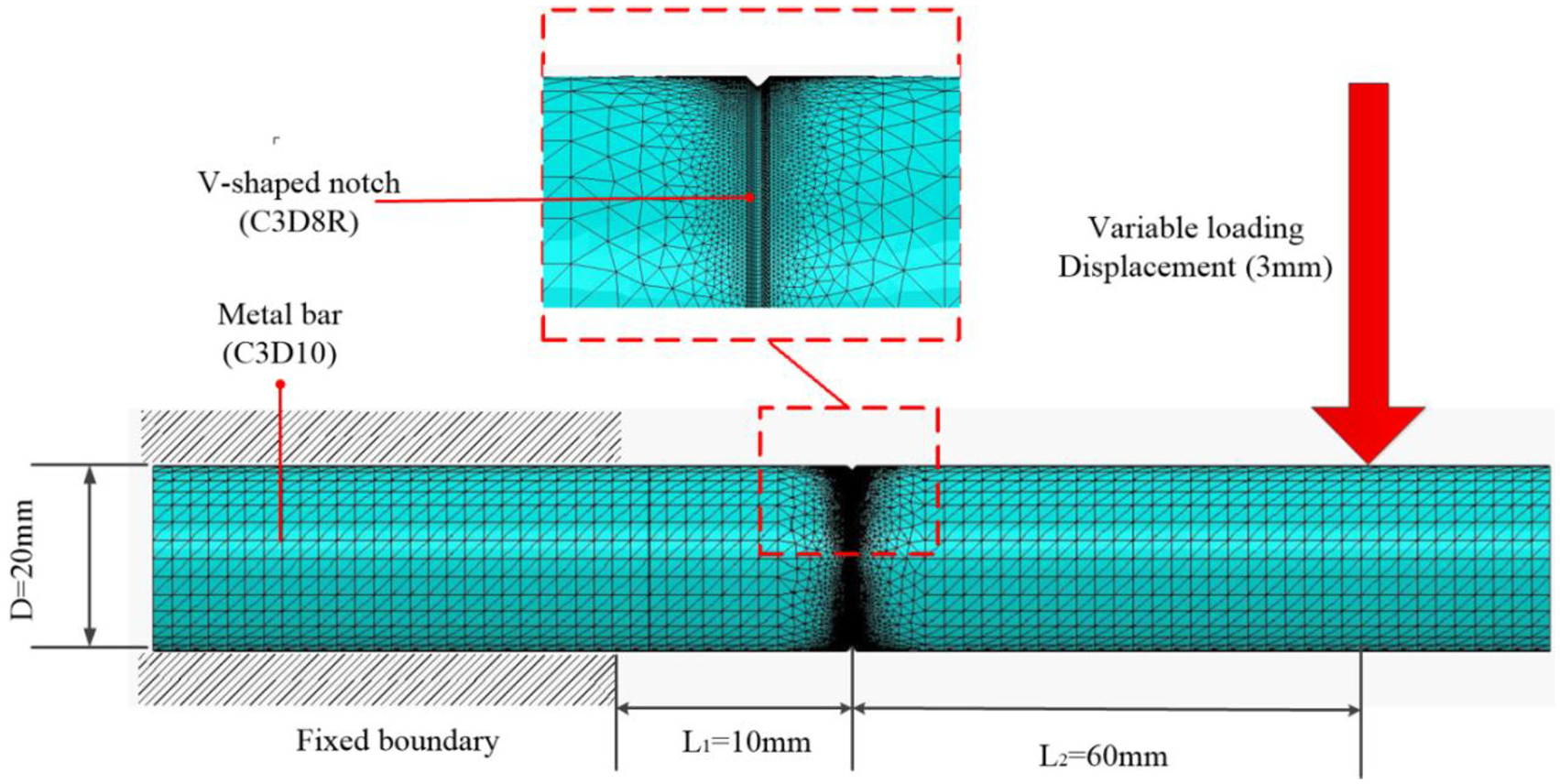
FEM model of 16 Mn metal bar(e’/D=0).
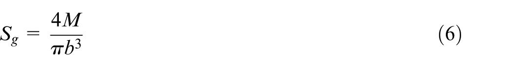
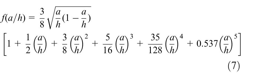
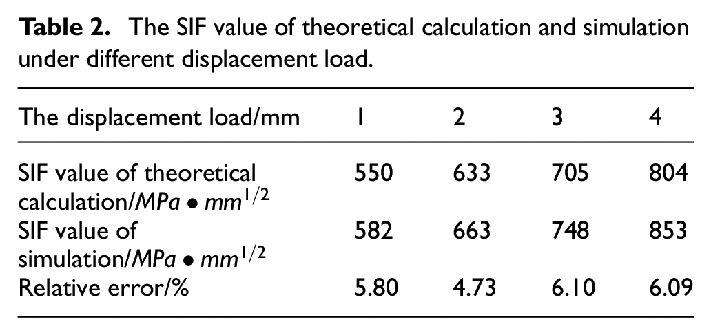
The above-mentioned phenomenon can be explained as follows: Due to the different eccentric ratios, the stress intensity factor around the crack tip changes. To calculate the SIFs around the crack tip, FEM models with different notch eccentric ratio were established. We applied the XFEM method with traction-separation cohesive damage criterion, to describe the cohesive zone ahead of the crack tip. The maximum principal stress damage is set as damage initiation criterion, and linear energy degradation as damage evolution rule based on fracture energy release rate. A FEM model (e’/D=0) is illustrated in Figure 10, which is established by Abaqus software. One end of the bar is fixed and the other end is subjected to a cyclic displacement load. The step of the analysis is direct cyclic. The crack is placed in the middle of notched zones. To obtain the SIFs, the crack is not allowed to grow. Besides, the number of contours was equal to 7. The metal bar is modeled with 8-node linear brick, reduced integration, hourglass control element (C3D8R element) at the notched zones, together with a 10-node quadratic tetrahedron element (C3D10 element). The number of elements is 471103. To ensure mesh convergence, the elements at notched zones are refined. The size of the element at notched zones is 0.1 mm. Besides, IA (maximum number of cutbacks allowed for an increment) is set as 20. The maximum SIF at the same position in this model. To confirm the validity of this model, the maximum SIF value (when displacement load = 1 mm, 2 mm, 3 mm, and 4 mm) of theoretical calculation and simulation are compared. The theoretical formula for computing SIFs is as follows. 32 The results were shown in Table 2. It can be seen the simulation results are reliable.

The SIF value of theoretical calculation and simulation under different displacement load.
As shown in Figure 11, when e’/D is equal to 0, 0.04, 0.06 or 0.08, the distribution of the SIFs around the circle of the crack tip are obtained by simulation. When e’/D=0, the maximum SIF is equal to 748MPa × mm1/2 at
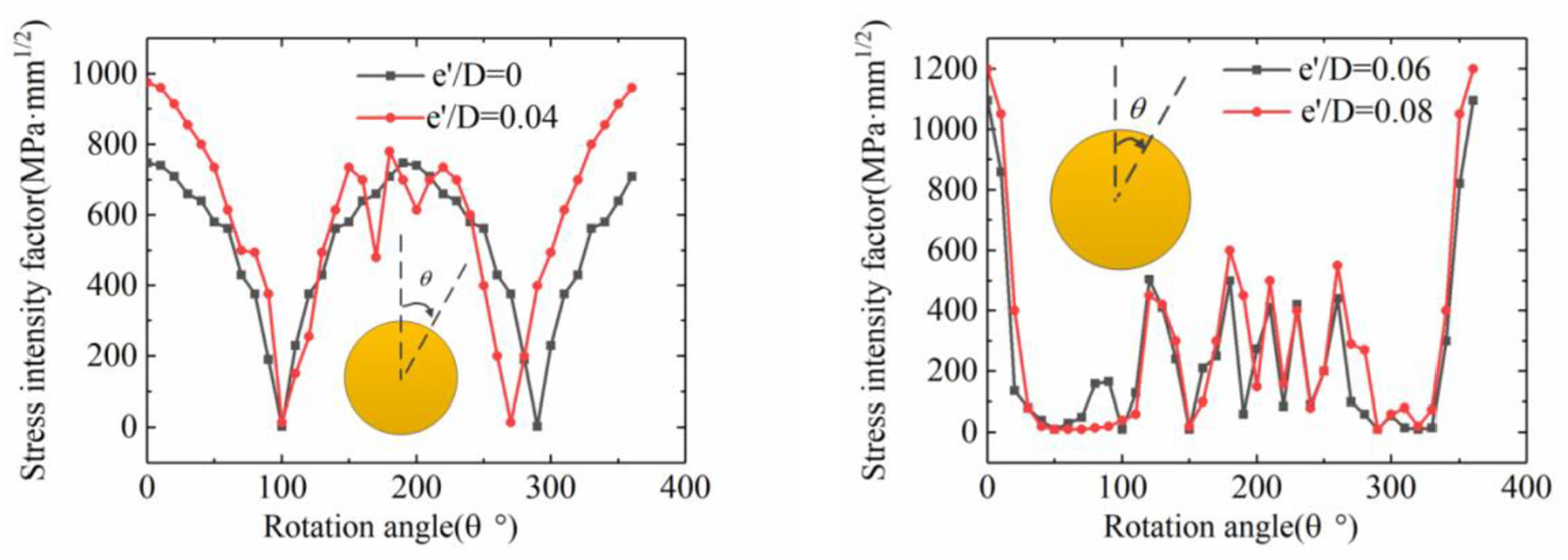
Distribution of the SIFs around the circle of the crack tip.
The range of the SIF has a great influence on the duration of the crack propagation stage.
In the fracture stage, as shown in Figure 8, the average duration of this stage is equal to 0.2 s. The phenomenon explained as follows: In this stage, the crack growth rate
The influence of notch eccentric ratio on the fracture section quality
The flatness degree of the cropping section represents the quality of the section.33,34 As shown in Figure 12, the prefabricated crack notch is removed (This method reduce the influence of the prefabricated crack notch. Section quality will be assessed better. In the industrial applications, the influence of the prefabricated crack notch can be reduced by using an advanced slotting method such as laser grooving.).The remaining area is the section quality evaluation area and h is the distance between the lowest section and the highest section. As shown in Figure 14, the cropping section of the metal bar with different eccentric ratio is obtained by the OLYMPUS DSX1000 with
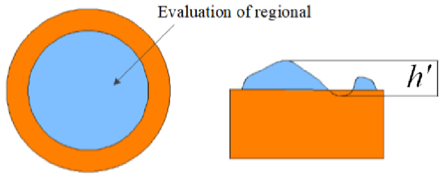
Section quality evaluation standard diagram.
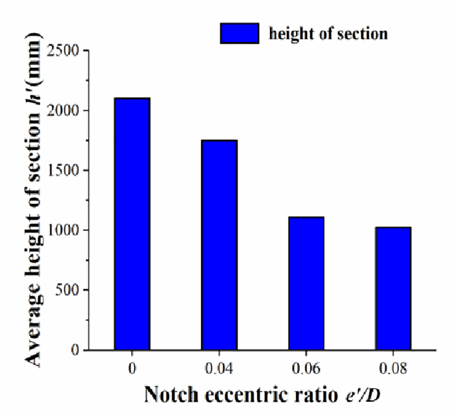
Average height of section with the different eccentric ratio.
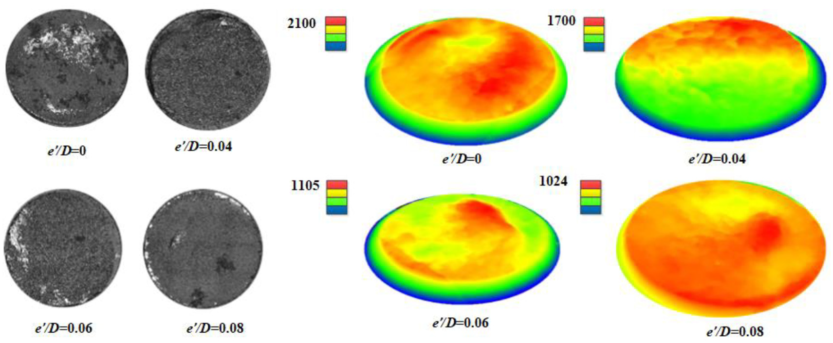
The photos of cropping section with different eccentric ratio and height information cloud map with the different eccentric ratio.
The results given above can be explained as follows: When the eccentric ratio of the metal bar increases, the unevenness of SIF around the notch root of the bars, occurs which accelerates the crack propagation and further leads to the decrease in the plastic deformation zone.
Combined with the influence of the eccentric ratio on the fracture section quality and time of the whole crack process, as shown in Figure 15, the increase of the eccentric ratio leads the fracture section quality improves and the time of the whole crack process reduces. When e’/D increases from 0.06 to 0.08, the trend is moderating.
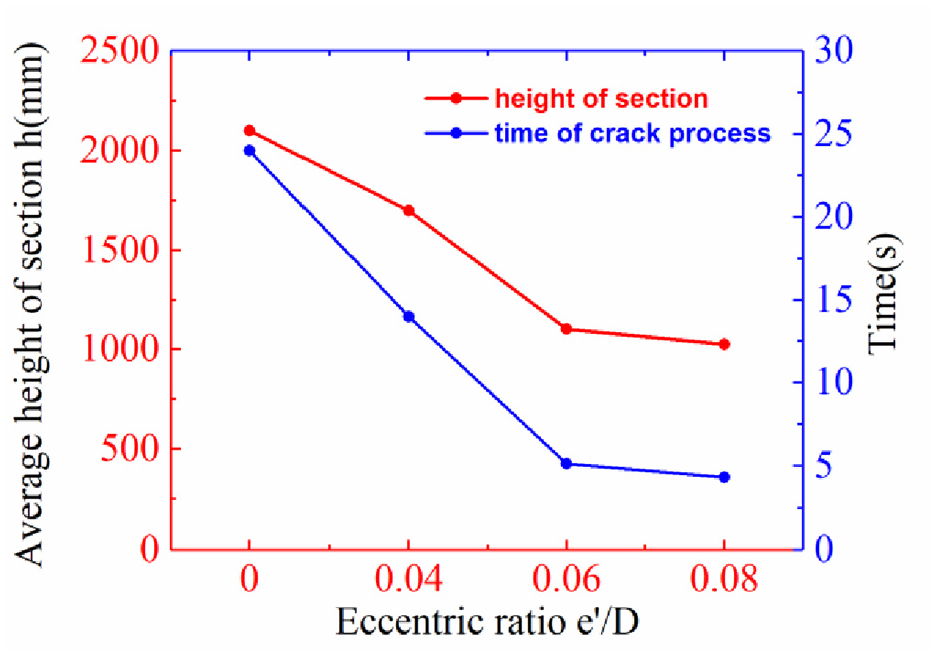
The red curve reflects the influence of the notch eccentric ratio on the fracture section quality, the blue curve reflects the influence of the notch eccentric ratio on the time of the whole crack process.
Conclusion
In this study, to investigate the AE parameter characteristics of the LCFC, a cropping system is established to carry out a series of LCFC experiments. The acoustic emission technology is used to obtain signals in the whole process. The AE parameters are used to describe the cropping process and the influence of the different notch eccentric ratio on the crack efficiency and fracture section quality. From the above results and discussions, the following conclusions can be drawn:
The process of LCFC with metal bars of 16 Mn steel is divided into three stages. The first stage is the crack initiation stage, the second stage is the crack propagation stage and the third stage is the fracture stage. The AE counts can be used to represent the status of the cropping process. The kurtosis can be used to represent the fracture stage of the cropping process.
In the crack initiation stage, the cumulative counts of the AE signal are equal to 0 and the notch eccentric ratio does not influence the duration of this period. Damage accumulation is too little to generate cracks in the notch of the metal bars. The duration of the crack initiation stage is almost unanimous, which is about 2 s. In the crack propagation stage, the cumulative counts of the AE signal have an increase compared with the crack initiation stage and the peak amplitude values accumulate counts of the AE signals stay stable around a certain value. In this stage, the notch eccentric ratio has a great influence on the duration of this period. When the eccentric ratio increases, the duration of this stage decreases; when the eccentric ratio increases, the decline rate of the duration becomes slower and slower. When the notch eccentric ratio increases from 0.06 to 0.08, the decline of the average duration is inconspicuous. In the fracture stage, the duration of this stage is extremely brief, the crack growth increases rapidly and the metal bar fractures abruptly.
The eccentric ratio of the notch has a great influence on the quality of the cropping section. With the increase of the eccentric ratio, the cropping section becomes flatter and flatter. An increase eccentric ratio improves the section quality and reduces the time of cropping. As the eccentric ratio increases, these effects recede. Combined with the influence of the eccentric ratio on the fracture section quality and time of the whole crack process, the results of the study will guide to improve low-stress fatigue cropping efficiency and section quality in industrial applications.
The AE monitoring technique is a useful method to detect the process of low-cycle fatigue cropping. It provide effective information to investigate the affection of the factors during the low-cycle fatigue process. The AE technique offer guidance to improve low-stress fatigue cropping efficiency and section quality in the LCFC method.
Footnotes
Appendix
Declaration of conflicting interests
The author(s) declared no potential conflicts of interest with respect to the research, authorship, and/or publication of this article.
Funding
The author(s) disclosed receipt of the following financial support for the research, authorship, and/or publication of this article: This work is supported by the National Natural Science Foundation of China for key Program (Grant No. 51335009), National Key Research and Development Program of China (Grant No. 2017YFD0700200), China Postdoctoral Science Foundation (Grant No. 2018M643627) and the National Natural Science Foundation of PR China (Approval No. 51575532).
Availability of data and material
We declare that materials described in the manuscript, including all relevant raw data, will be freely available to any scientist wishing to use them for non-commercial purposes, without breaching participant confidentiality.